EP0480840B1 - Verfahren und Vorrichtung zur Abtrennung durch Adsorption von mindestens einem Bestandteil einer Gasmischung - Google Patents
Verfahren und Vorrichtung zur Abtrennung durch Adsorption von mindestens einem Bestandteil einer Gasmischung Download PDFInfo
- Publication number
- EP0480840B1 EP0480840B1 EP91402714A EP91402714A EP0480840B1 EP 0480840 B1 EP0480840 B1 EP 0480840B1 EP 91402714 A EP91402714 A EP 91402714A EP 91402714 A EP91402714 A EP 91402714A EP 0480840 B1 EP0480840 B1 EP 0480840B1
- Authority
- EP
- European Patent Office
- Prior art keywords
- adsorption
- adsorbent
- perforations
- cycle
- masses
- Prior art date
- Legal status (The legal status is an assumption and is not a legal conclusion. Google has not performed a legal analysis and makes no representation as to the accuracy of the status listed.)
- Expired - Lifetime
Links
- 238000001179 sorption measurement Methods 0.000 title claims abstract description 35
- 238000000034 method Methods 0.000 title claims abstract description 20
- 239000000470 constituent Substances 0.000 title claims abstract description 7
- 239000000203 mixture Substances 0.000 title description 10
- 239000003463 adsorbent Substances 0.000 claims abstract description 39
- 239000007789 gas Substances 0.000 claims abstract description 27
- 238000004519 manufacturing process Methods 0.000 claims abstract description 27
- QVGXLLKOCUKJST-UHFFFAOYSA-N atomic oxygen Chemical compound [O] QVGXLLKOCUKJST-UHFFFAOYSA-N 0.000 claims abstract description 12
- 239000001301 oxygen Substances 0.000 claims abstract description 12
- 229910052760 oxygen Inorganic materials 0.000 claims abstract description 12
- 239000008246 gaseous mixture Substances 0.000 claims abstract description 8
- 125000004122 cyclic group Chemical group 0.000 claims abstract description 3
- IJGRMHOSHXDMSA-UHFFFAOYSA-N Atomic nitrogen Chemical compound N#N IJGRMHOSHXDMSA-UHFFFAOYSA-N 0.000 claims description 4
- 239000002245 particle Substances 0.000 claims description 4
- 238000003795 desorption Methods 0.000 claims description 2
- 229910052757 nitrogen Inorganic materials 0.000 claims description 2
- 238000000926 separation method Methods 0.000 description 13
- 238000010926 purge Methods 0.000 description 10
- 238000009434 installation Methods 0.000 description 8
- 238000009826 distribution Methods 0.000 description 5
- 238000010828 elution Methods 0.000 description 5
- 230000000750 progressive effect Effects 0.000 description 4
- 238000004891 communication Methods 0.000 description 3
- 230000007704 transition Effects 0.000 description 3
- CURLTUGMZLYLDI-UHFFFAOYSA-N Carbon dioxide Chemical compound O=C=O CURLTUGMZLYLDI-UHFFFAOYSA-N 0.000 description 2
- CBENFWSGALASAD-UHFFFAOYSA-N Ozone Chemical compound [O-][O+]=O CBENFWSGALASAD-UHFFFAOYSA-N 0.000 description 2
- 240000008042 Zea mays Species 0.000 description 2
- 230000033228 biological regulation Effects 0.000 description 2
- 238000005516 engineering process Methods 0.000 description 2
- 238000009776 industrial production Methods 0.000 description 2
- 238000012423 maintenance Methods 0.000 description 2
- 239000000463 material Substances 0.000 description 2
- 238000012360 testing method Methods 0.000 description 2
- 239000002699 waste material Substances 0.000 description 2
- 241000196324 Embryophyta Species 0.000 description 1
- 241000897276 Termes Species 0.000 description 1
- OGIIWTRTOXDWEH-UHFFFAOYSA-N [O].[O-][O+]=O Chemical compound [O].[O-][O+]=O OGIIWTRTOXDWEH-UHFFFAOYSA-N 0.000 description 1
- PNEYBMLMFCGWSK-UHFFFAOYSA-N aluminium oxide Inorganic materials [O-2].[O-2].[O-2].[Al+3].[Al+3] PNEYBMLMFCGWSK-UHFFFAOYSA-N 0.000 description 1
- 239000001569 carbon dioxide Substances 0.000 description 1
- 229910002092 carbon dioxide Inorganic materials 0.000 description 1
- 238000010276 construction Methods 0.000 description 1
- 238000007796 conventional method Methods 0.000 description 1
- 238000011161 development Methods 0.000 description 1
- 238000005265 energy consumption Methods 0.000 description 1
- 239000010419 fine particle Substances 0.000 description 1
- 239000001257 hydrogen Substances 0.000 description 1
- 229910052739 hydrogen Inorganic materials 0.000 description 1
- 125000004435 hydrogen atom Chemical class [H]* 0.000 description 1
- 238000005086 pumping Methods 0.000 description 1
- 230000001105 regulatory effect Effects 0.000 description 1
- 230000000717 retained effect Effects 0.000 description 1
- 238000007789 sealing Methods 0.000 description 1
- 239000007787 solid Substances 0.000 description 1
- 238000012549 training Methods 0.000 description 1
- 230000001052 transient effect Effects 0.000 description 1
- 239000002912 waste gas Substances 0.000 description 1
Images

Classifications
-
- B—PERFORMING OPERATIONS; TRANSPORTING
- B01—PHYSICAL OR CHEMICAL PROCESSES OR APPARATUS IN GENERAL
- B01D—SEPARATION
- B01D53/00—Separation of gases or vapours; Recovering vapours of volatile solvents from gases; Chemical or biological purification of waste gases, e.g. engine exhaust gases, smoke, fumes, flue gases, aerosols
- B01D53/02—Separation of gases or vapours; Recovering vapours of volatile solvents from gases; Chemical or biological purification of waste gases, e.g. engine exhaust gases, smoke, fumes, flue gases, aerosols by adsorption, e.g. preparative gas chromatography
- B01D53/06—Separation of gases or vapours; Recovering vapours of volatile solvents from gases; Chemical or biological purification of waste gases, e.g. engine exhaust gases, smoke, fumes, flue gases, aerosols by adsorption, e.g. preparative gas chromatography with moving adsorbents, e.g. rotating beds
-
- B—PERFORMING OPERATIONS; TRANSPORTING
- B01—PHYSICAL OR CHEMICAL PROCESSES OR APPARATUS IN GENERAL
- B01D—SEPARATION
- B01D2253/00—Adsorbents used in seperation treatment of gases and vapours
- B01D2253/10—Inorganic adsorbents
- B01D2253/104—Alumina
-
- B—PERFORMING OPERATIONS; TRANSPORTING
- B01—PHYSICAL OR CHEMICAL PROCESSES OR APPARATUS IN GENERAL
- B01D—SEPARATION
- B01D2256/00—Main component in the product gas stream after treatment
- B01D2256/10—Nitrogen
-
- B—PERFORMING OPERATIONS; TRANSPORTING
- B01—PHYSICAL OR CHEMICAL PROCESSES OR APPARATUS IN GENERAL
- B01D—SEPARATION
- B01D2256/00—Main component in the product gas stream after treatment
- B01D2256/12—Oxygen
-
- B—PERFORMING OPERATIONS; TRANSPORTING
- B01—PHYSICAL OR CHEMICAL PROCESSES OR APPARATUS IN GENERAL
- B01D—SEPARATION
- B01D2256/00—Main component in the product gas stream after treatment
- B01D2256/14—Ozone
-
- B—PERFORMING OPERATIONS; TRANSPORTING
- B01—PHYSICAL OR CHEMICAL PROCESSES OR APPARATUS IN GENERAL
- B01D—SEPARATION
- B01D2257/00—Components to be removed
- B01D2257/10—Single element gases other than halogens
- B01D2257/106—Ozone
-
- B—PERFORMING OPERATIONS; TRANSPORTING
- B01—PHYSICAL OR CHEMICAL PROCESSES OR APPARATUS IN GENERAL
- B01D—SEPARATION
- B01D2259/00—Type of treatment
- B01D2259/40—Further details for adsorption processes and devices
- B01D2259/40011—Methods relating to the process cycle in pressure or temperature swing adsorption
- B01D2259/40043—Purging
- B01D2259/4005—Nature of purge gas
- B01D2259/40052—Recycled product or process gas
-
- B—PERFORMING OPERATIONS; TRANSPORTING
- B01—PHYSICAL OR CHEMICAL PROCESSES OR APPARATUS IN GENERAL
- B01D—SEPARATION
- B01D53/00—Separation of gases or vapours; Recovering vapours of volatile solvents from gases; Chemical or biological purification of waste gases, e.g. engine exhaust gases, smoke, fumes, flue gases, aerosols
- B01D53/02—Separation of gases or vapours; Recovering vapours of volatile solvents from gases; Chemical or biological purification of waste gases, e.g. engine exhaust gases, smoke, fumes, flue gases, aerosols by adsorption, e.g. preparative gas chromatography
- B01D53/04—Separation of gases or vapours; Recovering vapours of volatile solvents from gases; Chemical or biological purification of waste gases, e.g. engine exhaust gases, smoke, fumes, flue gases, aerosols by adsorption, e.g. preparative gas chromatography with stationary adsorbents
- B01D53/0407—Constructional details of adsorbing systems
- B01D53/0431—Beds with radial gas flow
-
- B—PERFORMING OPERATIONS; TRANSPORTING
- B01—PHYSICAL OR CHEMICAL PROCESSES OR APPARATUS IN GENERAL
- B01D—SEPARATION
- B01D53/00—Separation of gases or vapours; Recovering vapours of volatile solvents from gases; Chemical or biological purification of waste gases, e.g. engine exhaust gases, smoke, fumes, flue gases, aerosols
- B01D53/02—Separation of gases or vapours; Recovering vapours of volatile solvents from gases; Chemical or biological purification of waste gases, e.g. engine exhaust gases, smoke, fumes, flue gases, aerosols by adsorption, e.g. preparative gas chromatography
- B01D53/04—Separation of gases or vapours; Recovering vapours of volatile solvents from gases; Chemical or biological purification of waste gases, e.g. engine exhaust gases, smoke, fumes, flue gases, aerosols by adsorption, e.g. preparative gas chromatography with stationary adsorbents
- B01D53/047—Pressure swing adsorption
Definitions
- the present invention relates to methods of separation by adsorption of at least one constituent of a gas mixture, of the kind where said gas mixture circulates in a mass of adsorbent of a plurality of masses adsorbent during an adsorption cycle comprising at least one phase adsorption up to high cycle pressure and a desorption phase up to a low cycle pressure, the high cycle pressure being at least double the low cycle pressure.
- the various adsorbent masses are placed in a plurality of cans, with or without auxiliary capacity according to the pressure cycle.
- PSA pressure variation processes
- An industrial production therefore implements at least two adsorbers and generally three adsorbers to operate the as continuous as possible rotating machines (compressor, vacuum pump the if applicable) with piping, valves, some of which must be regulated, and an automaton to carry out the cycle.
- rotating machines compressor, vacuum pump the if applicable
- piping, valves some of which must be regulated, and an automaton to carry out the cycle.
- automaton to carry out the cycle.
- the investment of such units is expensive, in particular because of the cost of the adsorbent material which large quantities are required.
- Document US-A-1,590,266 describes a device with compartments sector adsorbents arranged to rotate around a vertical axis for placing work of a separation process by adsorption with temperature variation, says TSA, with very long cycle time and slow rotation speed.
- the objective of the present invention is to combine the advantages of solutions proposed in adsorption with pressure variation by removing their disadvantages, namely high productivity with high performance and low investment while offering reliable industrial production.
- the invention also relates to a device for separation by adsorption at cyclic pressure variation of at least one gaseous component of a mixture gaseous, comprising a plurality of adsorption units each comprising a mass of adsorbent, and sequential means of feeding and gaseous withdrawal of the various adsorption units, to carry out a cycle adsorption, characterized in that the adsorption units are made up each sector-shaped and arranged in an envelope structure tubular delimiting, for each adsorption unit, a longitudinal collector interior and an exterior longitudinal manifold connected to a radial manifold end, the tubular casing structure being rotatably mounted around of an axis on a stationary support having an outer surface coaxial with the axis and cooperating in substantially sealed contact with an interior surface of the envelope structure, the stationary support defining a first and a second set of axially offset chambers respectively provided with a first and second series of angularly distributed passages opening into the outer surface and cooperating selectively with a
- the invention thus makes it possible to simply carry out all kinds of cycles separation from the simplest to the most sophisticated.
- the different rooms are grouped into one cylindrical distributor box arranged inside the shaft-bearing-support of the sectoral adsorbent compartments.
- the cycle thus carried out can be made very complex and therefore extremely efficient, it depends on the number of compartments created: adsorption zone, balancing zone, purge zone, elution zone, recompression zone, etc ...
- Such complex cycles could not be made according to the known technique only with a large number of canisters, which increases the cost of investment (number of valves, of pipes) and increases the size.
- the radial thickness of the adsorbent that the gas crosses in the direction horizontal is minimal. Tests have shown that to ensure good separation of the gas mixture, this radial thickness of adsorbent must not fall below 30 cm with current adsorbents, in the case of oxygen production.
- the process of the invention is perfectly continuous, without valve, without piping, without automaton, without regulation.
- this type of adsorber can be produced in a standardized module: for example 10 t / d of oxygen (i.e. less than 3 m 3 of adsorbent for a diameter of 2 m and a height of 2 m) and the units industrial plants are composed of machines (compressors, vacuum pump if necessary) and the number of adsorption modules required for the total capacity (eg 5 rotary adsorbers for 50 T / d).
- This modular construction allows continuous maintenance of the material (shutdown of only one of the adsorbers) and flexibility of adjustment of the flow rate to be produced from 0 to 100%, in particular by adjusting the rotational speed, a purity setting of 22 to 95%, which are currently almost impossible on a traditional unit of the type canisters and valves, where the simple replacement of a valve requires total shutdown of the installation, while obtaining flexibility of flow leads to providing for very complex regulation.
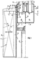
- an installation according to the invention comprises an adsorption unit 1 mounted on a rotary support shaft 2, typically vertical, and a distribution assembly stationary gas 3.
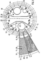
- the adsorption unit 1 consists of a plurality of sectoral compartments 11 arranged around the shaft 2 having a longitudinal extension in the height direction over almost the entire bearing of the support shaft 2 and having in a horizontal plane a contour in the shape of a trapezoidal sector, with small bases 12 and large bases 13 inscribed in circles concentric with the axis of the support shaft 2 and radial side walls 14 and 15, the whole forming a crown of identical compartments 11 mounted integral of the support shaft 2.
- the sector compartments 11 are filled with adsorbent 16.
- the small bases 12 and large bases 13 are produced in the form of perforated panels or grids, so as to form passage windows gas, while the solid side walls 14 and 15 extend radially towards the support shaft 2 and radially outwards beyond bases 12 and 13, so as to form, for each compartment sector 11, a first gas collector 18 with the external wall of the support shaft 2, radially inner side, and a second collector 19 with an outer wall 20, on the radially outer side.
- the angular extension of a compartment 11 is 15 °, so that has 24 sectoral compartments 11 all around the support shaft 2.
- the support shaft 2 is a hollow shaft which is fixed on a bearing internal itself hollow 22, mounted for rotation at the end of a vertical pivot 23.
- the continuous rotational movement of the support shaft 2 around the pivot 23 is provided by electric motor and gears, so described.
- the gas distribution assembly 3 is formed of a box fixed cylindrical 31 mounted with sealed sliding inside the hollow bearing 22, the upper end of the bearing 22 and of the support shaft 2 protruding above the upper end wall 24 of the sectoral compartments 11.
- the side walls 14, 15 of the various compartments sectoral 11 also extend upwards, as well as a wall outer 20 to form with a substantially annular wall radial 25 as many substantially radial conduits 26 as there are sectoral compartments 11, each communicating with a collector 19 associated with a sectoral compartment 11.
- the interior collectors 18 communicate with the box 31 by aligned perforations 32 of shaft 2 and 33 of bearing 22, each in number equal to that of the number of sectoral compartments 11 (24 at drawing).
- the external collectors 19 communicate with the box 31, via the radial conduits 26, by a second series of aligned perforations 34 of shaft 2 and 35 of bearing 22, also in number equal to that of the number of sectoral compartments 11.
- the box 31 has, through its side wall cylindrical 36 a double series of perforations 37, 38 of which the gap angle is the same, or a multiple, of the angular deviation of perforations (32-33) and (34-35), and located on the same levels respective.
- the cylindrical box 31 is itself subdivided into several chambers, on the one hand by a transverse wall (horizontal) 41 extending at an intermediate level between the perforations (32-33-37) on the one hand and (34-35-38), on the other hand and, below the wall horizontal 41, by a vertical middle wall 42. It is understood that at during the simultaneous rotation of the support shaft 2 and of the bearing 22, the perforations 37 of the two recesses 43 and 44 defined by the walls 41 and 42 are presented successively with respect to the different simultaneously movable perforations in rotation 32 and 33.
- the recess 43 is connected by a pipe 45 to a source of gaseous mixture at treat, while the recess 44 is connected by a tube 46 for waste gases to be evacuated.
- the upper part of the box 31, at the perforations mobile 34 and 35 and box perforations 38 is itself subdivided into three recesses 47, 48, 49 by two walls 50 and 51 extending longitudinally on either side of an axial median plane.
- the recess 47 above the recess 43 is connected to the outside by a production gas discharge pipe 52, while the chamber 48 is connected by a tube 53 to a reserve of production gas, while the chamber 49 is a balancing chamber formed without communication to the outside other than the high perforations 38.
- the methods and equipment according to the invention can be performed differently from what has just been described.
- the different perforations on the mobile unit can be made under form of a plurality of longitudinal slots.
- the different passages affecting a room data can be made in the form of an annular slot.
- the dispenser can be designed to provide external radial inlet of the mixture to be treated and a racking radially intense from the production gas.
- the distribution assembly (fixed distributor and mobile unit) can also, for improved sealing and centering, have a general conical configuration.
- the invention applies to the separation of air for production oxygen, nitrogen and also to the production of hydrogen, carbon dioxide and many other gases from mixtures containing them.
Landscapes
- Chemical & Material Sciences (AREA)
- Engineering & Computer Science (AREA)
- Analytical Chemistry (AREA)
- General Chemical & Material Sciences (AREA)
- Oil, Petroleum & Natural Gas (AREA)
- Chemical Kinetics & Catalysis (AREA)
- Separation Of Gases By Adsorption (AREA)
- Separation Using Semi-Permeable Membranes (AREA)
Claims (9)
- Verfahren zur Abtrennung mindestens eines gasförmigen Bestandteils von einem gasförmigen Gemisch mittels Adsorption, bei dem das gasförmige Gemisch während eines Adsorptionszyklus in eine von zahlreichen Adsorbtionsmittelmassen strömt, wobei der Zyklus mindestens eine Adsorptionsphase bis zu einem Zyklushochdruck und eine Desorptionsphase bis zu einem Zyklusniederdruck umfaßt und der Zyklushochdruck mindestens doppelt so hoch wie der Zyklusniederdruck ist, dadurch gekennzeichnet, daß ein Adsorptionsmittel mit einer Korngröße kleiner 1,7 mm in einer Vielzahl von sektoriellen Massen rings um eine Achse angeordnet wird, wobei die Zahl der Massen größer ist als die Anzahl der unterschiedlichen Phasen eines Adsorptionszyklus, die je Umdrehung durchlaufen werden, daß in dem Adsorber ein radialer, zentripetaler oder zentrifugaler Gasfluß in Richtung auf längsgestreckte Kollektoren, von denen einer (18) radial innenseitig, der andere (19) radial außenseitig von den sektoriellen Adsorptionsmittelmassen angeordnet ist, erzeugt wird, und daß den sektoriellen Massen eine gleichbleibende Drehgeschwindigkeit erteilt wird, die zwischen ungefähr 2 und 20 U/min liegt.
- Verfahren nach Anspruch 1, dadurch gekennzeichnet, daß die Darstellungsparameter für den gasförmigen Bestandteil durch Einstellen der Drehzahl eingestellt werden.
- Verfahren nach einem der Ansprüche 1 oder 2, dadurch gekennzeichnet, daß der Zyklus mindestens eine Phase zur Einstellung des Gleichgewichts zwischen einer unter dem Zyklushochdruck stehenden sektoriellen Masse und einer unter dem Zyklusniederdruck stehenden sektoriellen Masse umfaßt.
- Verfahren nach einem der vorstehenden Ansprüche, dadurch gekennzeichnet, daß der Zyklus eine Phase des abschließenden, erneuten Unterdrucksetzens bis auf den Zyklushochdruck mittels des abgeschiedenen, gasförmigen Bestandteils des gasförmigen Gemisches umfaßt.
- Verfahren nach einem der vorstehenden Ansprüche, dadurch gekennzeichnet, daß das gasförmige Gemisch im wesentlichen aus Stickstoff und Sauerstoff besteht.
- Verfahren nach Anspruch 2 und Anspruch 5, dadurch gekennzeichnet, daß die Drehzahl auf das Herstellen von Sauerstoff mit einer Reinheit zwischen 22 % und 95 % eingestellt wird.
- Vorrichtung zur Abtrennung mindestens eines gasförmigen Bestandteils aus einem gasförmigen Gemisch mittels Adsorption bei zyklischer Druckänderung, umfassend eine Vielzahl von Adsorptionseinheiten, die jeweils eine Adsorptionsmittelmasse enthalten, und Mittel zur aufeinanderfolgenden Speisung und zur Entnahme von Gas aus verschiedenen Adsorptionseinheiten, um einen Adsorptionszyklus zu durchlaufen, dadurch gekennzeichnet, daß die Adsorptionseinheiten jeweils als Kreissektoren (11) ausgebildet und in einer rohrförmigen Gehäusekonstruktion (2, 20) angeordnet sind, die je Adsorptionseinheit einen inneren, längsgestreckten Kollektor (18) und einen äußeren, längsgestreckten Kollektor (19), der mit einem radial angeordneten Endkollektor (26) verbunden ist, begrenzt, wobei die rohrförmige Gehäusekonstruktion um eine Achse drehbar auf einem stationären Träger (3) mit einer koaxial zu der Achse angeordneten Außenfläche (36) angeordnet ist, der im wesentlichen dichtend mit einer Innenfläche (22) der Gehäusekonstruktion zusammenwirkt und der stationäre Träger (3) eine erste (4, 34) und eine zweite (47, 48, 49) Gruppe von Kammern hat, die axial versetzt sind und jeweils mit einer ersten (37) und einer zweiten (38) Reihe von rings um die Achse verteilten Kanälen versehen sind, die in die Außenfläche münden und selektiv mit einer ersten (32, 33) und einer zweiten (34, 35) Reihe von rings um die Achse verteilten Öffnungen zusammenwirken, die in die Innenfläche der rohrförmigen Gehäusekonstruktion münden und mit den inneren, längsgestreckten Kollektoren (18) bzw. den radial angeordneten Endkollektoren (26) der Adsorptionseinheiten (11) verbunden sind, daß die Anzahl der Kreissektoren (11) großer als die Zahl unterschiedlicher Phasen des Adsorptionszyklusses je Umlauf ist, daß sie Mittel zur gleichförmigen Drehung der rohrfömigen Gehäusekonstruktion mit einer Drehzahl zwischen ungefähr 2 und 20 U/min umfaßt, und daß das Adsorptionsmittel eine Korngröße kleiner 1,7 mm hat.
- Vorrichtung nach Anspruch 7, dadurch gekennzeichnet, daß die radiale Dicke des Adsorptionsmittels jeder Adsorptionseinheit (11) nicht kleiner als 30 cm ist.
- Verwendung einer Vorrichtung nach einem der Ansprüche 7 und 8 zur Herstellung von Sauerstoff aus Luft.
Applications Claiming Priority (2)
| Application Number | Priority Date | Filing Date | Title |
|---|---|---|---|
| FR9012538A FR2667801B1 (fr) | 1990-10-11 | 1990-10-11 | Procede et equipement de separation par adsorption d'au moins un constituant d'un melange gazeux. |
| FR9012538 | 1990-10-11 |
Publications (2)
| Publication Number | Publication Date |
|---|---|
| EP0480840A1 EP0480840A1 (de) | 1992-04-15 |
| EP0480840B1 true EP0480840B1 (de) | 1998-04-22 |
Family
ID=9401119
Family Applications (1)
| Application Number | Title | Priority Date | Filing Date |
|---|---|---|---|
| EP91402714A Expired - Lifetime EP0480840B1 (de) | 1990-10-11 | 1991-10-11 | Verfahren und Vorrichtung zur Abtrennung durch Adsorption von mindestens einem Bestandteil einer Gasmischung |
Country Status (10)
| Country | Link |
|---|---|
| US (1) | US5133784A (de) |
| EP (1) | EP0480840B1 (de) |
| JP (1) | JPH05137938A (de) |
| AT (1) | ATE165249T1 (de) |
| AU (1) | AU636095B2 (de) |
| BR (1) | BR9104403A (de) |
| CA (1) | CA2053213A1 (de) |
| DE (1) | DE69129288T2 (de) |
| ES (1) | ES2118078T3 (de) |
| FR (1) | FR2667801B1 (de) |
Families Citing this family (58)
| Publication number | Priority date | Publication date | Assignee | Title |
|---|---|---|---|---|
| EP0512534B1 (de) * | 1991-05-09 | 1996-09-04 | Mitsubishi Jukogyo Kabushiki Kaisha | Vorrichtung zur Trennung und Zurückgewinnung von Gasen |
| US5222980A (en) * | 1991-09-27 | 1993-06-29 | Medtronic, Inc. | Implantable heart-assist device |
| FR2689785B1 (fr) | 1992-04-13 | 1994-05-20 | Air Liquide | Dispositif rotatif de separation par adsorption d'au moins un constituant d'un melange gazeux. |
| LU88160A1 (fr) * | 1992-08-18 | 1993-10-27 | Fernande Schartz | Procede et dispositif de separation de gaz par adsorption selective a pression variable |
| US5487775A (en) * | 1994-05-09 | 1996-01-30 | The Boc Group, Inc. | Continuous pressure difference driven adsorption process |
| FR2722426B1 (fr) * | 1994-07-18 | 1996-08-23 | Air Liquide | Procede de separation d'azote d'un melange gazeux par adsorption |
| US5628819A (en) * | 1995-09-28 | 1997-05-13 | Calgon Carbon Corporation | Method and apparatus for continuous adsorption of adsorbable contaminates and adsorber regeneration |
| US5779771A (en) * | 1995-11-07 | 1998-07-14 | Calgon Carbon Corporation | Rotating flow distributor assembly for use in continuously distributing decontamination and regeneration fluid flow |
| US5681376A (en) * | 1995-11-07 | 1997-10-28 | Calgon Carbon Corporation | Rotating flow distributor assembly for use in continuously distributing decontamination and regeneration fluid flow |
| SE517561C2 (sv) * | 1996-03-04 | 2002-06-18 | Aga Ab | Förfarande och anordning för framställning av en gas genom separation från en gasblandning |
| US6063161A (en) | 1996-04-24 | 2000-05-16 | Sofinoy Societte Financiere D'innovation Inc. | Flow regulated pressure swing adsorption system |
| USRE38493E1 (en) * | 1996-04-24 | 2004-04-13 | Questair Technologies Inc. | Flow regulated pressure swing adsorption system |
| US5759242A (en) * | 1996-07-23 | 1998-06-02 | Praxair Technology, Inc. | Radial bed vaccum/pressure swing adsorber vessel |
| US6056804A (en) * | 1997-06-30 | 2000-05-02 | Questor Industries Inc. | High frequency rotary pressure swing adsorption apparatus |
| AU752114B2 (en) * | 1997-12-01 | 2002-09-05 | Air Products And Chemicals, Inc. | Modular pressure swing adsorption apparatus |
| US7094275B2 (en) * | 1997-12-01 | 2006-08-22 | Questair Technologies, Inc. | Modular pressure swing adsorption apparatus |
| US6051050A (en) * | 1997-12-22 | 2000-04-18 | Questor Industries Inc. | Modular pressure swing adsorption with energy recovery |
| US6921597B2 (en) * | 1998-09-14 | 2005-07-26 | Questair Technologies Inc. | Electrical current generation system |
| JP2000117039A (ja) * | 1998-10-15 | 2000-04-25 | Toshiba Corp | 気体分離装置 |
| US6086659A (en) * | 1999-01-29 | 2000-07-11 | Air Products And Chemicals, Inc. | Radial flow adsorption vessel |
| AU5466400A (en) | 1999-06-04 | 2000-12-28 | Flair Corporation | Rotating drum adsorber process and system |
| WO2000076628A1 (en) | 1999-06-09 | 2000-12-21 | Questair Technologies Inc. | Rotary pressure swing adsorption apparatus |
| WO2000076629A1 (en) * | 1999-06-10 | 2000-12-21 | Questair Technologies Inc. | Chemical reactor with pressure swing adsorption |
| CA2274388A1 (en) * | 1999-06-10 | 2000-12-10 | Bowie Keefer | Surge adsorber flow regulation for modular pressure swing adsorption |
| CA2274312A1 (en) * | 1999-06-10 | 2000-12-10 | Kevin A. Kaupert | Modular pressure swing adsorption apparatus with clearance-type valve seals |
| US6514319B2 (en) * | 1999-12-09 | 2003-02-04 | Questair Technologies Inc. | Life support oxygen concentrator |
| US7250073B2 (en) * | 1999-12-09 | 2007-07-31 | Questair Technologies, Inc. | Life support oxygen concentrator |
| CA2306311C (en) | 2000-04-20 | 2007-04-10 | Quest Air Gases Inc. | Absorbent laminate structures |
| JP5497251B2 (ja) * | 2000-09-25 | 2014-05-21 | エア プロダクツ アンド ケミカルズ インコーポレイテッド | 層マニホールド圧力スイング吸着装置及び吸着方法 |
| CA2320551C (en) | 2000-09-25 | 2005-12-13 | Questair Technologies Inc. | Compact pressure swing adsorption apparatus |
| EP1344270B1 (de) * | 2000-10-27 | 2017-06-21 | Air Products and Chemicals, Inc. | Systemen und verfahren zur wasserstoff-versorgung von brennstoffzellen |
| CA2325072A1 (en) * | 2000-10-30 | 2002-04-30 | Questair Technologies Inc. | Gas separation for molten carbonate fuel cell |
| US7097925B2 (en) * | 2000-10-30 | 2006-08-29 | Questair Technologies Inc. | High temperature fuel cell power plant |
| US6824590B2 (en) * | 2000-11-07 | 2004-11-30 | Air Products And Chemicals, Inc. | Use of lithium-containing fau in air separation processes including water and/or carbon dioxide removal |
| WO2002045821A2 (en) * | 2000-12-08 | 2002-06-13 | Questair Technologies Inc. | Methods and apparatuses for gas separation by pressure swing adsorption with partial gas product feed to fuel cell power source |
| CA2329475A1 (en) * | 2000-12-11 | 2002-06-11 | Andrea Gibbs | Fast cycle psa with adsorbents sensitive to atmospheric humidity |
| JP2006505095A (ja) * | 2002-03-14 | 2006-02-09 | クエストエアー テクノロジーズ インコーポレイテッド | 固体酸化物燃料電池用の水素リサイクル |
| EP1483035B1 (de) * | 2002-03-14 | 2011-09-14 | QuestAir Technologies Inc. | Gastrennung durch eine kombination aus druckwechsel und verdrängungsspülung |
| US6770120B2 (en) * | 2002-05-01 | 2004-08-03 | Praxair Technology, Inc. | Radial adsorption gas separation apparatus and method of use |
| US7285350B2 (en) | 2002-09-27 | 2007-10-23 | Questair Technologies Inc. | Enhanced solid oxide fuel cell systems |
| WO2004076017A2 (en) * | 2003-02-26 | 2004-09-10 | Questair Technologies Inc. | Hydrogen recycle for high temperature fuel cells |
| US20040197616A1 (en) * | 2003-04-01 | 2004-10-07 | Edlund David J. | Oxidant-enriched fuel cell system |
| US6918953B2 (en) * | 2003-07-09 | 2005-07-19 | H2Gen Innovations, Inc. | Modular pressure swing adsorption process and apparatus |
| US7443803B2 (en) * | 2004-03-23 | 2008-10-28 | Fujitsu Limited | Estimating and managing network traffic |
| US7189280B2 (en) * | 2004-06-29 | 2007-03-13 | Questair Technologies Inc. | Adsorptive separation of gas streams |
| US7828877B2 (en) * | 2004-11-05 | 2010-11-09 | Xebec Adsorption, Inc. | Separation of carbon dioxide from other gases |
| US7833311B2 (en) * | 2004-12-20 | 2010-11-16 | Idatech, Llc | Temperature-based breakthrough detection and pressure swing adsorption systems and fuel processing systems including the same |
| US7393382B2 (en) * | 2004-12-20 | 2008-07-01 | Idatech Llc | Temperature-based breakthrough detection and pressure swing adsorption systems and fuel processing systems including the same |
| US7399342B2 (en) * | 2004-12-22 | 2008-07-15 | Idatech, Llc | Systems and methods for regulating heating assembly operation through pressure swing adsorption purge control |
| US20070289445A1 (en) * | 2006-06-15 | 2007-12-20 | Mei Hua | Compact and efficient pressure swing oxygen concentrator |
| US7837765B2 (en) | 2007-12-12 | 2010-11-23 | Idatech, Llc | Systems and methods for supplying auxiliary fuel streams during intermittent byproduct discharge from pressure swing adsorption assemblies |
| US8070841B2 (en) * | 2007-12-12 | 2011-12-06 | Idatech, Llc | Systems and methods for supplying auxiliary fuel streams during intermittent byproduct discharge from pressure swing adsorption assemblies |
| ITMI20080115A1 (it) * | 2008-01-25 | 2009-07-26 | Polaris Srl | Apparecchio e metodo per distribuire una pluralita' di correnti di fluido attraverso una pluralita' di camere, in particolare per attuare processi di adsorbimento. |
| US8182772B2 (en) * | 2009-06-26 | 2012-05-22 | Leon Yuan | Radial flow continuous reaction/regeneration apparatus |
| WO2016085486A1 (en) * | 2014-11-26 | 2016-06-02 | Volvo Truck Corporation | Nitrogen extractor |
| CN110871014A (zh) * | 2018-08-30 | 2020-03-10 | 开利公司 | 具有移动床结构的co2洗涤器 |
| CN113773883B (zh) * | 2021-09-08 | 2022-12-06 | 新兴铸管股份有限公司 | 脱硫转化塔进口管道扰流装置 |
| US12691405B2 (en) | 2023-04-12 | 2026-07-28 | Howden Group Limited | Rotary adsorption machine and a housing therefor |
Family Cites Families (27)
| Publication number | Priority date | Publication date | Assignee | Title |
|---|---|---|---|---|
| US1590266A (en) * | 1924-08-28 | 1926-06-29 | Hoechst Ag | Continuous-absorption apparatus |
| US2541694A (en) * | 1944-10-04 | 1951-02-13 | Carrier Corp | Adsorption system |
| BE503969A (de) * | 1950-03-01 | |||
| DE1181674B (de) * | 1959-01-05 | 1964-11-19 | Dr Josef Heyes | Vorrichtung zur Trennung von Gas- oder Fluessigkeitsgemischen |
| DE1544036C3 (de) * | 1966-03-11 | 1978-08-31 | Graeff, Roderich Wilhelm, Dr.-Ing., 6100 Darmstadt | Verfahren zur selektiven Adsorption von Bestandteilen eines Gas- oder Flüssigkeitsgemisches und Vorrichtung mit Adsorptionskammern zur Durchführung des Verfahrens |
| US3504483A (en) * | 1967-09-08 | 1970-04-07 | Hitachi Ltd | Apparatus for the removal of sulfur oxides from waste gases |
| DE2025205C3 (de) * | 1970-05-23 | 1984-09-20 | Gräff, Roderich W., Dr.-Ing., 6100 Darmstadt | Verfahren und Vorrichtung zur Adsorption von Wasserdampf aus Gasen, vorzugsweise Luft |
| JPS54101775A (en) * | 1978-01-27 | 1979-08-10 | Mitsubishi Heavy Ind Ltd | Concentrating apparatus for mixed gas |
| US4176523A (en) * | 1978-02-17 | 1979-12-04 | The Garrett Corporation | Adsorption air conditioner |
| JPS54125180A (en) * | 1978-03-24 | 1979-09-28 | Mitsubishi Heavy Ind Ltd | Gas separation purifying method |
| JPS54146274A (en) * | 1978-05-09 | 1979-11-15 | Mitsubishi Heavy Ind Ltd | Separating ahd refining apparatus for mixed gas |
| JPS5524517A (en) * | 1978-08-10 | 1980-02-21 | Mitsubishi Heavy Ind Ltd | Air separation process by varying pressure |
| US4701189A (en) * | 1980-07-07 | 1987-10-20 | Near Equilibrium Research Associates | Rotary sorption bed system and method of use |
| US4321961A (en) * | 1980-11-10 | 1982-03-30 | Midland-Ross Corporation | Thermal energy exchanging device |
| US4452612A (en) * | 1982-09-22 | 1984-06-05 | Cubemco, Inc. | Separation and purification of gases and vapors by continuous pressure-swing adsorption |
| US4469494A (en) * | 1983-01-31 | 1984-09-04 | Kinetics Technology International Corporation | Disc operated gas purification system |
| US4589892A (en) * | 1983-04-07 | 1986-05-20 | Bry-Air, Inc. | Sequenced modular bed carousel dehumidifier |
| US4522726A (en) * | 1984-07-30 | 1985-06-11 | Progress Equities Incorporated | Advanced separation device and method |
| FR2580271B1 (fr) * | 1985-04-16 | 1994-07-08 | Air Liquide | Procede de production d'ozone |
| US4612022A (en) * | 1985-06-21 | 1986-09-16 | Progress Equities Incorporated | Process for increasing the concentration of one component in a multi-component _gaseous mixture |
| JPH0637557Y2 (ja) * | 1987-01-19 | 1994-09-28 | アルプス電気株式会社 | スイツチ装置 |
| US4778492A (en) * | 1987-02-19 | 1988-10-18 | Advanced Separation Technologies Incorporated | Continuous gas treatment method and apparatus for adsorption processes |
| US4775484A (en) * | 1987-03-09 | 1988-10-04 | Life Systems, Inc. | Method and apparatus for the continuous separation of contaminants from a fluid mixture |
| JPS63236514A (ja) * | 1987-03-25 | 1988-10-03 | Toyobo Co Ltd | ガス吸着処理方法 |
| AT389822B (de) * | 1988-07-08 | 1990-02-12 | Andritz Ag Maschf | Verfahren zum kontinuierlichen reinigen von gasen von mitgefuehrten beladestoffen sowie vorrichtung zu seiner durchfuehrung |
| US5017202A (en) * | 1989-04-13 | 1991-05-21 | Taikisha Ltd. | Gas treating apparatus |
| US5057128A (en) * | 1990-07-03 | 1991-10-15 | Flakt, Inc. | Rotary adsorption assembly |
-
1990
- 1990-10-11 FR FR9012538A patent/FR2667801B1/fr not_active Expired - Fee Related
-
1991
- 1991-10-04 JP JP3257724A patent/JPH05137938A/ja active Pending
- 1991-10-07 US US07/772,493 patent/US5133784A/en not_active Expired - Fee Related
- 1991-10-08 AU AU85618/91A patent/AU636095B2/en not_active Ceased
- 1991-10-10 BR BR919104403A patent/BR9104403A/pt unknown
- 1991-10-10 CA CA002053213A patent/CA2053213A1/fr not_active Abandoned
- 1991-10-11 DE DE69129288T patent/DE69129288T2/de not_active Expired - Fee Related
- 1991-10-11 EP EP91402714A patent/EP0480840B1/de not_active Expired - Lifetime
- 1991-10-11 ES ES91402714T patent/ES2118078T3/es not_active Expired - Lifetime
- 1991-10-11 AT AT91402714T patent/ATE165249T1/de not_active IP Right Cessation
Also Published As
| Publication number | Publication date |
|---|---|
| ES2118078T3 (es) | 1998-09-16 |
| AU636095B2 (en) | 1993-04-08 |
| FR2667801B1 (fr) | 1992-12-04 |
| ATE165249T1 (de) | 1998-05-15 |
| DE69129288D1 (de) | 1998-05-28 |
| EP0480840A1 (de) | 1992-04-15 |
| CA2053213A1 (fr) | 1992-04-12 |
| FR2667801A1 (fr) | 1992-04-17 |
| US5133784A (en) | 1992-07-28 |
| BR9104403A (pt) | 1992-06-09 |
| DE69129288T2 (de) | 1999-01-07 |
| JPH05137938A (ja) | 1993-06-01 |
| AU8561891A (en) | 1992-05-07 |
Similar Documents
| Publication | Publication Date | Title |
|---|---|---|
| EP0480840A1 (de) | Verfahren und Vorrichtung zur Abtrennung durch Adsorption von mindestens einem Bestandteil einer Gasmischung | |
| EP0218660B1 (de) | Verfahren und vorrichtung zur erzeugung von ozon | |
| EP0655941A1 (de) | Verfahren und vorrichtung zur trennung von gaskomponenten durch adsorption | |
| EP0743087B1 (de) | Verfahren zur Gastrennung mittels Adsorption | |
| FR2689785A1 (fr) | Dispositif rotatif de séparation par adsorption d'au moins un constituant d'un mélange gazeux. | |
| EP1095689B1 (de) | Vorrichtung zur zyklischen Behandlung eines Fluids durch Adsorption, die Ventile mit verbesserter Dichtigkeit enthält | |
| FR2804618A1 (fr) | Procede de decarbonation de gaz brules, et appareil de decarbonation | |
| CA2736366C (fr) | Methode de construction applicable aux adsorbeurs radiaux de grosse taille | |
| EP0988883B1 (de) | Verfahren zur Behandlung von Gasen mittels Druckwechseladsorption mit variabler Produktion | |
| CA2152723A1 (fr) | Procede de traitement d'un melange gazeux par adsorption a variation de pression | |
| EP3927449A1 (de) | Verfahren und anlage zur reinigung eines gasstroms mit hohem durchfluss | |
| FR2794663A1 (fr) | Systeme d'injection d'un fluide devie dans un procede de separation en lit mobile simule | |
| EP3928043A1 (de) | Anlage und verfahren zur luftgasabscheidung mittels eines parallelepipedischen adsorbers | |
| FR2806321A1 (fr) | Procede et reacteur de traitement d'un gaz au moyen d'un garnissage actif regenerable | |
| CA2080661A1 (fr) | Procede de production d'un gaz a teneur substantielle en oxygene | |
| BE1015848A3 (fr) | Distributeur rotatif fonctionnant en continu. | |
| EP3274074B1 (de) | Verfahren zur sauerstoffproduktion durch vpsa mit vier adsorbern | |
| EP0884086A2 (de) | Verfahren und Einrichtung für die Lufttrennung mittels Druckwechseladsorption | |
| FR2802115A1 (fr) | Installation de permeation | |
| EP0842691A1 (de) | Verfahren und Anlage zur Trennung eines Gasgemisches mittels Druckwechseladsorbtion | |
| BE1010028A6 (fr) | Procede et dispositif de separation selective d'au moins un composant d'un melange gazeux. | |
| WO2002094417A1 (fr) | Procede et dispositif pour la separation de gaz par adsorption, en particulier pour la production d'oxygene industriel | |
| CA1280999C (fr) | Procede de production d'ozone | |
| FR2624759A1 (fr) | Procede de traitement d'un melange gazeux par adsorption | |
| EP0158620A1 (de) | Vakuumdrehfilter mit horizontaler Filtrationsoberfläche |
Legal Events
| Date | Code | Title | Description |
|---|---|---|---|
| PUAI | Public reference made under article 153(3) epc to a published international application that has entered the european phase |
Free format text: ORIGINAL CODE: 0009012 |
|
| 17P | Request for examination filed |
Effective date: 19911019 |
|
| AK | Designated contracting states |
Kind code of ref document: A1 Designated state(s): AT BE DE ES FR IT LU NL SE |
|
| 17Q | First examination report despatched |
Effective date: 19940118 |
|
| GRAG | Despatch of communication of intention to grant |
Free format text: ORIGINAL CODE: EPIDOS AGRA |
|
| GRAG | Despatch of communication of intention to grant |
Free format text: ORIGINAL CODE: EPIDOS AGRA |
|
| GRAH | Despatch of communication of intention to grant a patent |
Free format text: ORIGINAL CODE: EPIDOS IGRA |
|
| GRAH | Despatch of communication of intention to grant a patent |
Free format text: ORIGINAL CODE: EPIDOS IGRA |
|
| GRAA | (expected) grant |
Free format text: ORIGINAL CODE: 0009210 |
|
| AK | Designated contracting states |
Kind code of ref document: B1 Designated state(s): AT BE DE ES FR IT LU NL SE |
|
| PG25 | Lapsed in a contracting state [announced via postgrant information from national office to epo] |
Ref country code: AT Free format text: LAPSE BECAUSE OF FAILURE TO SUBMIT A TRANSLATION OF THE DESCRIPTION OR TO PAY THE FEE WITHIN THE PRESCRIBED TIME-LIMIT Effective date: 19980422 |
|
| REF | Corresponds to: |
Ref document number: 165249 Country of ref document: AT Date of ref document: 19980515 Kind code of ref document: T |
|
| REF | Corresponds to: |
Ref document number: 69129288 Country of ref document: DE Date of ref document: 19980528 |
|
| ITF | It: translation for a ep patent filed | ||
| PG25 | Lapsed in a contracting state [announced via postgrant information from national office to epo] |
Ref country code: SE Free format text: LAPSE BECAUSE OF FAILURE TO SUBMIT A TRANSLATION OF THE DESCRIPTION OR TO PAY THE FEE WITHIN THE PRESCRIBED TIME-LIMIT Effective date: 19980722 |
|
| REG | Reference to a national code |
Ref country code: ES Ref legal event code: FG2A Ref document number: 2118078 Country of ref document: ES Kind code of ref document: T3 |
|
| PGFP | Annual fee paid to national office [announced via postgrant information from national office to epo] |
Ref country code: NL Payment date: 19980923 Year of fee payment: 8 |
|
| PG25 | Lapsed in a contracting state [announced via postgrant information from national office to epo] |
Ref country code: LU Free format text: LAPSE BECAUSE OF NON-PAYMENT OF DUE FEES Effective date: 19981011 |
|
| PGFP | Annual fee paid to national office [announced via postgrant information from national office to epo] |
Ref country code: BE Payment date: 19981016 Year of fee payment: 8 |
|
| PLBE | No opposition filed within time limit |
Free format text: ORIGINAL CODE: 0009261 |
|
| STAA | Information on the status of an ep patent application or granted ep patent |
Free format text: STATUS: NO OPPOSITION FILED WITHIN TIME LIMIT |
|
| 26N | No opposition filed | ||
| PGFP | Annual fee paid to national office [announced via postgrant information from national office to epo] |
Ref country code: DE Payment date: 19990930 Year of fee payment: 9 |
|
| PGFP | Annual fee paid to national office [announced via postgrant information from national office to epo] |
Ref country code: ES Payment date: 19991005 Year of fee payment: 9 |
|
| PG25 | Lapsed in a contracting state [announced via postgrant information from national office to epo] |
Ref country code: BE Free format text: LAPSE BECAUSE OF NON-PAYMENT OF DUE FEES Effective date: 19991031 |
|
| BERE | Be: lapsed |
Owner name: S.A. L' AIR LIQUIDE POUR L'ETUDE ET L'EXPLOITATION Effective date: 19991031 |
|
| PG25 | Lapsed in a contracting state [announced via postgrant information from national office to epo] |
Ref country code: NL Free format text: LAPSE BECAUSE OF NON-PAYMENT OF DUE FEES Effective date: 20000501 |
|
| NLV4 | Nl: lapsed or anulled due to non-payment of the annual fee |
Effective date: 20000501 |
|
| PG25 | Lapsed in a contracting state [announced via postgrant information from national office to epo] |
Ref country code: ES Free format text: LAPSE BECAUSE OF NON-PAYMENT OF DUE FEES Effective date: 20001012 |
|
| PG25 | Lapsed in a contracting state [announced via postgrant information from national office to epo] |
Ref country code: DE Free format text: LAPSE BECAUSE OF NON-PAYMENT OF DUE FEES Effective date: 20010703 |
|
| PGFP | Annual fee paid to national office [announced via postgrant information from national office to epo] |
Ref country code: FR Payment date: 20030911 Year of fee payment: 13 |
|
| REG | Reference to a national code |
Ref country code: ES Ref legal event code: FD2A Effective date: 20011113 |
|
| PG25 | Lapsed in a contracting state [announced via postgrant information from national office to epo] |
Ref country code: FR Free format text: LAPSE BECAUSE OF NON-PAYMENT OF DUE FEES Effective date: 20050630 |
|
| REG | Reference to a national code |
Ref country code: FR Ref legal event code: ST |
|
| PG25 | Lapsed in a contracting state [announced via postgrant information from national office to epo] |
Ref country code: IT Free format text: LAPSE BECAUSE OF NON-PAYMENT OF DUE FEES;WARNING: LAPSES OF ITALIAN PATENTS WITH EFFECTIVE DATE BEFORE 2007 MAY HAVE OCCURRED AT ANY TIME BEFORE 2007. THE CORRECT EFFECTIVE DATE MAY BE DIFFERENT FROM THE ONE RECORDED. Effective date: 20051011 |