EP0481014B1 - Boite de vitesse a engrenages a etages multiples - Google Patents
Boite de vitesse a engrenages a etages multiples Download PDFInfo
- Publication number
- EP0481014B1 EP0481014B1 EP90917792A EP90917792A EP0481014B1 EP 0481014 B1 EP0481014 B1 EP 0481014B1 EP 90917792 A EP90917792 A EP 90917792A EP 90917792 A EP90917792 A EP 90917792A EP 0481014 B1 EP0481014 B1 EP 0481014B1
- Authority
- EP
- European Patent Office
- Prior art keywords
- shaft
- gear
- clutch
- input
- gearbox
- Prior art date
- Legal status (The legal status is an assumption and is not a legal conclusion. Google has not performed a legal analysis and makes no representation as to the accuracy of the status listed.)
- Expired - Lifetime
Links
Images


Classifications
-
- F—MECHANICAL ENGINEERING; LIGHTING; HEATING; WEAPONS; BLASTING
- F16—ENGINEERING ELEMENTS AND UNITS; GENERAL MEASURES FOR PRODUCING AND MAINTAINING EFFECTIVE FUNCTIONING OF MACHINES OR INSTALLATIONS; THERMAL INSULATION IN GENERAL
- F16D—COUPLINGS FOR TRANSMITTING ROTATION; CLUTCHES; BRAKES
- F16D25/00—Fluid-actuated clutches
- F16D25/12—Details not specific to one of the before-mentioned types
- F16D25/123—Details not specific to one of the before-mentioned types in view of cooling and lubrication
-
- B—PERFORMING OPERATIONS; TRANSPORTING
- B60—VEHICLES IN GENERAL
- B60K—ARRANGEMENT OR MOUNTING OF PROPULSION UNITS OR OF TRANSMISSIONS IN VEHICLES; ARRANGEMENT OR MOUNTING OF PLURAL DIVERSE PRIME-MOVERS IN VEHICLES; AUXILIARY DRIVES FOR VEHICLES; INSTRUMENTATION OR DASHBOARDS FOR VEHICLES; ARRANGEMENTS IN CONNECTION WITH COOLING, AIR INTAKE, GAS EXHAUST OR FUEL SUPPLY OF PROPULSION UNITS IN VEHICLES
- B60K17/00—Arrangement or mounting of transmissions in vehicles
- B60K17/04—Arrangement or mounting of transmissions in vehicles characterised by arrangement, location or kind of gearing
- B60K17/06—Arrangement or mounting of transmissions in vehicles characterised by arrangement, location or kind of gearing of change-speed gearing
- B60K17/08—Arrangement or mounting of transmissions in vehicles characterised by arrangement, location or kind of gearing of change-speed gearing of mechanical type
-
- F—MECHANICAL ENGINEERING; LIGHTING; HEATING; WEAPONS; BLASTING
- F16—ENGINEERING ELEMENTS AND UNITS; GENERAL MEASURES FOR PRODUCING AND MAINTAINING EFFECTIVE FUNCTIONING OF MACHINES OR INSTALLATIONS; THERMAL INSULATION IN GENERAL
- F16H—GEARING
- F16H37/00—Combinations of mechanical gearings, not provided for in groups F16H1/00 - F16H35/00
- F16H37/02—Combinations of mechanical gearings, not provided for in groups F16H1/00 - F16H35/00 comprising essentially only toothed or friction gearings
- F16H37/04—Combinations of toothed gearings only
- F16H37/042—Combinations of toothed gearings only change gear transmissions in group arrangement
- F16H37/043—Combinations of toothed gearings only change gear transmissions in group arrangement without gears having orbital motion
-
- Y—GENERAL TAGGING OF NEW TECHNOLOGICAL DEVELOPMENTS; GENERAL TAGGING OF CROSS-SECTIONAL TECHNOLOGIES SPANNING OVER SEVERAL SECTIONS OF THE IPC; TECHNICAL SUBJECTS COVERED BY FORMER USPC CROSS-REFERENCE ART COLLECTIONS [XRACs] AND DIGESTS
- Y10—TECHNICAL SUBJECTS COVERED BY FORMER USPC
- Y10T—TECHNICAL SUBJECTS COVERED BY FORMER US CLASSIFICATION
- Y10T74/00—Machine element or mechanism
- Y10T74/19—Gearing
- Y10T74/19023—Plural power paths to and/or from gearing
- Y10T74/19074—Single drive plural driven
- Y10T74/19079—Parallel
- Y10T74/19084—Spur
-
- Y—GENERAL TAGGING OF NEW TECHNOLOGICAL DEVELOPMENTS; GENERAL TAGGING OF CROSS-SECTIONAL TECHNOLOGIES SPANNING OVER SEVERAL SECTIONS OF THE IPC; TECHNICAL SUBJECTS COVERED BY FORMER USPC CROSS-REFERENCE ART COLLECTIONS [XRACs] AND DIGESTS
- Y10—TECHNICAL SUBJECTS COVERED BY FORMER USPC
- Y10T—TECHNICAL SUBJECTS COVERED BY FORMER US CLASSIFICATION
- Y10T74/00—Machine element or mechanism
- Y10T74/19—Gearing
- Y10T74/19219—Interchangeably locked
- Y10T74/19233—Plurality of counter shafts
-
- Y—GENERAL TAGGING OF NEW TECHNOLOGICAL DEVELOPMENTS; GENERAL TAGGING OF CROSS-SECTIONAL TECHNOLOGIES SPANNING OVER SEVERAL SECTIONS OF THE IPC; TECHNICAL SUBJECTS COVERED BY FORMER USPC CROSS-REFERENCE ART COLLECTIONS [XRACs] AND DIGESTS
- Y10—TECHNICAL SUBJECTS COVERED BY FORMER USPC
- Y10T—TECHNICAL SUBJECTS COVERED BY FORMER US CLASSIFICATION
- Y10T74/00—Machine element or mechanism
- Y10T74/19—Gearing
- Y10T74/19219—Interchangeably locked
- Y10T74/19242—Combined gear and clutch
-
- Y—GENERAL TAGGING OF NEW TECHNOLOGICAL DEVELOPMENTS; GENERAL TAGGING OF CROSS-SECTIONAL TECHNOLOGIES SPANNING OVER SEVERAL SECTIONS OF THE IPC; TECHNICAL SUBJECTS COVERED BY FORMER USPC CROSS-REFERENCE ART COLLECTIONS [XRACs] AND DIGESTS
- Y10—TECHNICAL SUBJECTS COVERED BY FORMER USPC
- Y10T—TECHNICAL SUBJECTS COVERED BY FORMER US CLASSIFICATION
- Y10T74/00—Machine element or mechanism
- Y10T74/19—Gearing
- Y10T74/19219—Interchangeably locked
- Y10T74/19293—Longitudinally slidable
- Y10T74/19298—Multiple spur gears
- Y10T74/19307—Selective
-
- Y—GENERAL TAGGING OF NEW TECHNOLOGICAL DEVELOPMENTS; GENERAL TAGGING OF CROSS-SECTIONAL TECHNOLOGIES SPANNING OVER SEVERAL SECTIONS OF THE IPC; TECHNICAL SUBJECTS COVERED BY FORMER USPC CROSS-REFERENCE ART COLLECTIONS [XRACs] AND DIGESTS
- Y10—TECHNICAL SUBJECTS COVERED BY FORMER USPC
- Y10T—TECHNICAL SUBJECTS COVERED BY FORMER US CLASSIFICATION
- Y10T74/00—Machine element or mechanism
- Y10T74/19—Gearing
- Y10T74/19219—Interchangeably locked
- Y10T74/19377—Slidable keys or clutches
- Y10T74/19386—Multiple clutch shafts
- Y10T74/194—Selective
-
- Y—GENERAL TAGGING OF NEW TECHNOLOGICAL DEVELOPMENTS; GENERAL TAGGING OF CROSS-SECTIONAL TECHNOLOGIES SPANNING OVER SEVERAL SECTIONS OF THE IPC; TECHNICAL SUBJECTS COVERED BY FORMER USPC CROSS-REFERENCE ART COLLECTIONS [XRACs] AND DIGESTS
- Y10—TECHNICAL SUBJECTS COVERED BY FORMER USPC
- Y10T—TECHNICAL SUBJECTS COVERED BY FORMER US CLASSIFICATION
- Y10T74/00—Machine element or mechanism
- Y10T74/19—Gearing
- Y10T74/19219—Interchangeably locked
- Y10T74/19377—Slidable keys or clutches
- Y10T74/19386—Multiple clutch shafts
- Y10T74/19405—Multiple forward and reverse
Definitions
- the invention relates to a multi-stage gear change transmission according to the features mentioned in the preamble of claim 1.
- Gear change transmissions according to the generic term are generally known and are used in tractors and certain construction vehicles. Such gears must always provide a suitable speed for a wide variety of work applications, since speed is of central importance for productivity.
- An overview of the practical working speeds when using tractors can be found in K. T. Renius, Tractors, Verlagsunion Agrar, 1985, page 93.
- Another multi-stage gear change transmission has become known from DE-A 26 45 907. It essentially consists of an input group, an intermediate gear and a main group.
- the fixed gears of the finely graded input group are arranged on the input shaft and mesh with idler gears on a first countershaft. Clutches are assigned to the idler gears.
- the main group's drive shaft is an extension of the first countershaft. On this drive shaft there are idler and fixed gears which are in meshing connection with fixed or idler gears on the output shaft.
- the intermediate gear contains gear sets for a creeper gear and a reversing gear. The gear stages of the creeper gear can optionally be shifted together with the reversing gear.
- the switching elements in the input group can be either positive or non-positive clutches.
- the present invention has for its object to provide a multi-stage gear change transmission that is as short as possible with power shift clutches and is easy to use, can be used in particular for tractors with large speed ranges with good efficiency.
- the switching processes in the input group should remain unloaded by subordinate masses in the main group and possibly in a separately switchable intermediate gear.
- the starting clutch should be able to cope with the loads in a small space without having to use increased switching times or increased auxiliary energy.
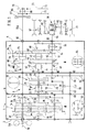
- Fig. 1 is the common housing 1 with the motor-side housing cover 2 and a first and second housing partition 3 and 4 and a rear side 5 of the housing 1 is shown schematically.
- the main group 8 can thus be completely assembled, in particular between the rear side 5 of the housing and the intermediate wall 4, before an intermediate gear 9 or an input group 7 is installed.
- the input group 7 also has a first countershaft 12 driving the main group 8 and a reversing shaft 13 for reverse travel.
- a power shift clutch CA, DB and GF designed as a double clutch, of the same type and size, the clutch bells 14, 15, 16 of which are rotatably mounted and which are directly or indirectly engaged with one another via external toothings. Namely, the clutch bell 14 is constantly engaged with both the clutch bell 15 and 16, but not the clutch bell 15 with clutch bell 16.
- the shafts of the input group 7 are arranged in an equilateral triangle and the external toothing of the clutch bell 15 runs on the external toothing the clutch bell 16 passes empty, but combs, as well as the external toothing of the clutch bell 16 with the external toothing of the clutch bell 14.
- Each clutch bell is axially divided into two identical friction plate packs by a radial web supporting it on its hub, which can be activated individually or jointly by means of pressurizing medium against opening spring forces by means of separate hydraulic pistons not specifically marked here are.
- the inner disk carriers can either be carried directly with the respective shaft 11, 12, 13, as in the power shift clutches B and G, or indirectly by a hub or hollow shaft rotatable on the respective shaft 11, 12, 13, as with the power shift clutches C, A , D and F.
- the hollow shaft carrying the inner disk carrier of clutch C is the input shaft 11, which is driven by a main drive shaft 10 via any vibration damper 11A as soon as the motor (not shown) is running.
- the input shaft 11 takes along a diameter of the clutch bell 14, which overrides the idler gear 17 on the drive side, and which drives the idler gear 18, which is connected upstream of the clutch bell 15 on the drive side, and the inner disk carrier of the powershift clutch D connected to it by a common hub on the countershaft 12 Connection is established.
- the clutch bell 14 On the output side, the clutch bell 14 is preceded by a further idler gear 19 connected to the inner disk carrier thereof by a common hub, which meshes with a fixed gear 20 that projects beyond the diameter of the clutch bell 15 on the countershaft 12 continuing into the main group 8 or with a primary shaft coaxial with it 32.
- the fixed gear 20 meshes with a smaller idler gear 21 provided on the reverse shaft 13 on the output side of the clutch bell 16 and connected to its inner disk carrier via a common hub.
- Fixed gear 20 is on the output side on countershaft 12 yet another, somewhat smaller fixed gear 22, which is in engagement with a fixed gear 23 fastened on the reversing shaft 13 and arranged downstream of the idler gear 21 on the output side, with a diameter that exceeds the diameter of the clutch bell 16.
- this fixed gear 23 also meshes with the idler gear 19 on the output side of the clutch bell 14 and a smaller idler gear 24 arranged downstream, which can be brought into positive engagement with the main drive shaft 10 by means of a sliding sleeve 25 and corresponding coupling teeth.
- the same sliding sleeve 25 can also produce a positive fit from the main drive shaft 10 to the idler gear 19 after the clutch bell 14 on the output side.
- This achieves a bypass drive connection that can be operated either forwards or backwards, depending on the position OV / OR, to bypass the powershift clutches dependent on functioning power and hydraulic supplies, thereby dragging or a mechanical Emergency driving operation via the gears of main group 8 becomes possible.
- This device with the wheels 22, 23, 24, 25 is not required when using form-locking or synchronous clutches in the input group 7, because then a power or hydraulic failure cannot lead to total blocking of the clutches.
- the intermediate gear 9 arranged axially between the input group 7 and a starting clutch 26 immediately upstream of the main group 8 in the example according to the invention can, if desired, be omitted without housing changes if no creeper or overdrive is required.
- the intermediate gear essentially consists of a small fixed gear 27 on the output side of the first intermediate housing wall 3 on the first countershaft 12, which drives a double gear 28, 29 on an intermediate shaft 30 parallel to the starting clutch 26, the ends of which are stored in the first and the second housing intermediate wall 3, 4.
- the double gear 28, 29 has a large drive-side and a small output-side gear 28 and 29 in the case of the creeper gear.
- the latter drives a large idler gear 31 on the primary shaft 32 of the starting clutch 26.
- This primary shaft 32 is aligned both coaxially with the countershaft 12 which has an axial bearing 33 (FIG. 3) in common, as well as with a secondary shaft 34 of the starting clutch 26.
- the primary shaft 32 is again by means of a further axial bearing 35 (FIG. 3) in front of the inner disk carrier of the starting clutch 26 within its housing supported or axially supported.
- Axially between the fixed gear 27 and the idler gear 31 is then a sliding sleeve 36 which is rotationally fixed with the primary shaft 32 and corresponding coupling teeth on the inner surfaces of the fixed and idler gear 27, 31 facing it.
- sliding sleeve 36 can effect a direct drive from there into primary shaft 32 without step-up or step-down, or - when acting on idler gear 31, cause a step-through or step-down drive through intermediate shaft 30 which all gear steps of the gear shaft transmission are enlarged or reduced in the selected ratio.
- the primary shaft 32 drives the clutch bell 37 of the starting clutch 26, which is designed as an outer disk carrier of a wet brake that is positively cooled when actuated, with inner disks 38 on the secondary shaft 34.
- this secondary shaft 34 is the drive-side end of the drive shaft 39 of the main group 8 protruding from the second housing partition 4.
- Die Idler gears mesh with fixed gears 48, 49, 50, 51 on a second countershaft serving as drive shaft 52 of main group 8, on the one end of which there is also a third synchronous clutch 53 with a rotationally fixed sleeve carrier and associated idler gears 54, 55, which with the two fixed gears 46, 47 comb on the drive shaft 39.
- the drive shaft 52 has an output gear 56, 57 at each of its two ends.
- the output-side shaft end protruding from the rear of the housing 5 drives a bevel gear, and this drives a bevel gear of a lockable axle differential 58 which on the one hand drives rear axle shafts 60 provided with brakes 59 with planetary gear drives 61.
- the driven gear 57 which protrudes from the second housing intermediate wall 4 on the drive side, is a spur gear that drives an idler gear 62 on a front axle drive shaft 63.
- the idler gear 62 also carries the clutch bell of a front axle engagement clutch 64 designed as an outer disk carrier.
- the inner disk carrier 65 is non-rotatably connected to the front axle drive shaft 63, which runs below the input group 7 and exits the housing cover 2 at its end face. There is still space in the intermediate axle gear 9 under the double gear 28, 29 in order to arrange a brake 66 on the front axle drive shaft 63 on the output side of the front axle engagement clutch 64, which is only indicated by dash-dotted lines in this diagram.
- the main drive shaft 10 located in the upper part of the housing 1 is surrounded by the input shaft 11 in the area of the input group 7. It continues outside the input group 7 as a solid shaft beyond the rear side 5 of the transmission and into a power take-off clutch 67 which can be designed as desired.
- the power take-off clutch 67 is a double clutch with a rotationally fixed sleeve carrier 68 and secondary loose wheels 69, 70 of different sizes, which are in engagement with fixed wheels 71, 72 of different sizes on a secondary shaft 73.
- Further various power take-offs can be connected directly to the section of the main drive shaft 10, which is free and gear-independent, on the output side. So z. B.
- the above-described PTO drive which can be driven at engine speed, optionally also by an output from a fast rotating fixed gear 51 on the output shaft 52 of the main group 8 via an idler gear 75 guided on a secondary shaft 74, an idler gear 76 which can be decoupled from the main drive shaft 10 and an associated sleeve carrier 77
- Shut-off clutch 78 is driven at the speed prevailing at the outlet of the main group and the outlet-side section of the main drive shaft separated from the main shaft 10 is used as a travel-dependent PTO shaft 10A.
- the central pump drive for the gear change transmission is also preferably arranged on the main drive shaft 10 above the main group 8, in that a fixed wheel 79 arranged upstream of the cut-off clutch 78 drives a counter wheel 80 which on the one hand drives the pump 81.
- All shafts 10, 10A, 12, 13, 30, 34 or 39, 52 and 63 are mounted in the housing intermediate walls 3, 4 or the rear of the housing 5 or the housing cover 2 in bearings 82 with low friction and from the shafts by means of holes in them Oil channels positively lubricated.
- the actuation of the clutches in the input group 7 is arbitrary per se, but is provided here by means of a rotary lever 112, 113 with gear selector 83 and integrated rocker switch 112 for work operations, as a result of which the positions for forward travel V, neutral N, reverse travel R in the steps for SLOW L , MEDIUM M, HIGH H and for FAST S, and if necessary and after releasing a lock, not shown here, the emergency drive circuit for forward V or reverse R proposed for power shift clutches can also be engaged with the same gear selector 83.
- the road gear selection via shift lever 84 can remain unchanged per se during work. If the intermediate gear 9 is installed, its connection clutch 36 can be placed in the crawl or overdrive gear via a further shift lever 85 with two end positions. All of these circuits can also be electrically or servo-actuated in a manner known per se, depending on the convenience. The automation of the power shift clutches is also possible at low additional costs.
- the input group 7 is designed with basically the same arrangement of the shafts 10, 11, 12, 13 as when it is equipped with power shift clutches, but without the mechanical emergency drive circuit.
- the drive connections for the double clutches C, A and D, B consist here only of mechanically actuable synchronizer clutches 18C and 20C, which, thanks to the design of the gear change transmission according to the invention, are also sufficient at medium moments and powers and are still easy to shift even when the creeper is engaged require less control effort than with power shift clutches.
- a reverse gear that is fully integrated into the input group 7 is engaged by engaging the synchronizer clutch 20C like the other gears and can therefore also be shifted just as easily in this embodiment.
- the main drive shaft 10 is not surrounded by a hollow shaft-like input shaft 11, but according to a simple vibration damper 11A as a solid shaft which directly drives the hubs of the fixed wheels 17A, 17B and 17C and which for a continuation shaft to a PTO connection in the area of the bearing 82 in the first housing intermediate wall 3 has a push-in socket connection 86 (see FIG. 3).
- the fixed gears 17A and 17B mesh with idler gears 18A and 18B on both sides of a sliding sleeve carrier fixed on the drive end of the first countershaft 12.
- the fixed gear 17C meshes with the idler gear 20A on the input side of the synchronizer clutch 20C on the output side.
- the reversing shaft 13 is here provided with a shaft end passing through its bearing 82 in the first intermediate wall 3 on which, when an intermediate gear 9 is installed, the shaft 30 thereof is mounted concentrically with the double gear 28, 29.
- a brake 66 is not held on a housing wall 3 or 4, but on the housing cover 2, so that radially under the intermediate shaft 30 space for a possibly larger double gear 28, 29 remains in the event that an overdrive translation is required.
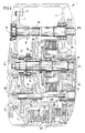
- FIG. 3 the interior of the housing of the first to second housing intermediate wall 3, 4, in which the starting clutch 26 is located, is shown constructively without the intermediate gear 9 provided there for optional installation.
- a free space 9A corresponding to its additional axial space requirement is left free.
- the main drive shaft 10 is guided in the first intermediate wall 3 of the housing in a bearing 82, in the neck 82A of which oil feed channels (not shown) to lubrication points and clutch cylinders etc. are located.
- the main drive shaft 10 ends in an externally toothed shaft stub, which is located approximately radially above the starting clutch 26 in a hollow end of the PTO shaft 10A in a rotationally fixed manner and thus represents an easily releasable push-in socket connection and facilitates the changes to the PTO shaft 10A.
- Another non-rotatable, but axially displaceable plug connection 87 with integrated axial and radial bearing 33 is provided in the connection from the first countershaft 12 to the secondary shaft 34 of the starting clutch 26.
- the secondary shaft 34 is rotatably inserted into a hollow end of the countershaft 12.
- a further plug-in sleeve 87 is pushed, which comprises a drive-side axial bearing 33 of the hub of the clutch bell 37 which it carries, which has 34 roller bearings 88 on the secondary shaft 34, from the outside.
- a plate spring 90 On the output side of the hub of the clutch bell serving as primary shaft 32 37 this lies axially against a support collar 89 on the secondary shaft 34.
- a plate spring 90 On its output side, a plate spring 90 abuts with its inner edge, the outer edge of which is spread apart in the output direction against a clutch pressure plate 91 which presses against a disk set 92 of the starting clutch 26.
- the outer plates are held by the clutch bell 37 rotatably.
- the clutch pressure plate 91 is axially loadable on its inner edge, counter to the plate spring 90 engaging in its outer third, by a plurality of bolts 93, which penetrate the inner disk carrier 94, which is held on the secondary shaft 34 in a rotationally fixed and immovable manner.
- actuating piston pressure plate 95 On the output side of the inner disk carrier 94, they are acted upon by an actuating piston pressure plate 95, which is assigned a further axial bearing 35 on the output side, against which the actuating piston 96 of the starting clutch 26 is pressed during the ventilation process.
- This is guided in an actuating cylinder ring body 97 which surrounds the primary shaft 34 and an annular actuating piston 96 which surrounds it and which is immovably embedded in the second intermediate housing wall 4 on the drive side in front of the bearing 82 of the drive shaft 39 of the main group 8.
- Both the clutch pressure line 98 for actuating the actuating piston 96 and a cooling oil line 99 enter the actuating cylinder body 97 from the second intermediate wall 4 of the housing.
- the latter opens into a pocket-shaped annular space 100 radially below the disk pack 92.
- the cooling oil can pass into the disk pack 92 in a manner known per se with increased pressure due to centrifugal forces with uniform distribution through radial bores in the jacket of the inner disk carrier 94 which are not specified.
- the flow duration and intensity of the cooling oil can thus be coupled to the axial travel of the actuating piston 96 or the associated pressure plate 95 by a metering device (not shown in particular) be that the cooling takes place only when the clutch 26 is closed.
- the actuating piston 96 is still loaded in the opening direction by a spiral spring 101 inserted into it approximately so far that the closing force of the plate spring 90 is not yet overcome.
- a special design with a particularly low mass was selected with the design described above, which does not require a rotating cylinder and allows a correspondingly light clutch bell 37 to be used.
- the secondary shaft 34 surrounded by the actuating cylinder body 97 together with internals and accessories is inserted on the output side thereof and radially under the associated bearing 82 into a hollow end of the drive shaft 39 of the main group 8 on the drive side and secured against rotation.
- the adjoining idler gear 42 meshes with the fixed gear 48 provided under the drive shaft 39 on the output shaft 52 of the main group 8 running parallel to it.
- Its drive-side end is supported in the second housing intermediate wall 4 with a bearing 82, from which it has a free end approximately like this protrudes far on the drive side, as the actuating cylinder body 97.
- a fixed drive wheel 57 is fastened on this free end of the output shaft 52 by means of internal teeth and an upstream shaft nut or the like.
- This fixed gear 57 drives an underlying fixed gear 62, which is fastened to a front axle drive shaft 63, has an opening cylinder 102 on the output side for the front axle connection clutch 64 and the inner disk carrier of which it is.
- a plurality of axially guided pistons 103 distributed around the circumference, which penetrate the web of the fixed gear 62 in the direction of the disk set 65, can bring this into positive engagement.
- the front axle drive shaft 63 can be driven via the clutch bell of the front axle connection clutch 64, on which the brake 66 is also arranged in the example, the outer plates of which are held in a brake housing 104 connected to the first intermediate wall 3 of the housing.
- the brake 66 is fully flooded in the sump of the gear housing 1 and is therefore well cooled.
- the connection of the brake housing 104 to the first housing intermediate wall 3 is designed as a shell-shaped bulge 105 which is open at the top and has a second wall region 106, which extends on the output side via the intermediate shaft 30, radially above the brake 66. This creates a second support option for the intermediate shaft 30, which is required especially when installing the intermediate gear 9.
- a separate oil pocket radially below the intermediate gear 9 then provides the same with particularly good splash lubrication.
- This oil channel 107 in the intermediate shaft 30 to that in the output shaft 52 of the main group 8, a connecting pipe 108 leading out of the intermediate shaft 30 is inserted into the drive-side end of the latter.
- Fig. 4 the same section of the gear change transmission as in Fig. 3 is shown again, but now with the intermediate gear installed instead of the push-in joint 87 9.
- this is designed as a creeper gear.
- a large idler gear 31 with only a slightly smaller diameter than that of the clutch bell 37 is rotatably mounted axially between the sleeve carrier and clutch bell 37.
- This idler gear 31 has the further corresponding coupling toothing for the sliding sleeve 36 on the sleeve carrier side.
- the wheel driven by the fixed gear 27 on the intermediate shaft 30 is of approximately the same diameter as the idler gear 31 and is integrally formed by its hub as a double gear 28, 29 with the smallest possible output pinion gear, which in turn meshes with the idler gear 31.
- the common hub can be rotated on the intermediate shaft 30 with needle bearings and laterally fixed by the first housing intermediate wall 3 on the one hand and the raised edge of the second wall region 106 on the other hand.
- the primary shaft 32 is no longer driven directly at the speed of the countershaft 12, but rather at a geared or step-down speed according to the gear ratios by the intermediate gear 9.
- the sliding sleeve 36 is simultaneously disengaged from the coupling teeth of the fixed gear 27.
- the idler gear 31 of the intermediate gear 9 is thus coupled and the drive shaft 39 of the main group 8 is driven correspondingly more slowly. If the sliding sleeve 36 remains out of engagement both with the clutch teeth of the fixed gear 27 and with the clutch teeth of the idler gear 31, the main group is 8 completely switched off and also the starting clutch 26 without drive.
- the sliding sleeve 36 remains in the coupling teeth of the fixed wheel 27, the wheels 28, 29, 31 rotate freely, but the frictional connection from the input group 7 to the main group 8 takes place directly and only via the sliding sleeve 36 and its sleeve carrier without any gearing or reduction .
- the sliding sleeve 36 is pushed in the output direction into the coupling teeth of the idler gear 31 and free from the fixed gear 27, so that the drive connection via the double gear 28, 29 to the clutch bell 26 is activated.
- the axial distance from the primary shaft 32 required for installing an intermediate gear 9 corresponds approximately to the overall length of a single gear 27 because the sliding sleeve 36 and idler gear 31 are carried by the hub of the clutch bell 37, which is required anyway.
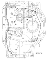
- the input shaft 11 and the main drive shaft 10 enclosed by it are provided in the upper half of the housing somewhat to the left of the geometric center within the intermediate wall 3 of the housing, which also has bearings 82 of the shafts 12, 13.
- the center distances of the shafts 11, 12, 13 form an equilateral triangle, in which the countershaft 12 in the viewing direction to the right of the vertical through the input shaft 11 makes an overhang necessary for the approximately rectangular format of the housing 1.
- the reversing shaft 13 lies only insignificantly to the left of the vertical through the input shaft 11 and somewhat lower than the countershaft 12.
- the center of the front axle drive shaft 63 is located exactly perpendicularly below the input shaft 11, but below the lower edge of the first housing intermediate wall 3. So z. B. when renewing synchronizer clutches in the input group 7, neither the front axle drive shaft 63 nor the main group 8 or the starting clutch 26 are removed. The left side of the transmission housing 1 in the direction of travel remains free with this arrangement for attachments such as tanks, etc., while the opposite side offers favorable lateral access options such. B. to the pump 81 or the other power take-off z. B. 74 ... 78 within the housing 1 and no major gear parts hinder such inspection work, etc.
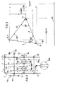
- FIG. 6 the spacing relationships in the vertical V and the horizontal H of the shafts 10, 11, 12, 13, 52, 63 to one another show which structural measures have been taken to ensure both the same speeds for forward and reverse travel as well as favorable ones Achieve gear ratios and compact installation space.
- the axis of the main drive shaft 10 and the hollow shaft-like input shaft 11 is shown in dash-dotted lines at the top of the figure. From there, the vertical distance to the countershaft is assumed to be V. Then the vertical distance from the input shaft 11 to the reversing shaft 13 is approximately V x 1.73 and to the output shaft 52 is approximately V x 1.50 and to the front axle drive shaft 63 is approximately V x 3.11.
- the ratio of the horizontal distances H from the reversing shaft 13 to the input shaft 11 and to the countershaft 12 is approximately 1: 9.9.
- the position of the input, countershaft and reversing shafts is indicated by this and by specifying 60 ° angles for the driving force curves for forward and reverse R. Accordingly, the centers of these waves 10, 11, 12 and 13 form an equilateral triangle standing on a tip.
- the positions of the output shaft 52 of the main group 8 and the front axle drive shaft 63 are not influenced by this or can be selected as desired. As beneficial however, a distance for the front axle 63 of the input shaft of approximately V x 3.11 was determined for the latter.
- FIG. 7 and 8 show a one-hand drive switch which is favorable for carrying out the switching operations in the gear change transmission according to FIG. 1.
- This has a housing 110 for installation in a console 111, which guides a turning lever 112, in the handle 113 of which a multi-stage rocker switch 114 is embedded.
- a locking spring 115 above or below the housing 110 fixes the selected settings.
- At the lower end of the lever 112 are the usual connections for mechanical (linkages, Bowden cables, etc.) and electrical (cable) actuations 116, 117.
- the lever 112 has the neutral position N in the vertical direction and the forward driving position V in about 20 ° and the reverse driving position T in about 20 ° backwards.
- the rocker switch 114 has a springback in the middle position from both operating directions (+/- ) and can also be deflected by a maximum of approx. 20 ° in both directions. After approx. 7 ° there is contact with approx. 2 ° overtravel.
- the associated circuit diagram is shown in FIG. 8.
- the position "zero" which can be obtained by indenting from the side, applies to the case where the mechanical emergency drive circuit is used via the form-locking clutch 25 in the event of hydraulic or / and electricity failure in an input group equipped with power-operated clutches.
- the switching sequence for the input group 8 is shown in table form in FIG. 9.
- the fields marked with dots show which powershift clutches (A to G) of the input group 7 are to be activated in each case by the above-described reversing lever 112 or the rocker switch 114. All of these gears can be engaged in each of the two directions of travel V and R in each of the gears 1 to 6 of the main group 8 by means of a separate mechanical gear lever, not shown here.
- Another lever or switch, not shown in the construction, is provided for the creep gear CR, which simultaneously locks the lever of the main group 8 for the gears 5 and 6 when actuated.
- the positions of the rocker switch 114 L, M, H, S correspond to the terms for "SLOW”, “MEDIUM”, “HIGH” and “FAST". Since it is embedded in the mechanical lever 112, the driver can keep one hand on the steering wheel in spite of the large number of gears in individual gear shifts.
- 24 forward and 24 reverse gears at normal speeds and, when using the creeper or overdrive intermediate stage, another 16 forward and reverse gears, or when using the overdrive intermediate stage 9, another 24 forward gears each. and reverse gears can be selected.
- a very jerky and powerful driving style e.g. B. for plowing in the field as well as fast driving for the road, which corresponds to a speed range of about 0.3 km / h to about 60 km / h.
Landscapes
- Engineering & Computer Science (AREA)
- General Engineering & Computer Science (AREA)
- Mechanical Engineering (AREA)
- Chemical & Material Sciences (AREA)
- Combustion & Propulsion (AREA)
- Transportation (AREA)
- Structure Of Transmissions (AREA)
- Gear Transmission (AREA)
- Retarders (AREA)
Claims (25)
- Boîte à vitesses multiples à engrenages, contenue par un carter (1) pourvu d'un couvercle (2), de cloisons intermédiaires (3, 4) et d'un côté arrière (5),- avec un embrayage de démarrage (26) et plusieurs groupesrelais (7, 8) du type à renvoi,- dont un groupe principal (8) à étagement large et à embrayages synchronisés sert de groupe de changement de gammes pour choisir la gamme de régimes voulue- et un groupe d'entrée (7) à étagement serré, disposé en amont du groupe principal, sert de groupe de subdivision pour la sélection fine des régimes à l'intérieur d'une gamme de régimes,- où un premier arbre de renvoi (12) du groupe d'entrée (7) est aligné axialement avec un arbre entraîneur (39) du groupe principal (8)- et où un arbre entraîneur principal et un arbre d'entrée (10, 11) sont décalés et parallèles par rapport au premier arbre de renvoi (12)- et peuvent être accouplés à un arbre de prise de mouvement (73) pour l'entraîner,
caractérisée :- en ce que l'arbre entraîneur principal (10) passe le long du groupe principal (8), l'arbre de prise de mouvement (73) étant prévu dans la zone du côté arrière (5) du carter,- en ce que l'embrayage de démarrage (26) est disposé, dans l'espace et dans la chaîne cinématique, entre le premier arbre de renvoi (12) et l'arbre entraîneur (39),- et en ce que l'embrayage de démarrage (26) comporte un paquet de disques (92) à refroidissement forcé à huile, où le flux d'huile peut être arrêté lorsque l'embrayage de démarrage est ouvert. - Boîte selon la revendication 1, caractérisée :- en ce qu'il est prévu dans le groupe d'entrée (7), parallèlement au premier arbre de renvoi (12), un arbre d'inversion (13)- qui est équipé d'au moins un pignon fixe (23, 23A) et d'un autre pignon fou (21) ou fixe (21A),- dont le pignon fixe (23, 23A) est en liaison motrice permanente avec l'arbre entraîneur principal ou arbre d'entrée (10, 11)- et l'autre pignon (21, 21A) peut être mis en liaison motrice avec un arbre primaire (32) de l'embrayage de démarrage (26) au moyen d'un embrayage commutable en charge (F) ou synchronisé (20C), disposé à l'intérieur du groupe d'entrée (7).
- Boîte selon la revendication 1, caractérisée en ce que chaque arbre (10, 11; 12; 13) du groupe d'entrée (7) porte une cloche d'embrayage respective (14, 15, 16) d'embrayages commutables en charge (A, C; B, D; F, G) qui sont alignés verticalement les uns avec les autres.
- Boîte selon la revendication 2, caractérisée :- en ce que les embrayages synchronisés (18C, 20C) ou commutables en charge (B, C) du groupe d'entrée (7) peuvent être actionnés au moyen d'un sélecteur de vitesses commun (83A),- où ces embrayages, avec les pignons fous (18A, 18B; 20A, 20B) qui leurs sont associés, sont juxtaposés sur le premier arbre de renvoi (12) et ont chacun deux positions de prise,- où, dans au moins une position de prise sur un pignon fou (20B), l'arbre d' inversion (13) peut être mis en liaison motrice avec l'arbre primaire (32) de l'embrayage de démarrage (26) pour servir à la marche arrière.
- Boîte selon l'une des revendications 1 à 4, caractérisée en ce que tous les embrayages commutables en charge ou synchronisés (A...G; 18C, 20C) se trouvant dans le groupe d'entrée (7), lesquels sont servocommandés au moyen d'un sélecteur de vitesses commun (83, 83A), sont associés à un entraînement de secours (24, 25) à fonctionnement purement mécanique pour la marche avant et la marche arrière.
- Boîte selon la revendication 5, caractérisée :- en ce que l'entraînement de secours (24, 25) comporte un embrayage positif (25) disposé sur l'arbre entraîneur principal ou arbre d'entrée (10, 11) et actionné manuellement indépendamment du sélecteur de vitesses (83, 83A)- et qui met en prise, selon le sens de marche, soit un pignon fou (19) disposé du côté d'entrée sur l'arbre entraîneur principal ou arbre d'entrée (10, 11) et un pignon fixe (20) disposé sur le premier arbre de renvoi (12) ou l'arbre primaire (32) de l'embrayage de démarrage (26), soit un pignon fou (24), disposé du côté de la sortie et en liaison motrice avec l'arbre primaire (32), et un manchon baladeur de l'embrayage positif (25), ce manchon étant entraîné par un porte-manchon solidaire en rotation de l'arbre (10, 11).
- Boîte selon la revendication 1, caractérisée en ce que l'arbre d'entrée (11) est agencé en arbre creux entraîné par l'arbre entraineur principal (10) au moyen d'un dispositif amortisseur de vibrations (11A) et disposé concentriquement sur ledit arbre principal et parallèlement au-dessus du premier arbre de renvoi (12).
- Boîte selon la revendication 1, caractérisée :- en ce que les embrayages synchronisés (40, 41, 53) prévus dans le groupe principal (8) sont formés par des embrayages doubles comportant chacun un porte-manchon fixe en rotation sur leur arbre (39, 52) entre deux pignons fous (42, 43; 44, 45; 54, 55) de différentes tailles pourvus de dentures d' accouplement,- ces pignons fous étant eux-mêmes engrenés en permanence sur les pignons correspondants de différentes tailles (pignons fixes 48, 49; 50, 51; 46, 47), solidaires en rotation de l'arbre parallèle correspondant (39, 52).
- Boîte selon la revendication 1, caractérisée en ce que l'arbre entraîneur principal ou arbre d'entrée (10, 11), le premier arbre de renvoi (12) et l'arbre d'inversion (13) sont montés dans le groupe d'entrée (7) selon une disposition en triangle à côtés égaux (R).
- Boîte selon la revendication 3, caractérisée :- en ce que pour chaque cloche d'embrayage (14, 15, 16) du groupe d'entrée (7), il est prévu un embrayage double identique (C, A; D, B; G, F) par arbre (11, 12, 13),- où une denture extérieure de la cloche d' embrayage (14) est engrenée en permanence à la fois sur une denture extérieure de la cloche d'embrayage (15) et sur une denture extérieure de la cloche d'embrayage (16),- tandis que la denture extérieure de la cloche d' embrayage (16) est raccourcie axialement de façon à ne pas être engrenée sur la cloche d'embrayage (15).
- Boîte selon la revendication 3, caractérisée :- en ce que, devant les deux côtés de l'embrayage commutable en charge (C, A) disposé sur l'arbre entraîneur principal et l'arbre d'entrée (10, 11), il est prévu extérieurement des pignons respectifs de différentes tailles (17, 19) dont chacun est solidaire en rotation respectivement de l'un des porte-disques intérieurs dudit embrayage (C, A), où le pignon (17) est un pignon fixe de l'arbre d'entrée et le pignon (19) est un pignon fou de l'arbre entraîneur principal (10),- en ce qu'un pignon fou (18) est disposé devant le côté d'entrée de l'embrayage commutable en charge (D, B) disposé sur le premier arbre de renvoi (12), et deux pignons fixes de différentes tailles (20, 22) sont disposés coaxialement derrière le côté de sortie dudit embrayage,- dont le pignon fou (18) du côté d'entrée et le pignon fixe (20), plus proche de l' embrayage, du côté de sortie sont solidaires en rotation respectivement chacun de l'un des porte-disques intérieurs dudit embrayage (D, B),- en ce que, seulement du côté de sortie de l'embrayage commutable en charge (G, F) disposé sur l'arbre d' inversion (13), il est prévu extérieurement un pignon fou (21) et un pignon fixe (23) de différentes tailles dont le pignon (21) le plus proche de l'embrayage est solidaire en rotation d'un premier porte-disques intérieur dudit embrayage (F) au moyen d'un court arbre creux, et le pignon (23) le plus éloigné de l'embrayage est solidaire en rotation d'un autre porte-disques intérieur dudit embrayage (G) au moyen de l'arbre d'inversion (13) traversant l'arbre creux,- et en ce que le pignon fixe (17) de l'arbre d'entrée (11) et le pignon fou (19) de l'arbre entraîneur principal (10) sont engrenés en permanence respectivement sur le pignon fou (18) du côté d'entrée et sur le pignon fixe (20) plus proche de l' embrayage, du premier arbre de renvoi (12) du côté de sortie, et- en ce que le pignon fou (21) et le pignon fixe (23) de l'arbre d'inversion (13) sont aussi engrenés sur les deux pignons fixes (20, 22) du premier arbre de renvoi (12).
- Boîte selon la revendication 1 caractérisée :- en ce qu'un espace libre (9A) pour le montage optionnel d'une boîte intermédiaire (9) est prévu axialement entre la première cloison intermédiaire (3), située du côté de la sortie du groupe d'entrée (7), et l'embrayage de démarrage (26),- en ce que la boîte intermédiaire (9) est une boîte à vitesses extra-lentes ayant en entrée un pignon fixe (27) approximativement du diamètre d'un moyeu de l'embrayage de démarrage (26),- et en ce que la moitié d'entrée, engrenée sur ce pignon fixe (27), d'un pignon double (28, 29) tournant sur un arbre intermédiaire (30) a un diamètre d'au moins 1,6 fois celui dudit pignon fixe (27).
- Boîte selon la revendication 12, caractérisée:- en ce qu'un embrayage de commutation de la boîte intermédiaire (9) est un embrayage synchronisé ayant des surfaces de friction et des crabots des deux côtés,- et en ce que le manchon baladeur (36) de cet embrayage transmet dans sa position du côté de l'entrée, un flux de forces direct non démultiplié et, dans sa position du côté de la sortie, un flux de forces indirect surmultiplié ou démultiplié de l'arbre de renvoi (12) à l'arbre primaire (32) de l'embrayage de démarrage (26) ou à l'arbre entraîneur (39) du groupe principal (8).
- Boîte selon la revendication 12, caractérisée:- en ce que la première cloison intermédiaire (3) comporte dans sa zone inférieure une partie incurvée (105) en forme de coque ouverte vers le haut, ayant du côté de la sortie une seconde zone de paroi (106) qui remonte- et en ce que le pignon double (28, 29) prévu sur l'arbre intermédiaire (30) de la boîte intermédiaire (9) est entouré en dessous par ladite partie incurvée (105),- l'arbre intermédiaire (30) étant supporté à la fois dans la première cloison intermédiaire (3) et dans ladite seconde zone de paroi (106) de ladite partie incurvée (105).
- Boîte selon la revendication 12, caractérisée :- en ce que l'arbre entraîneur (39) du groupe principal (8) enjambe en une pièce l'espace libre (9A) prévu pour le montage de la boîte intermédiaire (9), de la deuxième à la première cloison intermédiaire (4, 3),- et en ce que l'élément monté fou sur cet arbre et servant à la fois de porte-disques extérieur de la cloche d'embrayage (37) et d'arbre primaire (32) est guidé axialement au moyen d'un palier axial (33, 35) de chaque côté, entre ses faces frontales et un collet radial d'appui (89) du côté de la sortie de l' arbre secondaire (34), ainsi qu'une face frontale du côté d'entrée du moyeu environnant du pignon fixe de sortie (22) du premier arbre de renvoi (12).
- Boîte selon la revendication 8, caractérisée :- en ce que le groupe principal (8) est pourvu des deux embrayages synchronisés (40, 41) actionnés par deux manchons baladeurs ainsi que des pignons fous correspondants (42, 43 et 44, 45) sur l'arbre entraîneur (39) et du troisième embrayage synchronisé (53) de même construction sur l'arbre de sortie (52),- où les pignons fous (42, 43 et 44, 45) de l'arbre entraîneur (39) sont en liaison motrice avec des pignons fixes (48, 49 et 50, 51) de l'arbre de sortie (52), et les pignons fous (54, 55) de l'arbre de sortie (52) sont en liaison motrice avec des pignons fixes (46, 47) de l'arbre entraîneur (39).
- Boîte selon la revendication 1, caractérisée :- en ce qu'il est prévu, sur un arbre secondaire (34) de l' embrayage de démarrage (26) lequel est solidaire en rotation de l'arbre entraîneur (39) du groupe principal (8), un flasque radial portant un porte-disques intérieur (94) s'étendant du côté de la sortie et pourvu de trous radiaux (94A) en direction du paquet de disques (92)- et en ce qu'un canal à huile (99) situé dans la deuxième cloison intermédiaire (4) débouche horizontalement dans une poche annulaire (100) ménagée à l'intérieur du porte-disques intérieur (94), cette poche étant délimitée axialement par le flasque radial et ouverte du côté du groupe principal,- ledit canal étant alimenté en combinaison avec des opérations de fermeture de l' embrayage de démarrage (26) pour produire un refroidissement forcé, au moyen d'une amenée de lubrifiant couplée à la commande de l'embrayage de démarrage (26).
- Boîte selon la revendication 1, caractérisée :- en ce que l'arbre de sortie (52) du groupe principal (8) comporte, sur une extrémité émergeant en direction de l'entrée hors de son palier (82) disposé dans la deuxième cloison intermédiaire (4), un pignon fixe (57) bloqué par un écrou d'axe,- lequel s'engrène sur un pignon fou (62) d'un embrayage de traction avant disposé sur un arbre (63) d'entraînement d'essieu avant qui comporte des paliers (82) à la fois dans la deuxième (4) et la première (3) paroi intermédiaire,- où un flasque du pignon fou (62) contient un vérin hydraulique (102) à piston pour ouvrir le paquet de disques à l' encontre d'un ressort à diaphragme et où les disques extérieurs d'une cloche d'embrayage (64) servant de porte-disques sont supportés par le moyeu de celle-ci sur l'arbre d' entraînement d' essieu avant (63).
- Boîte selon la revendication 18, caractérisée :- en ce que l'embrayage de traction avant est suivi d'un frein (66) pourvu de deux pistons à écartement entre deux paquets de disques,- dont les disques intérieurs sont solidaires en rotation de l'arbre d' entraînement d' essieu avant (63) et dont les disques extérieurs sont non rotatifs dans un carter de frein (104) supporté par la première cloison intermédiaire (3).
- Boîte selon la revendication 1, caractérisée en ce qu'un pignon fixe (79) est entraîné par l'arbre entraîneur principal ou arbre d'entrée (10, 11) du côté de sortie du groupe d'entrée (7) et s'engrène sur un pignon (80) appartenant à un entraînement parallèle d'une pompe (81).
- Boîte selon la revendication 1, caractérisée en ce qu'il est prévu, dans la zone qui suit l'arbre d'entrée (11) du côté de la sortie, un embrayage de connexion (67) suivi d'un double embrayage de commutation (68) pour entraîner un arbre de prise de mouvement (73) par des liaisons motrices alternatives au moyen de deux pignons de sortie (71, 72) de tailles différentes sur l'arbre de prise de mouvement.
- Boîte selon la revendication 1, caractérisée en ce que le niveau d'huile dans le carter (1) est prévu plus bas que l'axe central de l'arbre de sortie (52) du groupe principal (8).
- Boîte selon la revendication 1, caractérisée :- en ce que les arbres de tous les groupes sont pourvus d'alésages de passage d'huile (107) conduisant à des points de lubrification ou aux vérins d' actionnement des embrayages commutables en charge (A, B, C, D, F, G),- ces alésages étant reliés à des raccords d' entrée par des gorges annulaires ménagées dans les cloisons intermédiaires (2, 3, 4) et des alésages radiaux sortant des arbres.
- Boîte selon la revendication 1, caractérisée :- en ce que les embrayages commutables en charge (C, A) disposés sur l'arbre entraîneur principal ou arbre d'entrée (10, 11) sont commandés au moyen d'alésages de passage d'huile (107) à partir d'un collet annulaire d'amenée d'huile ménagé dans la première cloison intermédiaire (3) près du palier (82) situé du côté de l'arbre de prise de mouvement- et en ce que les embrayages commutables en charge (D, B et G, F), disposés sur le premier arbre de renvoi (12) et sur l'arbre d' inversion (13) du groupe d'entrée (7) sont commandés au moyen d'alésages de passage d'huile (107) à partir de collets annulaires d'amenée d'huile dans les paliers (82) disposés dans le couvercle frontal (2) du carter, et- en ce que l' embrayage de démarrage (26), disposé en amont de l'arbre entraîneur (39) du groupe principal (8), est commandé hydrauliquement à travers un conduit de pression (98) disposé dans la deuxième cloison intermédiaire (4).
- Boîte selon la revendication 1, caractérisée en ce que la première cloison intermédiaire (3) est ajustée dans une ouverture du carter et est fixée par des vis contre un flasque (6) à l'intérieur du carter (1) indépendamment des papliers (82) des arbres (39 et 52) du groupe principal (8).
Applications Claiming Priority (3)
| Application Number | Priority Date | Filing Date | Title |
|---|---|---|---|
| DE3922053 | 1989-07-05 | ||
| DE3922053 | 1989-07-05 | ||
| PCT/EP1990/001056 WO1991000445A1 (fr) | 1989-07-05 | 1990-07-02 | Boite de vitesse a engrenages a etages multiples |
Publications (2)
| Publication Number | Publication Date |
|---|---|
| EP0481014A1 EP0481014A1 (fr) | 1992-04-22 |
| EP0481014B1 true EP0481014B1 (fr) | 1995-02-22 |
Family
ID=6384323
Family Applications (2)
| Application Number | Title | Priority Date | Filing Date |
|---|---|---|---|
| EP90909698A Expired - Lifetime EP0480955B1 (fr) | 1989-07-05 | 1990-06-29 | Boite de vitesses a pignons et a etages multiples |
| EP90917792A Expired - Lifetime EP0481014B1 (fr) | 1989-07-05 | 1990-07-02 | Boite de vitesse a engrenages a etages multiples |
Family Applications Before (1)
| Application Number | Title | Priority Date | Filing Date |
|---|---|---|---|
| EP90909698A Expired - Lifetime EP0480955B1 (fr) | 1989-07-05 | 1990-06-29 | Boite de vitesses a pignons et a etages multiples |
Country Status (5)
| Country | Link |
|---|---|
| US (2) | US5239887A (fr) |
| EP (2) | EP0480955B1 (fr) |
| AT (2) | ATE113700T1 (fr) |
| DE (2) | DE59007649D1 (fr) |
| WO (2) | WO1991000444A1 (fr) |
Cited By (2)
| Publication number | Priority date | Publication date | Assignee | Title |
|---|---|---|---|---|
| DE102011080565A1 (de) | 2011-08-08 | 2013-02-14 | Zf Friedrichshafen Ag | Eingangsgruppe eines Zahnräderwechselgetriebes |
| DE102016225255A1 (de) * | 2016-12-16 | 2018-06-21 | Zf Friedrichshafen Ag | Anordnung zum Schmieren eines Getriebes, Kraftfahrzeuggetriebe und Kraftfahrzeug |
Families Citing this family (26)
| Publication number | Priority date | Publication date | Assignee | Title |
|---|---|---|---|---|
| BR9008039A (pt) * | 1990-08-31 | 1993-07-06 | Zahnradfabrik Friedrichshafen | Engrenagem de mudanca de rodas dentadas,de varios estagios |
| WO1992004561A1 (fr) * | 1990-08-31 | 1992-03-19 | Zahnradfabrik Friedrichshafen Ag | Boite de vitesses a engrenages a etages multiples |
| SE467426B (sv) * | 1990-11-01 | 1992-07-13 | Volvo Ab | Motorfordonsvaexellaada |
| US5573471A (en) * | 1995-03-17 | 1996-11-12 | Case Corporation | Transmission for an off-highway implement |
| DE19837776A1 (de) * | 1998-08-20 | 2000-02-24 | Zahnradfabrik Friedrichshafen | Getriebe mit nicht-koaxialem Abtrieb |
| JP4201228B2 (ja) * | 1999-06-14 | 2008-12-24 | 株式会社 神崎高級工機製作所 | 作業車両のトランスミッション |
| US6176803B1 (en) | 1999-09-28 | 2001-01-23 | Caterpillar Inc. | Transmission assembly with four planetary gear sets providing nine forward and one reverse gear ratio |
| JP2001227598A (ja) | 2000-02-16 | 2001-08-24 | Jatco Transtechnology Ltd | クラッチ配設構造及び該クラッチ配設構造を用いた変速機 |
| JP2002098168A (ja) * | 2000-09-22 | 2002-04-05 | Nsk Warner Kk | 発進クラッチ及びその制御方法 |
| JP4133668B2 (ja) * | 2003-08-07 | 2008-08-13 | 本田技研工業株式会社 | 平行軸式変速機 |
| US20050233287A1 (en) * | 2004-04-14 | 2005-10-20 | Vladimir Bulatov | Accessible computer system |
| DE102006024370A1 (de) * | 2006-05-24 | 2007-12-13 | Zf Friedrichshafen Ag | Mehrgruppengetriebe und Verfahren zum Gangwechsel bei einem Mehrgruppengetriebe |
| DE102007003340A1 (de) * | 2007-01-17 | 2008-07-24 | Deere & Company, Moline | Getriebe |
| JP2008208912A (ja) * | 2007-02-26 | 2008-09-11 | Kanzaki Kokyukoki Mfg Co Ltd | 作業車用変速機構 |
| DE102008002296A1 (de) * | 2008-06-09 | 2009-12-10 | Zf Friedrichshafen Ag | Mehrgruppengetriebe eines Kraftfahrzeuges |
| GB0910242D0 (en) * | 2009-06-15 | 2009-07-29 | Bamford Excavators Ltd | Hybrid transmission |
| KR20110017216A (ko) * | 2009-08-13 | 2011-02-21 | 류승범 | 자동차의 수동변속기용 입출력 샤프트의 진동흡수장치 |
| DE102012216227A1 (de) * | 2012-09-13 | 2014-03-13 | Zf Friedrichshafen Ag | Gehäuse für eine Erweiterungsstufe, Erweiterungsstufe, Getriebe und Antriebsstrang für ein Fahrzeug |
| US8984973B1 (en) * | 2013-11-07 | 2015-03-24 | Agco International Gmbh | Multiple speed power take off |
| JP6305265B2 (ja) * | 2014-08-01 | 2018-04-04 | 株式会社クボタ | 走行作業車 |
| DE102015211049A1 (de) * | 2015-06-16 | 2016-12-22 | Zf Friedrichshafen Ag | Getriebeanordnung, Gesamtgetriebe und landwirtschaftliche Arbeitsmaschine |
| US10557524B2 (en) * | 2016-10-18 | 2020-02-11 | Textron Innovations Inc. | Gearing system for compound gear reduction |
| AT525268B1 (de) * | 2021-09-29 | 2023-02-15 | Avl List Gmbh | Getriebeanordnung mit 5 losrädern im power-shift-getriebe |
| EP4409160B1 (fr) | 2021-09-29 | 2025-11-05 | AVL List GmbH | Ensemble transmission |
| AT525267B1 (de) * | 2021-09-29 | 2023-02-15 | Avl List Gmbh | Getriebeanordnung mit 6 losrädern im power-shift-getriebe |
| IT202300001881A1 (it) * | 2023-02-06 | 2024-08-06 | Cnh Ind Italia Spa | Architettura di trasmissione a doppia frizione per veicoli agricoli |
Family Cites Families (22)
| Publication number | Priority date | Publication date | Assignee | Title |
|---|---|---|---|---|
| US2975656A (en) * | 1958-04-21 | 1961-03-21 | Haverlender Karl | Change-speed gear unit for motor vehicles |
| DE2219242C2 (de) * | 1972-04-20 | 1985-02-14 | Klöckner-Humboldt-Deutz AG, 5000 Köln | Zahnräderwechselgetriebe in Gruppenbauweise für straßen und/oder geländegängige Sonderfahrzeuge |
| DE2244342A1 (de) * | 1972-09-09 | 1974-03-21 | Kloeckner Humboldt Deutz Ag | Zahnraederwechselgetriebe in gruppenbauweise insbesondere fuer land- und/oder bauwirtschaftlich nutzbare motorfahrzeuge |
| DE2405023C2 (de) * | 1974-02-02 | 1982-07-08 | Klöckner-Humboldt-Deutz AG, 5000 Köln | Zahnräderwechselgetriebe in Gruppenbauart für Kraftfahrzeuge, insbesondere für Land- und/oder bauwirtschaftlich nutzbare Kraftfahrzeuge |
| US4116090A (en) * | 1974-03-02 | 1978-09-26 | Klockner-Humboldt-Deutz Aktiengesellschaft | Change gear transmission in group arrangement, especially for motor vehicles for use in agriculture and in the construction field |
| DE2645907C3 (de) * | 1976-10-12 | 1982-04-08 | Xaver Fendt & Co, 8952 Marktoberdorf | Zahnräderwechselgetriebe |
| DE2645957A1 (de) * | 1976-10-12 | 1978-04-13 | Fendt & Co Xaver | Zahnraederwechselgetriebe in gruppenbauweise |
| JPS53134156A (en) * | 1977-04-27 | 1978-11-22 | Kubota Ltd | Transmission of tractor |
| AU528214B2 (en) * | 1979-11-13 | 1983-04-21 | Kubota Ltd. | Vehicle transmission drive system |
| AU548398B2 (en) * | 1982-09-03 | 1985-12-12 | Iseki & Co. Ltd. | Gear casing |
| ATE22975T1 (de) * | 1983-01-05 | 1986-11-15 | Deere & Co | Wechselgetriebe fuer kraftfahrzeuge. |
| US4640146A (en) * | 1983-04-25 | 1987-02-03 | Massey-Ferguson Inc. | Multiratio constant mesh change speed transmission |
| EP0188411B1 (fr) * | 1983-09-15 | 1987-09-30 | ZF FRIEDRICHSHAFEN Aktiengesellschaft | Engrenage commutable en charge |
| US4539856A (en) * | 1983-09-23 | 1985-09-10 | Doug Nash Equipment & Engineering | Two-speed auxiliary transmission |
| US4777837A (en) * | 1985-07-06 | 1988-10-18 | Zahnradfabrik Friedrichshafen, Ag. | Power shiftable transmission for vehicle |
| US4757726A (en) * | 1985-08-19 | 1988-07-19 | Mazda Motor Corporation | Vehicle gear transmission having an overdrive gear stage |
| NZ215776A (en) * | 1985-08-20 | 1988-04-29 | Kubota Ltd | Transmission case for tractor, removable housing for supplementary unit |
| AU572741B2 (en) * | 1986-03-03 | 1988-05-12 | Kubota Ltd. | Transmission for working vehicle with an overtop drive |
| US4794807A (en) * | 1986-06-12 | 1989-01-03 | Kubota, Ltd. | Tractor transmission |
| DE3633372A1 (de) * | 1986-10-01 | 1988-04-14 | Deere & Co | Verfahren zum schalten eines aus mehreren getriebeeinheiten bestehenden getriebes |
| US4785682A (en) * | 1987-05-20 | 1988-11-22 | Honda Giken Kogyo Kabushiki Kaisha | Power transmission device |
| JPH01303340A (ja) * | 1988-05-31 | 1989-12-07 | Fuji Heavy Ind Ltd | 縦置式エンジンにおける自動変速機 |
-
1990
- 1990-06-29 DE DE59007649T patent/DE59007649D1/de not_active Expired - Lifetime
- 1990-06-29 WO PCT/EP1990/001040 patent/WO1991000444A1/fr not_active Ceased
- 1990-06-29 EP EP90909698A patent/EP0480955B1/fr not_active Expired - Lifetime
- 1990-06-29 US US07/778,844 patent/US5239887A/en not_active Expired - Fee Related
- 1990-06-29 AT AT90909698T patent/ATE113700T1/de not_active IP Right Cessation
- 1990-07-02 EP EP90917792A patent/EP0481014B1/fr not_active Expired - Lifetime
- 1990-07-02 DE DE59008546T patent/DE59008546D1/de not_active Expired - Lifetime
- 1990-07-02 WO PCT/EP1990/001056 patent/WO1991000445A1/fr not_active Ceased
- 1990-07-02 US US07/781,217 patent/US5301564A/en not_active Expired - Fee Related
- 1990-07-02 AT AT90917792T patent/ATE118864T1/de not_active IP Right Cessation
Cited By (2)
| Publication number | Priority date | Publication date | Assignee | Title |
|---|---|---|---|---|
| DE102011080565A1 (de) | 2011-08-08 | 2013-02-14 | Zf Friedrichshafen Ag | Eingangsgruppe eines Zahnräderwechselgetriebes |
| DE102016225255A1 (de) * | 2016-12-16 | 2018-06-21 | Zf Friedrichshafen Ag | Anordnung zum Schmieren eines Getriebes, Kraftfahrzeuggetriebe und Kraftfahrzeug |
Also Published As
| Publication number | Publication date |
|---|---|
| EP0480955A1 (fr) | 1992-04-22 |
| US5301564A (en) | 1994-04-12 |
| EP0480955B1 (fr) | 1994-11-02 |
| WO1991000444A1 (fr) | 1991-01-10 |
| ATE118864T1 (de) | 1995-03-15 |
| ATE113700T1 (de) | 1994-11-15 |
| DE59007649D1 (de) | 1994-12-08 |
| EP0481014A1 (fr) | 1992-04-22 |
| WO1991000445A1 (fr) | 1991-01-10 |
| DE59008546D1 (de) | 1995-03-30 |
| US5239887A (en) | 1993-08-31 |
Similar Documents
| Publication | Publication Date | Title |
|---|---|---|
| EP0481014A1 (fr) | Boite de vitesse a engrenages a etages multiples. | |
| EP0834027B1 (fr) | Transmission a derivation de puissance hydrostatique--mecanique | |
| DE69825374T2 (de) | Getriebemechanismus für ein Arbeitsfahrzeug | |
| DE102008023784B4 (de) | Neun- oder Zehngang-Vorgelegewellen-Automatikgetriebe mit aufgeteilter Kupplung | |
| EP2914874B1 (fr) | Transmission à double embrayage | |
| EP2116411A1 (fr) | Faisceau d'entraînement pour un véhicule automobile doté d'un axe secondaire commutable | |
| DE10257884A1 (de) | Kraftübertragungssystem | |
| DE4443267A1 (de) | Lastschaltgetriebe mit 5-welligem Umlaufgetriebe | |
| DE19917724A1 (de) | Antriebstrang für ein Kraftfahrzeug | |
| EP0248899B1 (fr) | Boite de changement a echelonnement multiple de vitesses | |
| DE3822110B4 (de) | Zahnräderwechselgetriebe für einen Traktor | |
| DE3217993A1 (de) | Getriebe, insbesondere fuer land- oder baufahrzeuge | |
| EP3171053A1 (fr) | Boîte de vitesses | |
| DE60316082T2 (de) | Getriebe | |
| DE2921547C2 (de) | Kraftuebertragungsmechanismus fuer fahrzeuge | |
| EP2122200B1 (fr) | Engrenage | |
| WO2023208545A1 (fr) | Mécanisme de boîte de vitesses et chaîne cinématique pour un véhicule | |
| EP0635413B1 (fr) | Boîte de vitesse pour véhicules avec ralentisseur (ralentisseur secondaire) | |
| DE4117739C2 (fr) | ||
| DE102019207925A1 (de) | Nebenabtriebsgetriebe und landwirtschaftliche Arbeitsmaschine | |
| DE4020959A1 (de) | Vielstufiges zahnraederwechselgetriebe | |
| DE4020558A1 (de) | Vielstufiges zahnraederwechselgetriebe | |
| DE102019202598B4 (de) | Doppelkupplungsgetriebe | |
| WO1992004561A1 (fr) | Boite de vitesses a engrenages a etages multiples | |
| DE69730726T2 (de) | Rückwärtsgang-schaltmechanismus in einem querliegenden vorderradgetriebe |
Legal Events
| Date | Code | Title | Description |
|---|---|---|---|
| PUAI | Public reference made under article 153(3) epc to a published international application that has entered the european phase |
Free format text: ORIGINAL CODE: 0009012 |
|
| 17P | Request for examination filed |
Effective date: 19911022 |
|
| AK | Designated contracting states |
Kind code of ref document: A1 Designated state(s): AT DE FR IT |
|
| 17Q | First examination report despatched |
Effective date: 19940719 |
|
| GRAA | (expected) grant |
Free format text: ORIGINAL CODE: 0009210 |
|
| ITF | It: translation for a ep patent filed | ||
| AK | Designated contracting states |
Kind code of ref document: B1 Designated state(s): AT DE FR IT |
|
| REF | Corresponds to: |
Ref document number: 118864 Country of ref document: AT Date of ref document: 19950315 Kind code of ref document: T |
|
| REF | Corresponds to: |
Ref document number: 59008546 Country of ref document: DE Date of ref document: 19950330 |
|
| ET | Fr: translation filed | ||
| PLBE | No opposition filed within time limit |
Free format text: ORIGINAL CODE: 0009261 |
|
| STAA | Information on the status of an ep patent application or granted ep patent |
Free format text: STATUS: NO OPPOSITION FILED WITHIN TIME LIMIT |
|
| 26N | No opposition filed | ||
| PGFP | Annual fee paid to national office [announced via postgrant information from national office to epo] |
Ref country code: AT Payment date: 20000718 Year of fee payment: 11 |
|
| PG25 | Lapsed in a contracting state [announced via postgrant information from national office to epo] |
Ref country code: AT Free format text: LAPSE BECAUSE OF NON-PAYMENT OF DUE FEES Effective date: 20010702 |
|
| PGFP | Annual fee paid to national office [announced via postgrant information from national office to epo] |
Ref country code: FR Payment date: 20080718 Year of fee payment: 19 Ref country code: IT Payment date: 20080730 Year of fee payment: 19 |
|
| PGFP | Annual fee paid to national office [announced via postgrant information from national office to epo] |
Ref country code: DE Payment date: 20090626 Year of fee payment: 20 |
|
| REG | Reference to a national code |
Ref country code: FR Ref legal event code: ST Effective date: 20100331 |
|
| PG25 | Lapsed in a contracting state [announced via postgrant information from national office to epo] |
Ref country code: FR Free format text: LAPSE BECAUSE OF NON-PAYMENT OF DUE FEES Effective date: 20090731 |
|
| PG25 | Lapsed in a contracting state [announced via postgrant information from national office to epo] |
Ref country code: IT Free format text: LAPSE BECAUSE OF NON-PAYMENT OF DUE FEES Effective date: 20090702 |
|
| PG25 | Lapsed in a contracting state [announced via postgrant information from national office to epo] |
Ref country code: DE Free format text: LAPSE BECAUSE OF EXPIRATION OF PROTECTION Effective date: 20100702 |