EP0834027B1 - Transmission a derivation de puissance hydrostatique--mecanique - Google Patents
Transmission a derivation de puissance hydrostatique--mecanique Download PDFInfo
- Publication number
- EP0834027B1 EP0834027B1 EP96922813A EP96922813A EP0834027B1 EP 0834027 B1 EP0834027 B1 EP 0834027B1 EP 96922813 A EP96922813 A EP 96922813A EP 96922813 A EP96922813 A EP 96922813A EP 0834027 B1 EP0834027 B1 EP 0834027B1
- Authority
- EP
- European Patent Office
- Prior art keywords
- shaft
- clutch
- gear
- drive shaft
- coupling gear
- Prior art date
- Legal status (The legal status is an assumption and is not a legal conclusion. Google has not performed a legal analysis and makes no representation as to the accuracy of the status listed.)
- Expired - Lifetime
Links
Images
Classifications
-
- F—MECHANICAL ENGINEERING; LIGHTING; HEATING; WEAPONS; BLASTING
- F16—ENGINEERING ELEMENTS AND UNITS; GENERAL MEASURES FOR PRODUCING AND MAINTAINING EFFECTIVE FUNCTIONING OF MACHINES OR INSTALLATIONS; THERMAL INSULATION IN GENERAL
- F16H—GEARING
- F16H47/00—Combinations of mechanical gearing with fluid clutches or fluid gearing
- F16H47/02—Combinations of mechanical gearing with fluid clutches or fluid gearing the fluid gearing being of the volumetric type
- F16H47/04—Combinations of mechanical gearing with fluid clutches or fluid gearing the fluid gearing being of the volumetric type the mechanical gearing being of the type with members having orbital motion
-
- F—MECHANICAL ENGINEERING; LIGHTING; HEATING; WEAPONS; BLASTING
- F16—ENGINEERING ELEMENTS AND UNITS; GENERAL MEASURES FOR PRODUCING AND MAINTAINING EFFECTIVE FUNCTIONING OF MACHINES OR INSTALLATIONS; THERMAL INSULATION IN GENERAL
- F16H—GEARING
- F16H37/00—Combinations of mechanical gearings, not provided for in groups F16H1/00 - F16H35/00
- F16H37/02—Combinations of mechanical gearings, not provided for in groups F16H1/00 - F16H35/00 comprising essentially only toothed or friction gearings
- F16H37/06—Combinations of mechanical gearings, not provided for in groups F16H1/00 - F16H35/00 comprising essentially only toothed or friction gearings with a plurality of driving or driven shafts; with arrangements for dividing torque between two or more intermediate shafts
- F16H37/08—Combinations of mechanical gearings, not provided for in groups F16H1/00 - F16H35/00 comprising essentially only toothed or friction gearings with a plurality of driving or driven shafts; with arrangements for dividing torque between two or more intermediate shafts with differential gearing
- F16H37/0833—Combinations of mechanical gearings, not provided for in groups F16H1/00 - F16H35/00 comprising essentially only toothed or friction gearings with a plurality of driving or driven shafts; with arrangements for dividing torque between two or more intermediate shafts with differential gearing with arrangements for dividing torque between two or more intermediate shafts, i.e. with two or more internal power paths
- F16H37/084—Combinations of mechanical gearings, not provided for in groups F16H1/00 - F16H35/00 comprising essentially only toothed or friction gearings with a plurality of driving or driven shafts; with arrangements for dividing torque between two or more intermediate shafts with differential gearing with arrangements for dividing torque between two or more intermediate shafts, i.e. with two or more internal power paths at least one power path being a continuously variable transmission, i.e. CVT
- F16H2037/088—Power-split transmissions with summing differentials, with the input of the CVT connected or connectable to the input shaft
- F16H2037/0886—Power-split transmissions with summing differentials, with the input of the CVT connected or connectable to the input shaft with switching means, e.g. to change ranges
Definitions
- the invention relates to a power split transmission with mechanical arranged in a gearbox and hydrostatic power branch according to that in the preamble of claim 1 defined in more detail.
- a generic power split transmission is known from FR-A-2 412 761.
- This gear consists of a mechanical and a hydrostatic power branch, the two power branches in a gearbox are arranged as well as via a common shaft driven and summed in a coupling gear.
- This gear arrangement allows four forward and two Reverse driving areas.
- the present invention is therefore based on the object based on a power split transmission with a to provide mechanical and hydrostatic power branch, which is small installation dimensions compared to the prior art and which have the same driving speeds at pre and reversing allowed.
- this object is achieved in that the coupling gear is arranged on the drive shaft and that the last planetary gear set of the coupling gear can be connected with clutches K V for forward travel and K R for reverse travel, the clutches K V and K R being connectable to the output shaft .
- the power split transmission according to the invention can be installed in different vehicle types.
- Another advantage of the arrangement according to the invention is the saving of gears, because a direct drive the drive shaft and thus also the coupling gear, for example by an engine.
- holes in the drive shaft for the Supply of pressure oil to the couplings and to the lubricating oil supply are provided for the coupling gear.
- a two-part gear housing can also be provided with one facing the input side of the drive shaft front housing part and a rear housing part, whereby the entire structure of the power split transmission according to the invention as well as its assembly and maintenance be significantly simplified.
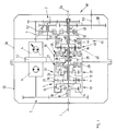
- the single figure shows the structure of a Embodiment of a power split transmission according to the invention.
- a drive shaft 1 drives via a countershaft 2 and a cantilevered and therefore axial play compensating Connection shaft 3 an adjustable hydrostatic adjustment unit 4 on. Furthermore, the drive shaft 1 multiple coupling drive 5 driven.
- the multi-shaft coupling gear 5 is here directly on the Drive shaft 1 arranged.
- the hydrostatic adjustment unit 4 interacts with a hydrostatic constant unit 6.
- the Hydrostat constant unit 6 drives via a countershaft 7 a second input shaft 8 of the coupling gear 5.
- the Coupling gear 5 contains two three-shaft planetary gear sets 9, 10.
- the drive shaft 1 is with a planet carrier 11 of the planetary gear set 9 connected.
- the planetary gear set 9 contains planet gears 12.
- the drive shaft 1 is fixed with a ring gear 13 of the second planetary gear set 10 connected.
- the second planetary gear set 10 contains planet gears 14.
- the second input shaft 8 is fixed to one Sun gear 15 of the second planetary gear set 10 connected.
- a sun gear 16 of the first planetary gear set 9 is on a coupling shaft 17 attached.
- a planet carrier 18 of the second planetary gear set 10 is with a ring gear 19 the planetary gear set 9 and a coupling shaft 20 connected.
- the coupling shafts 17 and 20 are with a second coupling gear 21 connected, which has a planetary gear set 22.
- a sun gear 23 of the planetary gear set 22 is included the sun gear 16 of the first planetary gear set 9 and Planet carrier 18 of the second planetary gear set 10 with a planet gear carrier 24 of the planetary gear set 22 connected via the coupling shaft 20.
- Outer plates 26 of a clutch 27 are attached in a rotationally fixed manner.
- the Outer slats 26 engage between slats 28 which a shaft 29 are rotatably attached.
- a carrier 30 is mounted on the coupling shaft 17 via non-rotatable inner plates 31 between those on the shaft 29 rotatably mounted disks 28 of a clutch 32 intervenes.
- outer plates 34 of a clutch 35 On an intermediate shaft connected to the coupling shaft 20 33 are outer plates 34 of a clutch 35 rotatably assembled.
- the outer fins 34 engage between fins 36, which are rotatably mounted on a shaft 37.
- the coupling and intermediate shaft 20, 33 are in one piece Component manufactured.
- the shaft 29 contains non-rotatable inner plates 38 which reach between the plates 36 of a clutch 39.
- the shaft 29 is fixed with a sun gear 40 fourth planetary gear set 41 connected.
- the fourth planetary gear set 41 has planet gears 42.
- a ring gear 43 of the fourth planetary gear set 41 is via a multi-disc brake 45 connectable with a gear housing 46.
- the shaft 37 carries the planet gears 42 of the fourth planetary gear set 41 and is connected to a shaft 48.
- Outer plates 49 form a clutch K V for forward travel with inner plates 50.
- the outer plates of the clutch K V are rotatably connected to the shaft 48.
- the shaft 48 is also connected via a reversing gear 51 to outer plates 52 of a clutch K R. Both the clutch K R and the clutch K V can transmit the respective torques to an output shaft 53, a PTO clutch (not shown), from which a PTO shaft 54 is driven, being arranged on the output shaft of the power split transmission on the drive shaft 1.
- the clutch K R is shown located relatively far from the output shaft 53.
- the clutch K R like the clutch K V, is arranged next to the drive shaft 1 and, as indicated by the broken line in the figure, is operatively connected to a gearwheel 58 provided on the output shaft 53.
- the gear housing 46 is made in two parts has a facing the input side of the drive shaft 1 front housing part 55 and a rear housing part 56 on.
- a front Plate 57 On the front housing part 55 is a front Plate 57 arranged on which the hydrostatic adjustment unit 4 and the hydrostatic constant unit 6 are attached. These units can be attached via rubber bearings. The The bearings can be lubricated centrally.
- the drive shaft 1, on which the coupling gear 5 is arranged is, carries and centers according to the above arrangement described the four planetary gear sets 9, 10, 22nd and 41.
- the PTO 54 is on the PTO clutch, not shown can be driven directly from the drive shaft 1. There is also a gear wheel of the countershaft 2 for the hydrostatic Power branch attached to the drive shaft 1.
- the hydrostatic adjustment unit 4 is driven in proportion to the speed of an engine, for example an internal combustion engine.
- an engine for example an internal combustion engine.
- the hydrostatic constant unit 6 is accelerated and the ring gear 25 of the planetary gear set 22 is brought to zero speed by summing the speeds of the drive shaft 1 and the second input shaft 8 in the coupling gears 5 and 21. If the rotational speed of the ring gear 25 is zero, the clutch 27 closes.
- the sum of the powers from the hydrostatic and the mechanical branch that is to say the sum of the powers transmitted via the drive shaft 1 and the second input shaft 8 flows via the sun gear 16 Planet carrier 18, the coupling shafts 17, 20 and the ring gear 25 of the planetary gear set 22 and the clutch 27 to the sun gear 40 of the fourth planetary gear set 41.
- the multi-disc brake 45 is closed, so that the ring gear 43 of the fourth planetary gear set 41 stands still.
- the power thus flows via one of the clutches K V or K R to the output shaft 53.
- the further conversion of the transmission ratio of the power split transmission shown is achieved by a further adjustment of the hydrostatic adjustment unit 4.
- the clutch 32 closes and the clutch 27 opens. Then the total power flows through the sun gear 16 of the planetary gear set 9, the coupling shaft 17 and the closed clutch 32.
- the further power flow in this driving range takes place via the sun gear 40 of the fourth planetary gear set 41 and with the brake 45 closed and thus the fixed ring gear 43 either via K V or K R to the output shaft 53.
- the clutch 35 is closed at the synchronous speed of the intermediate shaft 33 and the shaft 37 and then the multi-disc brake 45 is immediately opened.
- the combined power from the mechanical and hydrostatic power branch then flows via the coupling shaft 20 and the intermediate shaft 33 via the clutch 35 and, when the multi-disc brake 45 is open, via the clutch K V or K R to the output shaft 53 of the power split transmission.
- the fourth driving range of the power split transmission is achieved by closing the clutch 39 at Synchronous speed of the clutch 35 and immediately following Opening the clutch 35.
- the total power out the mechanical and hydrostatic power branch flows then over the sun 16 of the first planetary gear set 9 via clutch 32 and clutch 39 and when open Multi-disc brake 45 to the output shaft 53 of the transmission.
- the direction of travel i.e. forward or reverse travel, can be selected in the four driving ranges or driving stages described.
- the vehicle can be reversed at low speeds via the clutches K V and K R.
- the gear ratio currently set remains constant during the reversing process. It is only changed again after reversing via the clutches K V / K R has been completed. As a result, fast reversing shifts can be achieved without interruption of tractive power with good shifting comfort.
Landscapes
- Engineering & Computer Science (AREA)
- General Engineering & Computer Science (AREA)
- Mechanical Engineering (AREA)
- Structure Of Transmissions (AREA)
- Transmission Devices (AREA)
Claims (4)
- Boíte de vitesses à branches de transmission de la puissance, comportant une branche de transmission de la puissance mécanique et une branche de transmission de la puissance hydrostatique,caractérisée en ce que, par l'intermédiaire des embrayages ou des éléments de commande logés dans la boíte intermédiaire, il est possible d'enclencher quatre plages de vitesses, qui, au choix, sont commutées, au moyen de l'embrayage de marche avant (KV) ou à l'aide de l'embrayage de marche arrière (KR), sur l'arbre de sortie (53), en tenant compte du fait que - respectivement dans la même plage de vitesses - la force de traction du véhicule est presque égale en marche avant et en marche arrière.sachant que les deux branches sont disposées dans un carter de boíte de vitesses (46), qu'elles sont entraínées par un arbre d'entrée commun (1) et qu'elles sont raccordées dans un mécanisme de sommation logé dans une boíte intermédiaire (5);sachant que la boíte intermédiaire, comportant plusieurs trains planétaires (9, 10, 22, 41), embrayages et éléments de commande, peut être en liaison d'entraínement avec un arbre de sortie (53);sachant que la boíte intermédiaire est logée sur l'arbre d'entrée etsachant que le dernier train planétaire (41) de la boíte intermédiaire peut être relié à un embrayage pour l'enclenchement de la marche avant (KV) et un embrayage pour l'enclenchement de la marche arrière (KR),
- Boíte de vitesses à branches de transmission de la puissance selon revendication 1, caractérisée en ce que dans l'arbre d'entrée (1) sont prévus des trous d'alimentation en huile de pression des embrayages (27, 32, 35, 39, KV, KR) et des trous d'alimentation en huile lubrifiante de la boíte intermédiaire (5).
- Boíte de vitesses à branches de transmission de la puissance selon les revendications 1 ou 2, caractérisée en ce qu'un arbre de prise de mouvement (54) peut être entraíné directement par l'arbre d'entrée (1).
- Boíte de vitesses à branches de transmission de la puissance selon les revendications de 1 à 3, caractérisée en ce que le carter de la boíte de vitesses (46) est constitué par deux parties, c'est-à-dire une partie antérieure du carter (55), orientée vers le coté entrée de l'arbre d'entrée (1), et une partie postérieure du carter (56).
Applications Claiming Priority (3)
| Application Number | Priority Date | Filing Date | Title |
|---|---|---|---|
| DE19522833 | 1995-06-23 | ||
| DE19522833A DE19522833A1 (de) | 1995-06-23 | 1995-06-23 | Leistungsverzweigungsgetriebe |
| PCT/EP1996/002590 WO1997001049A1 (fr) | 1995-06-23 | 1996-06-15 | Transmission a derivation de puissance hydrostatique--mecanique |
Publications (2)
| Publication Number | Publication Date |
|---|---|
| EP0834027A1 EP0834027A1 (fr) | 1998-04-08 |
| EP0834027B1 true EP0834027B1 (fr) | 1999-03-24 |
Family
ID=7765084
Family Applications (1)
| Application Number | Title | Priority Date | Filing Date |
|---|---|---|---|
| EP96922813A Expired - Lifetime EP0834027B1 (fr) | 1995-06-23 | 1996-06-15 | Transmission a derivation de puissance hydrostatique--mecanique |
Country Status (5)
| Country | Link |
|---|---|
| US (1) | US6042496A (fr) |
| EP (1) | EP0834027B1 (fr) |
| AT (1) | ATE178126T1 (fr) |
| DE (2) | DE19522833A1 (fr) |
| WO (1) | WO1997001049A1 (fr) |
Cited By (11)
| Publication number | Priority date | Publication date | Assignee | Title |
|---|---|---|---|---|
| DE10128076A1 (de) * | 2001-06-09 | 2002-12-12 | Zahnradfabrik Friedrichshafen | Leistungsverzweigungsgetriebe |
| DE10243206A1 (de) * | 2002-09-18 | 2004-03-25 | Zf Friedrichshafen Ag | Lastschaltgetriebe |
| DE10304917A1 (de) * | 2003-02-07 | 2004-08-19 | Zf Friedrichshafen Ag | Stufenloses Getriebe |
| DE10322232A1 (de) * | 2003-05-17 | 2004-12-02 | Zf Friedrichshafen Ag | Leistungsverzweigungsgetriebe |
| DE102007017176A1 (de) | 2007-04-12 | 2008-10-16 | Zf Friedrichshafen Ag | Hydrostatisch-mechanisches Leistungsverzweigungsgetriebe |
| DE102007035307A1 (de) | 2007-07-27 | 2009-01-29 | Zf Friedrichshafen Ag | Vorrichtung zur Drehrichtungsumkehr für ein stufenloses hydrostatisch-mechanisches Leistungsverzweigungsgetriebe |
| DE102007000619A1 (de) | 2007-11-05 | 2009-05-07 | Zf Friedrichshafen Ag | Hydrostatisch-mechanisches Leistungsverzweigungsgetriebe |
| DE10123105B4 (de) * | 2001-05-12 | 2010-08-26 | Zf Friedrichshafen Ag | Leistungsverzweigungsgetriebe |
| DE10332216B4 (de) * | 2003-07-16 | 2012-02-02 | Zf Friedrichshafen Ag | Hydrostatisch-mechanisches Leistungsverzweigungsgetriebe |
| DE102019216936A1 (de) * | 2019-11-04 | 2021-05-06 | Zf Friedrichshafen Ag | Leistungsverzweigungsgetriebe und Arbeitsmaschine |
| DE102019218937A1 (de) * | 2019-12-05 | 2021-06-10 | Zf Friedrichshafen Ag | Leistungsverzweigungsgetriebe und Arbeitsmaschine |
Families Citing this family (45)
| Publication number | Priority date | Publication date | Assignee | Title |
|---|---|---|---|---|
| US5890981A (en) * | 1996-11-25 | 1999-04-06 | Caterpillar Inc. | Hydromechanical transmission having three planetaries and five members |
| DE19830950A1 (de) * | 1998-07-10 | 2000-01-13 | Zahnradfabrik Friedrichshafen | Verfahren und Vorrichtung zur Betätigung einer Kraftfahrzeug-Kupplungsvorrichtung |
| DE19830951A1 (de) | 1998-07-10 | 2000-01-13 | Zahnradfabrik Friedrichshafen | Lamellenkupplung in einem leistungsverzweigten Getriebe |
| DE19830953A1 (de) | 1998-07-10 | 2000-03-30 | Zahnradfabrik Friedrichshafen | Verfahren und Vorrichtung zur Steuerung eines Kraftfahrzeug-Antriebsstranges |
| DE19932806A1 (de) | 1999-07-14 | 2001-01-18 | Zahnradfabrik Friedrichshafen | Leistungsverzweigungsgetriebe |
| DE19933822A1 (de) * | 1999-07-20 | 2001-02-01 | Zahnradfabrik Friedrichshafen | Leistungsverzweigungsgetriebe |
| US6440026B1 (en) | 2000-09-26 | 2002-08-27 | Deere & Company | Hydro-mechanical transmission |
| US6565471B2 (en) * | 2000-12-19 | 2003-05-20 | Case Corporation | Continuously variable hydro-mechanical transmission |
| DE10122823B4 (de) * | 2001-05-11 | 2011-03-03 | Zf Friedrichshafen Ag | Leistungsverzweigungsgetriebe |
| US6609368B2 (en) | 2001-06-04 | 2003-08-26 | Caterpillar S.A.R.L. | Automatic downshift and override control for a transmission |
| DE102004001929A1 (de) | 2004-01-14 | 2005-08-04 | Zf Friedrichshafen Ag | Hydrostatisch-mechanisches Leistungsverzweigungsgetriebe |
| US7241242B2 (en) * | 2004-10-28 | 2007-07-10 | General Motors Corporation | Two-mode compound-split hydraulic continuously variable transmission |
| JP4467501B2 (ja) * | 2005-09-30 | 2010-05-26 | 株式会社クボタ | トラクタの変速伝動装置 |
| DE102006025348A1 (de) * | 2006-05-31 | 2007-12-06 | Sauer-Danfoss Gmbh & Co Ohg | Hydrostatisch-mechanisches Getriebe |
| KR101020410B1 (ko) * | 2007-03-05 | 2011-03-08 | 가부시끼 가이샤 구보다 | 변속 동력 전달 장치 |
| US8308597B2 (en) * | 2007-09-20 | 2012-11-13 | Kubota Corporation | Speed change transmission system |
| DE102008001612B4 (de) | 2008-05-07 | 2020-10-29 | Zf Friedrichshafen Ag | Stufenloses Leistungsverzweigungsgetriebe |
| AU2014229074B2 (en) * | 2013-03-15 | 2017-05-25 | Allison Transmission, Inc. | Split power infinitely variable transmission architecture |
| EP2955418B1 (fr) * | 2014-06-13 | 2019-02-20 | Perkins Engines Company Limited | Transmission assistée par variateur |
| ES2810400T3 (es) * | 2015-12-10 | 2021-03-08 | Edi Bondioli | Sistema que comprende un remolque mezclador, para mezclar y distribuir forraje, y una unidad mecánica de transmisión de potencia para accionar el remolque mezclador |
| US10384714B2 (en) * | 2016-12-16 | 2019-08-20 | Allison Transmission, Inc. | Direct drive pivot and pivot lockup of a transmission system and method thereof |
| DE102017200240A1 (de) | 2017-01-10 | 2018-07-12 | Zf Friedrichshafen Ag | Leistungsverzweigungsgetriebe |
| DE102017219999A1 (de) | 2017-11-10 | 2019-05-16 | Zf Friedrichshafen Ag | Stufenloses Leistungsverzweigungsgetriebe mit wenigstens vier Fahrbereichen |
| DE102017220000A1 (de) | 2017-11-10 | 2019-05-16 | Zf Friedrichshafen Ag | Stufenloses Leistungsverzweigungsgetriebe mit zwei Fahrbereichen |
| DE102019219360A1 (de) * | 2019-12-11 | 2021-06-17 | Zf Friedrichshafen Ag | Stufenloses Leistungsverzweigungsgetriebe |
| DE102019219359A1 (de) * | 2019-12-11 | 2021-06-17 | Zf Friedrichshafen Ag | Leistungsverzweigtes stufenloses Getriebe |
| DE102019219350A1 (de) * | 2019-12-11 | 2021-06-17 | Zf Friedrichshafen Ag | Leistungsverzweigtes stufenloses Getriebe |
| DE102019219344A1 (de) * | 2019-12-11 | 2021-06-17 | Zf Friedrichshafen Ag | Leistungsverzweigtes stufenloses Getriebe |
| DE102020201004B3 (de) * | 2020-01-28 | 2021-07-01 | Zf Friedrichshafen Ag | Leistungsverzweigtes stufenloses Getriebe |
| DE102020200999B3 (de) | 2020-01-28 | 2021-07-29 | Zf Friedrichshafen Ag | Leistungsverzweigtes stufenloses Getriebe |
| DE102020201692B3 (de) | 2020-02-11 | 2021-07-22 | Zf Friedrichshafen Ag | Leistungsverzweigtes stufenloses Getriebe |
| DE102020201690B3 (de) | 2020-02-11 | 2021-07-29 | Zf Friedrichshafen Ag | Leistungsverzweigtes stufenloses Getriebe |
| DE102020201775B3 (de) * | 2020-02-13 | 2021-02-04 | Zf Friedrichshafen Ag | Leistungsverzweigtes stufenloses Getriebe |
| DE102020202000B4 (de) | 2020-02-18 | 2022-08-18 | Zf Friedrichshafen Ag | Leistungsverzweigtes stufenloses Getriebe |
| DE102020202008B4 (de) | 2020-02-18 | 2021-09-30 | Zf Friedrichshafen Ag | Leistungsverzweigtes stufenloses Getriebe |
| DE102020202003B3 (de) | 2020-02-18 | 2021-07-29 | Zf Friedrichshafen Ag | Leistungsverzweigtes stufenloses Getriebe |
| DE102020202415B4 (de) | 2020-02-25 | 2022-06-15 | Zf Friedrichshafen Ag | Leistungsverzweigtes stufenloses Getriebe |
| DE102020202419B3 (de) * | 2020-02-25 | 2021-06-17 | Zf Friedrichshafen Ag | Leistungsverzweigtes stufenloses Getriebe |
| DE102020202413B3 (de) * | 2020-02-25 | 2021-05-12 | Zf Friedrichshafen Ag | Leistungsverzweigtes stufenloses Getriebe |
| DE102020202417B3 (de) * | 2020-02-25 | 2021-06-17 | Zf Friedrichshafen Ag | Leistungsverzweigtes stufenloses Getriebe |
| DE102020202416B3 (de) | 2020-02-25 | 2021-07-22 | Zf Friedrichshafen Ag | Leistungsverzweigtes stufenloses Getriebe |
| DE102021200739A1 (de) | 2021-01-27 | 2022-07-28 | Zf Friedrichshafen Ag | Leistungsverzweigtes stufenloses Getriebe |
| DE102022207434A1 (de) * | 2022-07-21 | 2024-02-01 | Zf Friedrichshafen Ag | Stufenloses Leistungsverzweigungsgetriebe |
| DE102023200926B4 (de) | 2023-02-06 | 2025-04-24 | Zf Friedrichshafen Ag | Verfahren und Steuerungsvorrichtung zum Steuern einer Antriebseinrichtung für ein Fahrzeug |
| DE102023202275A1 (de) | 2023-03-14 | 2024-09-19 | Zf Friedrichshafen Ag | Antriebseinrichtung für ein Fahrzeug |
Family Cites Families (26)
| Publication number | Priority date | Publication date | Assignee | Title |
|---|---|---|---|---|
| US3777593A (en) * | 1971-11-22 | 1973-12-11 | Gen Motors Corp | Multi-range coaxial hydromechanical transmission |
| US3736813A (en) * | 1971-12-27 | 1973-06-05 | Deere & Co | Combined hydrostatic and mechanical transmission |
| US3810519A (en) * | 1972-03-01 | 1974-05-14 | Int Harvester Co | Vehicle transmission assembly |
| DE2351834A1 (de) * | 1973-10-16 | 1975-04-24 | Zahnradfabrik Friedrichshafen | Fahrzeugachse mit einem ausserhalb des achsgehaeuses quer zur fahrtrichtung angeordneten antriebsmotor |
| US3990327A (en) * | 1975-01-08 | 1976-11-09 | Ford Motor Company | Multiple range hydrostatic transmission mechanism |
| US4134310A (en) * | 1977-04-15 | 1979-01-16 | Orshansky Transmission Corporation | Hydromechanical transmission with hydrodynamic drive |
| DE2757191C2 (de) * | 1977-12-22 | 1983-01-13 | Zahnradfabrik Friedrichshafen Ag, 7990 Friedrichshafen | Stufenlos einstellbares hydrostatisch-mechanisches Verbundgetriebe |
| DE2757300C2 (de) * | 1977-12-22 | 1982-08-12 | Zahnradfabrik Friedrichshafen Ag, 7990 Friedrichshafen | Leistungsverzweigtes hydrostatisch-mechanisches Verbundgetriebe |
| US4258585A (en) * | 1978-05-02 | 1981-03-31 | Orshansky Transmission Corporation | Four-range hydromechanical transmission with hydrostatic steering module |
| DD144347A1 (de) * | 1979-08-21 | 1980-10-15 | Siegfried Scholz | Verfahren zur abschaltung eines stirnrad-wendegetriebes zur vermeidung von unfaellen bei landwirtschaftlichen arbeitsmaschinen |
| DE2943281A1 (de) * | 1979-10-26 | 1981-05-07 | Zahnradfabrik Friedrichshafen Ag, 7990 Friedrichshafen | Hydrostatisch-mechanischer antrieb fuer selbstfahrende arbeitsmaschinen |
| CA1184789A (fr) * | 1981-02-21 | 1985-04-02 | Julian Parraga Garcia | Transmission hydromecanique a grand rendement |
| US5328418A (en) * | 1985-09-18 | 1994-07-12 | Michael Meyerle | Stepless hydromechanical mechanism with multiple power-transmission paths, more particularly for motor vehicles |
| US4856368A (en) * | 1987-06-26 | 1989-08-15 | Kanzaki Kokyukoki Mfg. Co. Ltd. | HST (hydrostatic transmission) containing axle drive apparatus |
| US5159855A (en) * | 1989-07-14 | 1992-11-03 | Zahnradfabrik Friedrichshafen Ag | Continuously variable driving unit of a motor vehicle |
| JP2517464Y2 (ja) * | 1990-05-28 | 1996-11-20 | 株式会社神崎高級工機製作所 | 作業車両用のトランスミツシヨン装置 |
| DE4021643A1 (de) * | 1990-07-06 | 1992-01-16 | Claas Ohg | Hydrostatisch-leistungsverzweigtes mehrgang-lastschaltgetriebe |
| DE4030050A1 (de) * | 1990-09-20 | 1992-03-26 | Mannesmann Ag | Hydrostatisch mechanisches lastschaltgetriebe |
| DE4115624C2 (de) * | 1991-05-14 | 1995-06-22 | Deere & Co | Hydrostatisch-mechanisches Leistungsverzweigungsgetriebe |
| US5125291A (en) * | 1991-07-15 | 1992-06-30 | Honda Giken Kogyo Kabushiki Kaisha | Transmission with hydrostatic power unit |
| DE4243018A1 (de) * | 1992-12-18 | 1994-06-23 | Zahnradfabrik Friedrichshafen | Hydrostatisch-mechanisches Leistungsverzweigungsgetriebe |
| US5683322A (en) * | 1993-04-21 | 1997-11-04 | Meyerle; Michael | Continuous hydrostatic-mechanical branch power split transmission particularly for power vehicles |
| JP3659992B2 (ja) * | 1994-08-31 | 2005-06-15 | 本田技研工業株式会社 | 油圧・機械式伝動装置 |
| DE19506062A1 (de) * | 1995-02-22 | 1996-09-05 | Deere & Co | Hydrostatisch-mechanisches Leistungsverzweigungsgetriebe |
| US5667452A (en) * | 1995-04-06 | 1997-09-16 | Caterpillar Inc. | Split torque transmission |
| JP2981980B2 (ja) * | 1996-02-22 | 1999-11-22 | 本田技研工業株式会社 | 油圧・機械式伝動装置 |
-
1995
- 1995-06-23 DE DE19522833A patent/DE19522833A1/de not_active Withdrawn
-
1996
- 1996-06-15 DE DE59601507T patent/DE59601507D1/de not_active Expired - Lifetime
- 1996-06-15 EP EP96922813A patent/EP0834027B1/fr not_active Expired - Lifetime
- 1996-06-15 US US08/952,605 patent/US6042496A/en not_active Expired - Lifetime
- 1996-06-15 WO PCT/EP1996/002590 patent/WO1997001049A1/fr not_active Ceased
- 1996-06-15 AT AT96922813T patent/ATE178126T1/de not_active IP Right Cessation
Cited By (13)
| Publication number | Priority date | Publication date | Assignee | Title |
|---|---|---|---|---|
| DE10123105B4 (de) * | 2001-05-12 | 2010-08-26 | Zf Friedrichshafen Ag | Leistungsverzweigungsgetriebe |
| DE10128076A1 (de) * | 2001-06-09 | 2002-12-12 | Zahnradfabrik Friedrichshafen | Leistungsverzweigungsgetriebe |
| DE10243206A1 (de) * | 2002-09-18 | 2004-03-25 | Zf Friedrichshafen Ag | Lastschaltgetriebe |
| DE10304917A1 (de) * | 2003-02-07 | 2004-08-19 | Zf Friedrichshafen Ag | Stufenloses Getriebe |
| DE10304917B4 (de) * | 2003-02-07 | 2017-05-11 | Zf Friedrichshafen Ag | Stufenloses Getriebe |
| DE10322232B4 (de) * | 2003-05-17 | 2012-02-02 | Zf Friedrichshafen Ag | Leistungsverzweigungsgetriebe |
| DE10322232A1 (de) * | 2003-05-17 | 2004-12-02 | Zf Friedrichshafen Ag | Leistungsverzweigungsgetriebe |
| DE10332216B4 (de) * | 2003-07-16 | 2012-02-02 | Zf Friedrichshafen Ag | Hydrostatisch-mechanisches Leistungsverzweigungsgetriebe |
| DE102007017176A1 (de) | 2007-04-12 | 2008-10-16 | Zf Friedrichshafen Ag | Hydrostatisch-mechanisches Leistungsverzweigungsgetriebe |
| DE102007035307A1 (de) | 2007-07-27 | 2009-01-29 | Zf Friedrichshafen Ag | Vorrichtung zur Drehrichtungsumkehr für ein stufenloses hydrostatisch-mechanisches Leistungsverzweigungsgetriebe |
| DE102007000619A1 (de) | 2007-11-05 | 2009-05-07 | Zf Friedrichshafen Ag | Hydrostatisch-mechanisches Leistungsverzweigungsgetriebe |
| DE102019216936A1 (de) * | 2019-11-04 | 2021-05-06 | Zf Friedrichshafen Ag | Leistungsverzweigungsgetriebe und Arbeitsmaschine |
| DE102019218937A1 (de) * | 2019-12-05 | 2021-06-10 | Zf Friedrichshafen Ag | Leistungsverzweigungsgetriebe und Arbeitsmaschine |
Also Published As
| Publication number | Publication date |
|---|---|
| DE59601507D1 (de) | 1999-04-29 |
| DE19522833A1 (de) | 1997-01-02 |
| ATE178126T1 (de) | 1999-04-15 |
| WO1997001049A1 (fr) | 1997-01-09 |
| EP0834027A1 (fr) | 1998-04-08 |
| US6042496A (en) | 2000-03-28 |
Similar Documents
| Publication | Publication Date | Title |
|---|---|---|
| EP0834027A1 (fr) | Transmission a derivation de puissance hydrostatique--mecanique | |
| EP1626206B1 (fr) | Transmission à division de puissance pour véhicules automobiles | |
| EP0408616B1 (fr) | Boite de vitesses hydrostatique-mecanique a derivation de puissance | |
| EP1910711B1 (fr) | Boite a derivation de puissance comportant plusieurs plages de transmission a reglage variable | |
| EP0081696B1 (fr) | Transmission hydromécanique avec division de puissance à l'entrée | |
| EP0481014B1 (fr) | Boite de vitesse a engrenages a etages multiples | |
| DE202015102282U1 (de) | Hydrostatisch-mechanisches Leistungsverzweigungsgetriebe | |
| DE2937143A1 (de) | Schaltgetriebe fuer landwirtschaftliche zugmaschinen u.ae. fahrzeuge | |
| WO2009127324A2 (fr) | Agencement d'essieu moteur d'un véhicule avec boîte de transfert | |
| WO1987006316A1 (fr) | Transmission continue a ramification, en particulier pour vehicules a moteur | |
| EP0939866A1 (fr) | Transmission a reglage continu a branchement de puissance | |
| DE60316082T2 (de) | Getriebe | |
| DE10261991B4 (de) | Geschwindigkeits-Wechselgetriebe | |
| EP0141952B1 (fr) | Transmission hydrostatique-mécanique | |
| EP0818643B1 (fr) | Transmission hydromécanique à division de puissance | |
| DE19944792A1 (de) | Stufenloses Getriebe, insbesondere mit Leistungsverzweigung | |
| EP0291525B1 (fr) | Mecanisme de roulement et de direction progressif pour vehicules a chenilles | |
| DE102004001929A1 (de) | Hydrostatisch-mechanisches Leistungsverzweigungsgetriebe | |
| DE3910410A1 (de) | Hydrostatisch mechanisches leistungsverzweigungsgetriebe | |
| DE102019112157A1 (de) | Zapfwellengetriebeanordnung | |
| EP3961064B1 (fr) | Système de transmission et véhicule tracteur agricole | |
| EP1231413A2 (fr) | Transmission synchronisée | |
| DE19510914C2 (de) | Hydromechanisches Antriebsaggregat | |
| DE4042697C2 (de) | Stufenloses hydrostatisch-mechanisches Leistungsverzweigungsgetriebe, insbesondere für Kraftfahrzeuge | |
| DE19905447A1 (de) | Stufenloses Getriebe mit Leistungsverzweigung |
Legal Events
| Date | Code | Title | Description |
|---|---|---|---|
| PUAI | Public reference made under article 153(3) epc to a published international application that has entered the european phase |
Free format text: ORIGINAL CODE: 0009012 |
|
| AK | Designated contracting states |
Kind code of ref document: A1 Designated state(s): AT DE FI FR GB IT |
|
| 17P | Request for examination filed |
Effective date: 19970918 |
|
| 17Q | First examination report despatched |
Effective date: 19980417 |
|
| GRAG | Despatch of communication of intention to grant |
Free format text: ORIGINAL CODE: EPIDOS AGRA |
|
| GRAG | Despatch of communication of intention to grant |
Free format text: ORIGINAL CODE: EPIDOS AGRA |
|
| GRAH | Despatch of communication of intention to grant a patent |
Free format text: ORIGINAL CODE: EPIDOS IGRA |
|
| GRAH | Despatch of communication of intention to grant a patent |
Free format text: ORIGINAL CODE: EPIDOS IGRA |
|
| RAP1 | Party data changed (applicant data changed or rights of an application transferred) |
Owner name: DEERE & COMPANY Owner name: ZF FRIEDRICHSHAFEN AG |
|
| GRAA | (expected) grant |
Free format text: ORIGINAL CODE: 0009210 |
|
| ITF | It: translation for a ep patent filed | ||
| AK | Designated contracting states |
Kind code of ref document: B1 Designated state(s): AT DE FI FR GB IT |
|
| REF | Corresponds to: |
Ref document number: 178126 Country of ref document: AT Date of ref document: 19990415 Kind code of ref document: T |
|
| REF | Corresponds to: |
Ref document number: 59601507 Country of ref document: DE Date of ref document: 19990429 |
|
| GBT | Gb: translation of ep patent filed (gb section 77(6)(a)/1977) |
Effective date: 19990408 |
|
| ET | Fr: translation filed | ||
| PLBE | No opposition filed within time limit |
Free format text: ORIGINAL CODE: 0009261 |
|
| STAA | Information on the status of an ep patent application or granted ep patent |
Free format text: STATUS: NO OPPOSITION FILED WITHIN TIME LIMIT |
|
| 26N | No opposition filed | ||
| REG | Reference to a national code |
Ref country code: GB Ref legal event code: IF02 |
|
| PGFP | Annual fee paid to national office [announced via postgrant information from national office to epo] |
Ref country code: GB Payment date: 20020527 Year of fee payment: 7 |
|
| PGFP | Annual fee paid to national office [announced via postgrant information from national office to epo] |
Ref country code: AT Payment date: 20020618 Year of fee payment: 7 |
|
| PGFP | Annual fee paid to national office [announced via postgrant information from national office to epo] |
Ref country code: FI Payment date: 20020619 Year of fee payment: 7 |
|
| PG25 | Lapsed in a contracting state [announced via postgrant information from national office to epo] |
Ref country code: GB Free format text: LAPSE BECAUSE OF NON-PAYMENT OF DUE FEES Effective date: 20030615 Ref country code: FI Free format text: LAPSE BECAUSE OF NON-PAYMENT OF DUE FEES Effective date: 20030615 Ref country code: AT Free format text: LAPSE BECAUSE OF NON-PAYMENT OF DUE FEES Effective date: 20030615 |
|
| GBPC | Gb: european patent ceased through non-payment of renewal fee |
Effective date: 20030615 |
|
| PGFP | Annual fee paid to national office [announced via postgrant information from national office to epo] |
Ref country code: IT Payment date: 20060630 Year of fee payment: 11 |
|
| PG25 | Lapsed in a contracting state [announced via postgrant information from national office to epo] |
Ref country code: IT Free format text: LAPSE BECAUSE OF NON-PAYMENT OF DUE FEES Effective date: 20070615 |
|
| REG | Reference to a national code |
Ref country code: FR Ref legal event code: PLFP Year of fee payment: 20 |
|
| PGFP | Annual fee paid to national office [announced via postgrant information from national office to epo] |
Ref country code: DE Payment date: 20150609 Year of fee payment: 20 |
|
| PGFP | Annual fee paid to national office [announced via postgrant information from national office to epo] |
Ref country code: FR Payment date: 20150608 Year of fee payment: 20 |
|
| REG | Reference to a national code |
Ref country code: DE Ref legal event code: R071 Ref document number: 59601507 Country of ref document: DE |