EP0481123A2 - Moteur à piston pour un véhicule - Google Patents
Moteur à piston pour un véhicule Download PDFInfo
- Publication number
- EP0481123A2 EP0481123A2 EP90122251A EP90122251A EP0481123A2 EP 0481123 A2 EP0481123 A2 EP 0481123A2 EP 90122251 A EP90122251 A EP 90122251A EP 90122251 A EP90122251 A EP 90122251A EP 0481123 A2 EP0481123 A2 EP 0481123A2
- Authority
- EP
- European Patent Office
- Prior art keywords
- alternator
- engine
- crankshaft
- driven
- housing
- Prior art date
- Legal status (The legal status is an assumption and is not a legal conclusion. Google has not performed a legal analysis and makes no representation as to the accuracy of the status listed.)
- Withdrawn
Links
Images

Classifications
-
- F—MECHANICAL ENGINEERING; LIGHTING; HEATING; WEAPONS; BLASTING
- F02—COMBUSTION ENGINES; HOT-GAS OR COMBUSTION-PRODUCT ENGINE PLANTS
- F02B—INTERNAL-COMBUSTION PISTON ENGINES; COMBUSTION ENGINES IN GENERAL
- F02B67/00—Engines characterised by the arrangement of auxiliary apparatus not being otherwise provided for, e.g. the apparatus having different functions; Driving auxiliary apparatus from engines, not otherwise provided for
- F02B67/04—Engines characterised by the arrangement of auxiliary apparatus not being otherwise provided for, e.g. the apparatus having different functions; Driving auxiliary apparatus from engines, not otherwise provided for of mechanically-driven auxiliary apparatus
- F02B67/06—Engines characterised by the arrangement of auxiliary apparatus not being otherwise provided for, e.g. the apparatus having different functions; Driving auxiliary apparatus from engines, not otherwise provided for of mechanically-driven auxiliary apparatus driven by means of chains, belts, or like endless members
-
- F—MECHANICAL ENGINEERING; LIGHTING; HEATING; WEAPONS; BLASTING
- F02—COMBUSTION ENGINES; HOT-GAS OR COMBUSTION-PRODUCT ENGINE PLANTS
- F02B—INTERNAL-COMBUSTION PISTON ENGINES; COMBUSTION ENGINES IN GENERAL
- F02B75/00—Other engines
- F02B75/16—Engines characterised by number of cylinders, e.g. single-cylinder engines
- F02B75/18—Multi-cylinder engines
- F02B75/22—Multi-cylinder engines with cylinders in V, fan, or star arrangement
-
- F—MECHANICAL ENGINEERING; LIGHTING; HEATING; WEAPONS; BLASTING
- F02—COMBUSTION ENGINES; HOT-GAS OR COMBUSTION-PRODUCT ENGINE PLANTS
- F02B—INTERNAL-COMBUSTION PISTON ENGINES; COMBUSTION ENGINES IN GENERAL
- F02B75/00—Other engines
- F02B75/16—Engines characterised by number of cylinders, e.g. single-cylinder engines
- F02B75/18—Multi-cylinder engines
- F02B2075/1804—Number of cylinders
- F02B2075/1848—Number of cylinders twelve
-
- F—MECHANICAL ENGINEERING; LIGHTING; HEATING; WEAPONS; BLASTING
- F02—COMBUSTION ENGINES; HOT-GAS OR COMBUSTION-PRODUCT ENGINE PLANTS
- F02B—INTERNAL-COMBUSTION PISTON ENGINES; COMBUSTION ENGINES IN GENERAL
- F02B2275/00—Other engines, components or details, not provided for in other groups of this subclass
- F02B2275/06—Endless member is a belt
-
- F—MECHANICAL ENGINEERING; LIGHTING; HEATING; WEAPONS; BLASTING
- F02—COMBUSTION ENGINES; HOT-GAS OR COMBUSTION-PRODUCT ENGINE PLANTS
- F02B—INTERNAL-COMBUSTION PISTON ENGINES; COMBUSTION ENGINES IN GENERAL
- F02B2275/00—Other engines, components or details, not provided for in other groups of this subclass
- F02B2275/18—DOHC [Double overhead camshaft]
Definitions
- the invention relates to a reciprocating piston engine for a motor vehicle with two rows of cylinders arranged in a V-shape according to the preamble of claim 1.
- Such a reciprocating piston engine is known from DE-Z Sonderbuch ATZ, Automobiltechnische Zeitschrift, 71st year, No. 9/12/1969 and 73rd year No. 5/1971.
- An output shaft driven by the crankshaft for the clutch runs - seen in the vertical direction of the vehicle - below the crankshaft, parallel to it. It is driven by the crankshaft via a gear transmission which is arranged in a central plane between the two crankshaft ends.
- the output shaft also drives the gear pumps and the oil pumps located in the engine crankcase.
- An alternator which is screwed to the top of the engine housing, is used to power the engine.
- the alternator designed as a three-phase generator on the engine housing in such a way that a symmetrical weight distribution of the engine can be achieved with respect to the longitudinal axis of the engine, that the center of gravity of the engine is as low as possible and that the alternator is driven correctly.
- the characteristic features of claim 1 serve to solve this problem. If the alternator is located in the V center, it is arranged symmetrically to the longitudinal axis and contributes to an even weight distribution of the engine. Since it is adapted according to claim 2 with a narrow radial distance to the outer walls of the V-neck, its center of gravity can have a minimal geodetic height. As a result of its position vertically above the crankshaft, it can be driven directly by it using simple constructional means.
- the alternator is driven by an intermediate shaft designed as a resilient torsion bar, which is driven by it lying above the crankshaft.
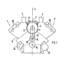
- a reciprocating piston engine has two V-shaped cylinder rows 1 and 2, each with 6 cylinders.
- a suction port 3 leads to each cylinder.
- a three-phase alternator 6 is arranged in the V-section 4 in the V-center 5. Its housing 7 is screwed with tabs 8 to the right cylinder row 1 and left cylinder row 2, as seen in the direction of travel A.
- the outer walls of the motor housing 9 which delimit the V-neck 4 are shaped cylindrically in accordance with the cylindrical housing 7 of the alternator 6. They surround it with a small radial distance s.
- One end face 10 of the housing 7 of the alternator 6 is flush with the front end face 11 of the motor housing 9, which is opposite a transverse wall 12 of the vehicle body at a short distance.
- a belt drive 13 is arranged on the end faces 10 and 11 from an intermediate shaft 14 to the shaft 6 'of the alternator 6.
- the intermediate shaft 14 is non-rotatably in an output shaft 15 for clutch 16.
- the output shaft 16 is driven in the central plane 17 by the crankshaft 18 with a gear set 19.
- the central plane 17 lies approximately centrally between the front end 20 and the rear end 21 of the crankshaft 18.
- the translation from the crankshaft 18 to the output shaft 15 and from the intermediate shaft 14 to the shaft 6 'of the alternator 6 is in each case approximately 1: 1, so that the alternator 6 rotates at approximately the same speed as the crankshaft 18. If such a piston engine is used as a racing engine , the maximum crankshaft speed is approx. 14,000 rpm.
- the intermediate shaft 14 is designed as a resilient torsion bar so that shocks in the power transmission are reduced. In addition, the vibrations are weakened by the belt drive 13.
- the right pump set 24, which is arranged on one long side of the motor housing, and the left pump set 25, which is arranged on the other long side of the motor, are driven via the output shaft 15 with left wheel sets 22 and right wheel sets.
- the pump sets 24 and 25 each consist of a water pump, an oil suction pump and an oil pressure pump.
Landscapes
- Engineering & Computer Science (AREA)
- Chemical & Material Sciences (AREA)
- Combustion & Propulsion (AREA)
- Mechanical Engineering (AREA)
- General Engineering & Computer Science (AREA)
- Connection Of Motors, Electrical Generators, Mechanical Devices, And The Like (AREA)
- Control Of Vehicle Engines Or Engines For Specific Uses (AREA)
Applications Claiming Priority (2)
| Application Number | Priority Date | Filing Date | Title |
|---|---|---|---|
| DE4032591 | 1990-10-13 | ||
| DE4032591A DE4032591A1 (de) | 1990-10-13 | 1990-10-13 | Hubkolbenmotor fuer ein kraftfahrzeug |
Publications (2)
| Publication Number | Publication Date |
|---|---|
| EP0481123A2 true EP0481123A2 (fr) | 1992-04-22 |
| EP0481123A3 EP0481123A3 (en) | 1992-06-10 |
Family
ID=6416254
Family Applications (1)
| Application Number | Title | Priority Date | Filing Date |
|---|---|---|---|
| EP19900122251 Withdrawn EP0481123A3 (en) | 1990-10-13 | 1990-11-22 | Piston engine for a vehicle |
Country Status (4)
| Country | Link |
|---|---|
| US (1) | US5094203A (fr) |
| EP (1) | EP0481123A3 (fr) |
| JP (1) | JPH04234532A (fr) |
| DE (1) | DE4032591A1 (fr) |
Cited By (2)
| Publication number | Priority date | Publication date | Assignee | Title |
|---|---|---|---|---|
| DE19840658A1 (de) * | 1998-09-05 | 2000-03-09 | Volkswagen Ag | Brennkraftmaschine mit wenigstens zwei V-förmig zueinander angeordneten Zylinderreihen |
| WO2000017003A1 (fr) * | 1998-09-21 | 2000-03-30 | Volkswagen Aktiengesellschaft | Configuration de montage d'un groupe motopropulseur d'un vehicule, comprenant un moteur a combustion et une transmission |
Families Citing this family (3)
| Publication number | Priority date | Publication date | Assignee | Title |
|---|---|---|---|---|
| DE19824006A1 (de) * | 1998-05-29 | 1999-12-02 | Deutz Ag | Ölpumpe und Kühlflüssigkeitspumpe einer Brennkraftmaschine |
| DE19910271B4 (de) * | 1999-03-08 | 2014-04-03 | Volkswagen Ag | Brennkraftmaschine |
| DE102004031281B4 (de) * | 2004-06-29 | 2016-09-15 | Man Truck & Bus Ag | Vorrichtung zum Rückführen von Kurbelgehäuseentlüftungsgasen in den Verbrennungsraum einer aufgeladenen Brennkraftmaschine |
Family Cites Families (9)
| Publication number | Priority date | Publication date | Assignee | Title |
|---|---|---|---|---|
| US1173105A (en) * | 1915-01-21 | 1916-02-22 | Hudson Motor Car Co | Internal-combustion engine. |
| US1424928A (en) * | 1921-05-14 | 1922-08-08 | Charles S Mcclelland | Pump |
| US2182290A (en) * | 1938-03-02 | 1939-12-05 | Clyde E Everhart | Railroad switch frog and assembly |
| GB1129147A (en) * | 1964-10-21 | 1968-10-02 | Hedemora Verkst Er Ab | Improvements in or relating to multiple cylinder piston engines |
| AT285246B (de) * | 1966-06-23 | 1970-10-27 | H C Hans Dipl Ing Dr Dr List | Flüssigkeitsgekühlte Brennkrafmaschine mit in V-Form angeordneten Zylindern |
| US3498272A (en) * | 1968-02-01 | 1970-03-03 | Eaton Yale & Towne | Engine accessory drive |
| US4480600A (en) * | 1982-05-24 | 1984-11-06 | General Motors Corporation | Compact odd cylinder V-type engine |
| US4793300A (en) * | 1985-10-21 | 1988-12-27 | Honda Giken Kogyo Kabushiki Kogyo | Accessory attachment structure for a V-shaped engine |
| JPS6436930A (en) * | 1987-07-31 | 1989-02-07 | Fuji Heavy Ind Ltd | Accessories driving gear for engine |
-
1990
- 1990-10-13 DE DE4032591A patent/DE4032591A1/de not_active Withdrawn
- 1990-11-22 EP EP19900122251 patent/EP0481123A3/de not_active Withdrawn
-
1991
- 1991-03-13 US US07/668,930 patent/US5094203A/en not_active Expired - Fee Related
- 1991-08-09 JP JP3200647A patent/JPH04234532A/ja not_active Withdrawn
Cited By (3)
| Publication number | Priority date | Publication date | Assignee | Title |
|---|---|---|---|---|
| DE19840658A1 (de) * | 1998-09-05 | 2000-03-09 | Volkswagen Ag | Brennkraftmaschine mit wenigstens zwei V-förmig zueinander angeordneten Zylinderreihen |
| WO2000017003A1 (fr) * | 1998-09-21 | 2000-03-30 | Volkswagen Aktiengesellschaft | Configuration de montage d'un groupe motopropulseur d'un vehicule, comprenant un moteur a combustion et une transmission |
| US6910547B1 (en) | 1998-09-21 | 2005-06-28 | Volkswagen Aktiengesellschaft | Mounting arrangement of an automobile drive unit having a combustion engine and a transmission |
Also Published As
| Publication number | Publication date |
|---|---|
| JPH04234532A (ja) | 1992-08-24 |
| EP0481123A3 (en) | 1992-06-10 |
| DE4032591A1 (de) | 1992-04-16 |
| US5094203A (en) | 1992-03-10 |
Similar Documents
| Publication | Publication Date | Title |
|---|---|---|
| DE3626091A1 (de) | Halterungskonstruktion fuer motorzubehoerteile | |
| DE1580712A1 (de) | Anordnung und Aufhaengung von Triebwerken in Kraftfahrzeugen | |
| WO1998028555A1 (fr) | Structure support pour le carter d'un moteur a combustion interne a piston alternatif | |
| EP0481123A2 (fr) | Moteur à piston pour un véhicule | |
| EP0484589A1 (fr) | Moteur à piston avec 2 rangées de cylindres en V | |
| EP2245231A1 (fr) | Plaque vibrante dotée d'une transmission par courroie à renvoi multiple | |
| EP0367960A2 (fr) | Moteur à combustion interne à cylindres multiples | |
| EP0481124A1 (fr) | Moteur à piston avec entrainement par engrenages | |
| DE19519296B4 (de) | Einrichtung zum Ausgleich von Wechselmomenten | |
| DE3402100A1 (de) | Schwingungsisolierende lageranordnung fuer ein fahrzeug-antriebsaggregat | |
| DE3038847A1 (de) | Schwungradlagerung fuer brennkraftmaschinen | |
| WO1996023687A1 (fr) | Dispositif d'entrainement partiellement monte sur ressorts, en particulier pour vehicules automoteurs electriques | |
| DE2659282A1 (de) | Kraftfahrzeug mit einer brennkraftmaschine | |
| DE2447001C2 (de) | Einrichtung zum Ausgleich der Massenkräfte von Hubkolben-Kurbelwellenmaschinen | |
| DE2904066A1 (de) | Faecherfoermige kolbenmaschine | |
| DE19710091A1 (de) | Lageranordnung für eine Hubkolben-Brennkraftmaschine in einem Kraftfahrzeug | |
| DE602004000951T2 (de) | Befestigungsvorrichtung für einen Fahrzeugmotor | |
| DE2757332C2 (de) | Brennkraftmaschine mit Kurbeltrieb, insbesondere Kreuzkopf-Dieselmotor | |
| DE3035943A1 (de) | Antriebseinheit fuer ein fahrzeug | |
| DE542651C (de) | Steuerungsantrieb fuer Brennkraftmaschinen | |
| DE3020234A1 (de) | Kraftuebertragungseinheit | |
| DE721313C (de) | Antriebsanordnung fuer Kraftfahrzeuge | |
| DE3230168A1 (de) | Massenausgleichseinrichtung | |
| DE2954423C2 (de) | Mehrzylinder-Brennkraftmaschine für Motorräder | |
| DE3308686C2 (fr) |
Legal Events
| Date | Code | Title | Description |
|---|---|---|---|
| PUAI | Public reference made under article 153(3) epc to a published international application that has entered the european phase |
Free format text: ORIGINAL CODE: 0009012 |
|
| AK | Designated contracting states |
Kind code of ref document: A2 Designated state(s): DE FR GB IT |
|
| PUAL | Search report despatched |
Free format text: ORIGINAL CODE: 0009013 |
|
| AK | Designated contracting states |
Kind code of ref document: A3 Designated state(s): DE FR GB IT |
|
| 17P | Request for examination filed |
Effective date: 19920923 |
|
| 17Q | First examination report despatched |
Effective date: 19921117 |
|
| STAA | Information on the status of an ep patent application or granted ep patent |
Free format text: STATUS: THE APPLICATION IS DEEMED TO BE WITHDRAWN |
|
| 18D | Application deemed to be withdrawn |
Effective date: 19930328 |