EP0481141B1 - Borehole fluid flow monitoring apparatus - Google Patents
Borehole fluid flow monitoring apparatus Download PDFInfo
- Publication number
- EP0481141B1 EP0481141B1 EP90311468A EP90311468A EP0481141B1 EP 0481141 B1 EP0481141 B1 EP 0481141B1 EP 90311468 A EP90311468 A EP 90311468A EP 90311468 A EP90311468 A EP 90311468A EP 0481141 B1 EP0481141 B1 EP 0481141B1
- Authority
- EP
- European Patent Office
- Prior art keywords
- transducer
- pulse
- signal
- fluid
- pulses
- Prior art date
- Legal status (The legal status is an assumption and is not a legal conclusion. Google has not performed a legal analysis and makes no representation as to the accuracy of the status listed.)
- Expired - Lifetime
Links
- 239000012530 fluid Substances 0.000 title claims description 36
- 238000012544 monitoring process Methods 0.000 title claims description 4
- 238000005259 measurement Methods 0.000 claims description 21
- 230000015572 biosynthetic process Effects 0.000 claims description 4
- 238000011144 upstream manufacturing Methods 0.000 claims description 4
- 238000006243 chemical reaction Methods 0.000 claims description 2
- 230000005540 biological transmission Effects 0.000 claims 3
- 239000013078 crystal Substances 0.000 description 24
- 238000004519 manufacturing process Methods 0.000 description 5
- XLYOFNOQVPJJNP-UHFFFAOYSA-N water Substances O XLYOFNOQVPJJNP-UHFFFAOYSA-N 0.000 description 4
- 238000013459 approach Methods 0.000 description 3
- 230000000694 effects Effects 0.000 description 2
- 239000002245 particle Substances 0.000 description 2
- 238000010586 diagram Methods 0.000 description 1
- 238000007689 inspection Methods 0.000 description 1
- 238000000034 method Methods 0.000 description 1
- 239000000203 mixture Substances 0.000 description 1
- 230000001360 synchronised effect Effects 0.000 description 1
- 238000012360 testing method Methods 0.000 description 1
Images

Classifications
-
- G—PHYSICS
- G01—MEASURING; TESTING
- G01F—MEASURING VOLUME, VOLUME FLOW, MASS FLOW OR LIQUID LEVEL; METERING BY VOLUME
- G01F1/00—Measuring the volume flow or mass flow of fluid or fluent solid material wherein the fluid passes through a meter in a continuous flow
- G01F1/66—Measuring the volume flow or mass flow of fluid or fluent solid material wherein the fluid passes through a meter in a continuous flow by measuring frequency, phase shift or propagation time of electromagnetic or other waves, e.g. using ultrasonic flowmeters
- G01F1/667—Arrangements of transducers for ultrasonic flowmeters; Circuits for operating ultrasonic flowmeters
-
- E—FIXED CONSTRUCTIONS
- E21—EARTH OR ROCK DRILLING; MINING
- E21B—EARTH OR ROCK DRILLING; OBTAINING OIL, GAS, WATER, SOLUBLE OR MELTABLE MATERIALS OR A SLURRY OF MINERALS FROM WELLS
- E21B47/00—Survey of boreholes or wells
- E21B47/10—Locating fluid leaks, intrusions or movements
- E21B47/107—Locating fluid leaks, intrusions or movements using acoustic means
-
- G—PHYSICS
- G01—MEASURING; TESTING
- G01F—MEASURING VOLUME, VOLUME FLOW, MASS FLOW OR LIQUID LEVEL; METERING BY VOLUME
- G01F1/00—Measuring the volume flow or mass flow of fluid or fluent solid material wherein the fluid passes through a meter in a continuous flow
- G01F1/66—Measuring the volume flow or mass flow of fluid or fluent solid material wherein the fluid passes through a meter in a continuous flow by measuring frequency, phase shift or propagation time of electromagnetic or other waves, e.g. using ultrasonic flowmeters
- G01F1/662—Constructional details
Definitions
- the present invention relates to well logging systems for monitoring the flow of a fluid in a borehole traversing an earth formation.
- One of the primary applications of production logging is to determine the oil and water flow rates at various depths in a well. These rates are calculated from the measurements of water hold-up and total flow. The accuracy of the results is greatly influenced by both the total flow and water hold-up measurements.
- Some of the disadvantages of a spinner flowmeter relate to mechanical effects and others relate to the properties of the fluid and the flow which is being measured.
- the impeller of the spinner operates on a bearing which wears and requires frequent inspection and replacement to keep frictional effects from influencing the measurements.
- Another disadvantage, which increases logging time on the well, is that calibration must be done downhole by making several extra logging runs at various logging speeds. In reference to the fluid properties, the spinner speed is not only affected by changes in the velocity of the fluid but also by changes in the viscosity and temperature of the fluid.
- spinner flowmeters One of the major restrictions on spinner flowmeters is that the minimum measurable flow is not low enough to measure all the flow rates of interest in many wells. Logging companies have taken two approaches to overcome this limitation.
- One approach uses spinners with longer blades or impellers to expose more surface area to the flow. These spinners, called fullbore spinners or flowmeters, do operate at lower flow rates but still suffer from the problems discussed previously. In fact, they may suffer even more since a greater surface area is exposed to the fluid and the flow.
- An additional mechanical problem is involved because the longer blades of this spinner must be designed and operated to collapse into the standard 4,3 cm (1 11/16 inch) tool diameter. This constraint is required so the tool can be lowered and raised through the production tubing in the well.
- the second approach that has been taken to overcome the minimum flow limitation of the spinner is to divert all the flow in the casing or borehole through the center of the tool where the spinner is located. Since the diameter of the flow is greatly reduced, its velocity will increase to a level where the spinner is operational.
- the flow is diverted through the center of the tool by using either an inflatable packer (packer flowmeter) or an expandable basket (basket flowmeter).
- US-A-4,452,077 describes a well logging system for monitoring the flow of a fluid in a borehole traversing an earth formation, comprising; first and second electroacoustic transducer means carried by a logging sonde; control means operable to control the transducer means to transmit and receive acoustic pulses along upstream and downstream paths through the fluid; signal means connected to the transducer means to provide travel time signals representative of the travel times of a pulse along said upstream and downstream paths between said first and second transducer means; and deriving means connected to the signal means to derive a signal representative of the velocity of the fluid in accordance with said travel time signals.
- the present invention is characterised in that: said first and second transducer means are each adapted both to transmit and to receive acoustic pulses; said control means is operable to control the transducer means so that during a first measurement step the first transducer transmits a pulse and the second transducer receives a pulse that has passed through the fluid and so that during a second measurement step the second transducer transmits a pulse and the first transducer receives a pulse that has passed through the fluid; caliper means is provided for measuring the diameter of the borehole and providing a signal representative of the measured diameter; and wherein said deriving means derives a signal representative of the volume flow rate of the fluid at the present position of the sonde in the borehole in accordance with said travel time signals and said diameter signal at that position.
- US-A-4,905,203 describes, per se, caliper means for measuring the diameter of the borehole and providing a signal representative of the measured diameter, and deriving means which derives a signal representative of the volume flow rate of the fluid in accordance with travel time signals and said diameter signal, the travel time signals originating from a Doppler frequency electroacoustic transducer arrangement.
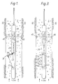
- a conventional well logging sonde 18 contains a conventional type transducer, which is an ultrasonic crystal 23.
- Electronics 29 provide electrical pulses to transmitter crystal 23, as hereinafter explained, to provide acoustical pulses into the fluid flow.
- the acoustical pulses pass through the fluid containing particles 14 and impinge upon another transducer, which is a crystal 33, mounted on an arm 36.
- Arm 36 is initially closed and forms part of sonde 18 as sonde 18 is lowered into and removed from borehole 5.
- Actuator means 40 is controlled by signals as hereinafter explained to either extend the actuator arm 36 for measurement purposes or to bring it into an initial position for movement of sonde 18 through the borehole. As explained hereinafter during a measurement, the roles of crystals 23, 33 are reversed.
- Crystal 23 or 33 provides electrical pulses back to electronics 29 in accordance with the received acoustical pulses.
- Electronics 29 processes the signal from crystal 23 or 33 and provides a travel-time signal in accordance therewith.
- a conventional caliper log means 43 has pads 45 and 46 urged against the wall of borehole 5, by arms 47 and 48, respectively, so as to centralize sonde 18 in borehole 5.
- Caliper means 43 also provides a signal representative of the diameter of borehole 5 in accordance with the positioning of pads 45 and 46.
- Electronics 29 includes a pulse source 52 connected to switching means 54 and to cable means 56 and receiving a signal from cable means 56 to provide a pulse to switching means 54.
- Switching means 54 is also connected to crystals 23, 33 and to cable means 56. Switching means 54 is controlled by a control signal from cable means 56 during one part of a measurement to provide the pulse from pulse source 52 to crystal 23 and during another part of the measure to provide the pulse from pulse source 52 to crystal 33.
- Pulse source 52 also provides a pulse to a set input of a flip-flop 60.
- Flip-flop 60 has its clear input connected to switching means 54 which provides an electrical pulse corresponding to the first arrival signal from crystal 33 to flip-flop 60 during the one part of the measurement and a similarly-derived signal from crystal 23 during the other part of the measurement.
- An output of flip-flop 60 is provided to an AND gate 64 which also receives timing pulses from a clock 69. AND gate 64 provides its output to cable means 56.
- the output of AND gate 64 will correspond to the transit time for the acoustical pulse to be transmitted from crystal 23 or 33 through the water to crystal 33 or 23. This is accomplished by pulse source 52 providing a pulse to the input of flip-flop 60, triggering flip-flop 60 to a set state thereby causing flip-flop 60 to provide an enabling signal to AND gate 64.
- the enabling signal causes AND gate 64 to pass the timing pulses from clock 69 to cable means 56.
- Clock 69 is tied to microprocessor 80 by providing pulses to cable means 56 so as to provide synchronized timing of the system.
- crystal 23 or 33 When crystal 23 or 33 receives an acoustical pulse, it provides an electrical pulse, by way of switching means 54, to the clear input of flip-flop 60 triggering flip-flop 60 to its clear state thereby terminating the enabling signal.
- the termination of the enabling signal causes AND gate 64 to block the timing pulses from clock 69. Therefore the timing pulses passed by AND gate 64 represent the time of travel of the acoustical pulse from one crystal 23 or 33 to the other crystal 33 or 23.
- Cable means 56 provides the passed timing pulses uphole to microprocessor means 80. Cable means 56 also provides the signal from caliper log means 43 uphole to microprocessor means 80. Microprocessor means 80 provides signals to cable means 56 for triggering pulse source 52, and for controlling actuator means 40 and switching means 54. It should be noted that the time between triggering of pulse source 52 should be sufficient to allow any ringing of crystal 33 or 23 by acoustical pulses to have died down so that the next transit time measurement is not inadvertently terminated early by a ringing from the previous part of the measurement.
- microprocessor means 80 will receive pulses corresponding to two travel times for each measurement.
- Calibration of the system may be accomplished prior to logging in a flow loop or during logging by running at several different cable speeds.
- the calibrated fluid velocity will be exact if the tool is run stationary. During a logging run where the tool is moving upwards, the actual fluid velocity will be the indicated velocity minus the velocity of the cable.
- the diameter of the borehole or the casing is obtained from a caliper log means 43.
- the diameter of the sonde 18 is standard 4,3 cm (1 11/16 inches).
- arm 36 is eliminated as is actuator means 40.
- Crystals 23 and 33 are positioned so that the acoustical pulses reflect off the walls of borehole 5 and sonde 18 until they impinge on one of the crystals 23 or 33.
- the operation of this embodiment is essentially the same as the first embodiment.
Landscapes
- Physics & Mathematics (AREA)
- Fluid Mechanics (AREA)
- Life Sciences & Earth Sciences (AREA)
- General Physics & Mathematics (AREA)
- Electromagnetism (AREA)
- Engineering & Computer Science (AREA)
- Geology (AREA)
- Mining & Mineral Resources (AREA)
- Acoustics & Sound (AREA)
- Geophysics (AREA)
- Environmental & Geological Engineering (AREA)
- General Life Sciences & Earth Sciences (AREA)
- Geochemistry & Mineralogy (AREA)
- Geophysics And Detection Of Objects (AREA)
Applications Claiming Priority (1)
| Application Number | Priority Date | Filing Date | Title |
|---|---|---|---|
| US07/251,276 US4982383A (en) | 1988-09-30 | 1988-09-30 | Downhole ultrasonic transit-time flowmetering means and method |
Publications (2)
| Publication Number | Publication Date |
|---|---|
| EP0481141A1 EP0481141A1 (en) | 1992-04-22 |
| EP0481141B1 true EP0481141B1 (en) | 1994-08-31 |
Family
ID=22951238
Family Applications (1)
| Application Number | Title | Priority Date | Filing Date |
|---|---|---|---|
| EP90311468A Expired - Lifetime EP0481141B1 (en) | 1988-09-30 | 1990-10-18 | Borehole fluid flow monitoring apparatus |
Country Status (4)
| Country | Link |
|---|---|
| US (1) | US4982383A (da) |
| EP (1) | EP0481141B1 (da) |
| DE (1) | DE69012125T2 (da) |
| DK (1) | DK0481141T3 (da) |
Families Citing this family (15)
| Publication number | Priority date | Publication date | Assignee | Title |
|---|---|---|---|---|
| EP0555049B1 (en) * | 1992-02-05 | 1998-10-07 | Canon Kabushiki Kaisha | Magnetooptical information recording/reproducing apparatus |
| CA2107043A1 (en) * | 1993-09-27 | 1995-03-28 | Wolfgang Stedtnitz | Method and apparatus for measuring water velocities and discharges in rivers and the like |
| GB2318414B (en) * | 1996-10-19 | 2001-02-14 | Univ Cranfield | Improvements relating to flow measurement |
| CA2321539C (en) * | 1998-03-06 | 2008-02-12 | Shell Canada Limited | Inflow detection apparatus and system for its use |
| US6629564B1 (en) | 2000-04-11 | 2003-10-07 | Schlumberger Technology Corporation | Downhole flow meter |
| US6584860B1 (en) * | 2002-01-14 | 2003-07-01 | Murray F. Feller | Flow probe insertion gauge |
| US6848189B2 (en) | 2003-06-18 | 2005-02-01 | Halliburton Energy Services, Inc. | Method and apparatus for measuring a distance |
| CN100359130C (zh) * | 2004-11-09 | 2008-01-02 | 中国石化胜利油田有限公司纯梁采油厂 | 利用直读式超声波流量计检测套管漏失点的方法 |
| US7967081B2 (en) * | 2006-11-09 | 2011-06-28 | Smith International, Inc. | Closed-loop physical caliper measurements and directional drilling method |
| US8118114B2 (en) * | 2006-11-09 | 2012-02-21 | Smith International Inc. | Closed-loop control of rotary steerable blades |
| CA2835891C (en) | 2011-06-22 | 2016-04-05 | Piezotech, Llc | System and device for acoustic measuring in a medium |
| WO2014032083A1 (en) * | 2012-08-28 | 2014-03-06 | Rubicon Research Pty Ltd | Flow meter with acoustic array |
| FR3035498B1 (fr) * | 2015-04-23 | 2020-04-24 | Integra Metering Sas | Debitmetre pour la mesure d'un debit de fluide a l'exterieur d'un corps tubulaire et vanne l'incorporant |
| US11680484B2 (en) * | 2021-03-08 | 2023-06-20 | Saudi Arabian Oil Company | System and method for mixed water salinity characterization |
| US12352609B2 (en) | 2022-12-07 | 2025-07-08 | Saudi Arabian Oil Company | Fluid flow velocity measurement via thermal conduction |
Family Cites Families (9)
| Publication number | Priority date | Publication date | Assignee | Title |
|---|---|---|---|---|
| CH359896A (de) * | 1958-05-08 | 1962-01-31 | Foerderung Forschung Gmbh | Verfahren und Anordnung zur Geschwindigkeits- und Mengenmessung strömender Flüssigkeiten mittels Ultraschall |
| US3603145A (en) * | 1969-06-23 | 1971-09-07 | Western Co Of North America | Monitoring fluids in a borehole |
| JPS5433542B2 (da) * | 1973-06-23 | 1979-10-22 | ||
| US3906791A (en) * | 1973-10-01 | 1975-09-23 | Panametrics | Area averaging ultrasonic flowmeters |
| US4452077A (en) * | 1982-07-19 | 1984-06-05 | Atlantic Richfield Company | Borehole ultrasonic flow meter |
| US4596133A (en) * | 1983-07-29 | 1986-06-24 | Panametrics, Inc. | Apparatus and methods for measuring fluid flow parameters |
| GB8430217D0 (en) * | 1984-11-30 | 1985-01-09 | Redding R J | Electronic gas meter |
| DE3809189A1 (de) * | 1987-03-20 | 1988-09-29 | Noriyoshi Chubachi | Verfahren und vorrichtung zur messung der flussgeschwindigkeit mit ultraschallwellen |
| US4905203A (en) * | 1988-09-30 | 1990-02-27 | Texaco Inc. | Downhole doppler flowmeter |
-
1988
- 1988-09-30 US US07/251,276 patent/US4982383A/en not_active Expired - Fee Related
-
1990
- 1990-10-18 DK DK90311468.4T patent/DK0481141T3/da active
- 1990-10-18 DE DE69012125T patent/DE69012125T2/de not_active Expired - Fee Related
- 1990-10-18 EP EP90311468A patent/EP0481141B1/en not_active Expired - Lifetime
Also Published As
| Publication number | Publication date |
|---|---|
| US4982383A (en) | 1991-01-01 |
| DE69012125D1 (de) | 1994-10-06 |
| DK0481141T3 (da) | 1994-10-03 |
| DE69012125T2 (de) | 1994-12-22 |
| EP0481141A1 (en) | 1992-04-22 |
Similar Documents
| Publication | Publication Date | Title |
|---|---|---|
| US4905203A (en) | Downhole doppler flowmeter | |
| EP0481141B1 (en) | Borehole fluid flow monitoring apparatus | |
| US4947683A (en) | Pulsed ultrasonic doppler borehole fluid measuring apparatus | |
| CA2473317C (en) | Method for reservoir navigation using formation pressure testing measurement while drilling | |
| US6550345B1 (en) | Technique for measurement of gas and liquid flow velocities, and liquid holdup in a pipe with stratified flow | |
| US8689904B2 (en) | Detection of gas influx into a wellbore | |
| US7281415B2 (en) | Non-intrusive multiphase flow meter | |
| US5341345A (en) | Ultrasonic stand-off gauge | |
| US4527425A (en) | System for detecting blow out and lost circulation in a borehole | |
| US4345480A (en) | Rotary flow meter | |
| US6769293B2 (en) | Detection of liquid in gas pipeline | |
| WO2008117030A1 (en) | Flow measuring apparatus using tube waves and corresponding method | |
| CN103906998A (zh) | 用于确定流速的井下工具 | |
| US4452077A (en) | Borehole ultrasonic flow meter | |
| EP3343184A1 (en) | Multiphase vortex flow meter | |
| US5661236A (en) | Pad production log tool | |
| US9366133B2 (en) | Acoustic standoff and mud velocity using a stepped transmitter | |
| EP0664442A2 (en) | Torque flow-meter | |
| US5749417A (en) | Production log | |
| US4979112A (en) | Method and apparatus for acoustic measurement of mud flow downhole | |
| CA2027192A1 (en) | Downhole ultrasonic transit-time flowmetering means and method | |
| CA2539609C (en) | Inferential densometer and mass flowmeter | |
| CA2009977A1 (en) | Downhole doppler flowmeter | |
| SU1209838A1 (ru) | Способ наблюдени за оттоком и притоком жидкости в бур щихс скважинах и устройство дл его осуществлени | |
| EP0584998A2 (en) | Method and device for detecting pressure pulses |
Legal Events
| Date | Code | Title | Description |
|---|---|---|---|
| PUAI | Public reference made under article 153(3) epc to a published international application that has entered the european phase |
Free format text: ORIGINAL CODE: 0009012 |
|
| AK | Designated contracting states |
Kind code of ref document: A1 Designated state(s): DE DK GB |
|
| 17P | Request for examination filed |
Effective date: 19920930 |
|
| 17Q | First examination report despatched |
Effective date: 19921116 |
|
| GRAA | (expected) grant |
Free format text: ORIGINAL CODE: 0009210 |
|
| AK | Designated contracting states |
Kind code of ref document: B1 Designated state(s): DE DK GB |
|
| PGFP | Annual fee paid to national office [announced via postgrant information from national office to epo] |
Ref country code: DK Payment date: 19940920 Year of fee payment: 5 |
|
| PGFP | Annual fee paid to national office [announced via postgrant information from national office to epo] |
Ref country code: GB Payment date: 19940928 Year of fee payment: 5 |
|
| REG | Reference to a national code |
Ref country code: DK Ref legal event code: T3 |
|
| REF | Corresponds to: |
Ref document number: 69012125 Country of ref document: DE Date of ref document: 19941006 |
|
| PGFP | Annual fee paid to national office [announced via postgrant information from national office to epo] |
Ref country code: DE Payment date: 19941230 Year of fee payment: 5 |
|
| PLBE | No opposition filed within time limit |
Free format text: ORIGINAL CODE: 0009261 |
|
| STAA | Information on the status of an ep patent application or granted ep patent |
Free format text: STATUS: NO OPPOSITION FILED WITHIN TIME LIMIT |
|
| 26N | No opposition filed | ||
| PG25 | Lapsed in a contracting state [announced via postgrant information from national office to epo] |
Ref country code: GB Effective date: 19951018 Ref country code: DK Effective date: 19951018 |
|
| REG | Reference to a national code |
Ref country code: DK Ref legal event code: EBP |
|
| GBPC | Gb: european patent ceased through non-payment of renewal fee |
Effective date: 19951018 |
|
| PG25 | Lapsed in a contracting state [announced via postgrant information from national office to epo] |
Ref country code: DE Effective date: 19960702 |