EP0481275A1 - Dispositif de changement d'outil pour une machine-outil - Google Patents
Dispositif de changement d'outil pour une machine-outil Download PDFInfo
- Publication number
- EP0481275A1 EP0481275A1 EP91116673A EP91116673A EP0481275A1 EP 0481275 A1 EP0481275 A1 EP 0481275A1 EP 91116673 A EP91116673 A EP 91116673A EP 91116673 A EP91116673 A EP 91116673A EP 0481275 A1 EP0481275 A1 EP 0481275A1
- Authority
- EP
- European Patent Office
- Prior art keywords
- jaws
- jaw
- tool changer
- gripper
- closed position
- Prior art date
- Legal status (The legal status is an assumption and is not a legal conclusion. Google has not performed a legal analysis and makes no representation as to the accuracy of the status listed.)
- Granted
Links
Images


Classifications
-
- B—PERFORMING OPERATIONS; TRANSPORTING
- B25—HAND TOOLS; PORTABLE POWER-DRIVEN TOOLS; MANIPULATORS
- B25J—MANIPULATORS; CHAMBERS PROVIDED WITH MANIPULATION DEVICES
- B25J15/00—Gripping heads and other end effectors
- B25J15/02—Gripping heads and other end effectors servo-actuated
- B25J15/0206—Gripping heads and other end effectors servo-actuated comprising articulated grippers
-
- B—PERFORMING OPERATIONS; TRANSPORTING
- B23—MACHINE TOOLS; METAL-WORKING NOT OTHERWISE PROVIDED FOR
- B23Q—DETAILS, COMPONENTS, OR ACCESSORIES FOR MACHINE TOOLS, e.g. ARRANGEMENTS FOR COPYING OR CONTROLLING; MACHINE TOOLS IN GENERAL CHARACTERISED BY THE CONSTRUCTION OF PARTICULAR DETAILS OR COMPONENTS; COMBINATIONS OR ASSOCIATIONS OF METAL-WORKING MACHINES, NOT DIRECTED TO A PARTICULAR RESULT
- B23Q3/00—Devices holding, supporting, or positioning work or tools, of a kind normally removable from the machine
- B23Q3/155—Arrangements for automatic insertion or removal of tools, e.g. combined with manual handling
- B23Q3/1552—Arrangements for automatic insertion or removal of tools, e.g. combined with manual handling parts of devices for automatically inserting or removing tools
- B23Q3/1554—Transfer mechanisms, e.g. tool gripping arms; Drive mechanisms therefore
-
- B—PERFORMING OPERATIONS; TRANSPORTING
- B23—MACHINE TOOLS; METAL-WORKING NOT OTHERWISE PROVIDED FOR
- B23Q—DETAILS, COMPONENTS, OR ACCESSORIES FOR MACHINE TOOLS, e.g. ARRANGEMENTS FOR COPYING OR CONTROLLING; MACHINE TOOLS IN GENERAL CHARACTERISED BY THE CONSTRUCTION OF PARTICULAR DETAILS OR COMPONENTS; COMBINATIONS OR ASSOCIATIONS OF METAL-WORKING MACHINES, NOT DIRECTED TO A PARTICULAR RESULT
- B23Q3/00—Devices holding, supporting, or positioning work or tools, of a kind normally removable from the machine
- B23Q3/155—Arrangements for automatic insertion or removal of tools, e.g. combined with manual handling
- B23Q3/1552—Arrangements for automatic insertion or removal of tools, e.g. combined with manual handling parts of devices for automatically inserting or removing tools
- B23Q3/1554—Transfer mechanisms, e.g. tool gripping arms; Drive mechanisms therefore
- B23Q2003/155404—Transfer mechanisms, e.g. tool gripping arms; Drive mechanisms therefore the transfer mechanism comprising a single gripper
-
- Y—GENERAL TAGGING OF NEW TECHNOLOGICAL DEVELOPMENTS; GENERAL TAGGING OF CROSS-SECTIONAL TECHNOLOGIES SPANNING OVER SEVERAL SECTIONS OF THE IPC; TECHNICAL SUBJECTS COVERED BY FORMER USPC CROSS-REFERENCE ART COLLECTIONS [XRACs] AND DIGESTS
- Y10—TECHNICAL SUBJECTS COVERED BY FORMER USPC
- Y10S—TECHNICAL SUBJECTS COVERED BY FORMER USPC CROSS-REFERENCE ART COLLECTIONS [XRACs] AND DIGESTS
- Y10S483/00—Tool changing
- Y10S483/902—Tool grippers
-
- Y—GENERAL TAGGING OF NEW TECHNOLOGICAL DEVELOPMENTS; GENERAL TAGGING OF CROSS-SECTIONAL TECHNOLOGIES SPANNING OVER SEVERAL SECTIONS OF THE IPC; TECHNICAL SUBJECTS COVERED BY FORMER USPC CROSS-REFERENCE ART COLLECTIONS [XRACs] AND DIGESTS
- Y10—TECHNICAL SUBJECTS COVERED BY FORMER USPC
- Y10T—TECHNICAL SUBJECTS COVERED BY FORMER US CLASSIFICATION
- Y10T279/00—Chucks or sockets
- Y10T279/18—Pivoted jaw
-
- Y—GENERAL TAGGING OF NEW TECHNOLOGICAL DEVELOPMENTS; GENERAL TAGGING OF CROSS-SECTIONAL TECHNOLOGIES SPANNING OVER SEVERAL SECTIONS OF THE IPC; TECHNICAL SUBJECTS COVERED BY FORMER USPC CROSS-REFERENCE ART COLLECTIONS [XRACs] AND DIGESTS
- Y10—TECHNICAL SUBJECTS COVERED BY FORMER USPC
- Y10T—TECHNICAL SUBJECTS COVERED BY FORMER US CLASSIFICATION
- Y10T483/00—Tool changing
- Y10T483/17—Tool changing including machine tool or component
- Y10T483/1733—Rotary spindle machine tool [e.g., milling machine, boring, machine, grinding machine, etc.]
- Y10T483/1748—Tool changer between spindle and matrix
Definitions
- the invention relates to a tool changer for tools of a machine tool, with a gripper, on which two movable jaws are arranged for the form-fitting gripping of the tools, on which an actuating member is axially displaceably mounted in the longitudinal direction, which the jaws about their respective pivot axis in a spread position for insertion and executing the tools or pivoted into a closed position for the form-fitting gripping of the tools, and on each of which an opening gear and a locking gear are arranged between the actuating member and each of the two jaws, of which each of the two opening gear each has an inclined surface provided on the actuating member has, which cooperates to open the respective jaw with a counter surface provided on the jaw, and of which each of the two locking gears each has a guide bevel provided on the actuating member, each for closing the respective jaw an associated rolling element cooperates with a bearing surface arranged on the jaw, the two locking gears positively locking the jaws in the closed position.
- Such a tool changer is known from DE-OS-3 717 201.
- the known tool changer is used in modern machine tools, in particular so-called machining centers, in which a large number of machining steps are successively carried out on a large number of workpieces under program control.
- the various tools are kept ready in a magazine near the headstock in these machine tools, so that when changing from one machining step to the next, the previously used tool is replaced by a gripper and a new tool is inserted from the magazine into the spindle for the next machining step can.
- the known tool changer has a movable arm and a gripper arranged at the free end of the arm.
- the known gripper is provided with two fixed jaws, which are arranged at a distance from one another such that the respective tool is guided axially between these fixed jaws in a form-fitting manner. Furthermore, two movable jaws are provided on the known gripper, which, in their closed position, positively engage around the tool received between the fixed jaws. In the spread position of the movable jaws, the respective tool can be removed from the fixed jaws or inserted between them.
- the movable jaws are opened using an actuation button which is moved against a fixed stop provided on the machine tool for this purpose.
- the actuating button is spring-loaded, so that when leaving the fixed stop, the actuating button is pushed back into its rest position, in which it holds the movable jaws in their closed position.
- the actuating button is connected to a bolt designed as an actuating element for the movable jaws, an opening gear and a closing gear being provided between the bolt and each of the two movable jaws.
- the bolt has four guide bevels on its outer circumference, which run in the longitudinal direction of the bolt and radially from the inside to the outside.
- the guide slopes each interact via a ball with contact surfaces provided on the jaws.
- the guide bevels are assigned to one another in pairs and are designed such that in the two axial end positions of the bolt two balls enter the guide bevels and the other two balls emerge from the guide bevels. This radial movement of the balls during the axial displacement of the bolt is used to forcibly move the movable jaws back and forth between the closed position and the spreading position.
- two oppositely running guide rails each interact with one of the movable jaws.
- the one guide slope is part of the opening gear while the other guide slope is part of the closing gear.
- the two balls of the two locking gears which have stepped radially outward rest on the one hand on the outer peripheral surface of the bolt and on the other hand on the contact surface of the respective jaw, so that they lock the jaws in a form-fitting manner.
- the force of the compression spring biasing the actuating button counteracts a force possibly exerted on the jaws from outside for transferring the same into the spreading position.
- the holding force of the movable jaws is therefore determined by the tension force of the compression spring.
- the opening and closing gears are structurally complex and must also be designed to be adjustable because of the forced actuation of the jaws in order to prevent the entire actuation mechanism from jamming. Furthermore, it is disadvantageous that when the tension force of the spring decreases, the holding force of the known gripper decreases or is completely lost when the spring breaks. In order to prevent the tool from falling out of the gripper To limit damage to the machine tool, fixed jaws are additionally provided on the known gripper, which fix the tool at least in the axial direction. But this also leads to an undesirably high design effort.
- a tool changer is known from DD-PS 149 331, the gripper of which has two movable jaws which are forcibly opened or closed via a toggle lever mechanism.
- the toggle lever mechanism is operated via a push rod that is biased into the closed position of the jaws by a compression spring.
- a hydraulic piston is provided for moving the jaws into the spread position, which moves the push rod against the force of the spring.
- the holding force is determined by the clamping force of a compression spring.
- the spring will slacken or break, which can lead to the tool being held flying out of the gripper and causing damage to the machine tool, particularly when the tool changer is moving quickly and suddenly.
- the invention is therefore based on the object of developing a tool changer of the type mentioned in such a way that the disadvantages mentioned above are avoided.
- a reliable function of the tool changer should be ensured with a simple structure.
- the tool should always be held securely in the gripper even during rapid and jerky movements and the working accuracy of the machine tool should not be impaired by the opening and closing of the gripper.
- the actuating member is designed as a piston rod of a double-acting medium-actuated push piston, which is arranged in the gripper, that the inclined surfaces of the opening gear can be brought into contact with the counter surfaces for opening and that the inclined surfaces during closing and in the closed position of the jaws are out of engagement with the counter surfaces.
- the object underlying the invention is completely achieved in this way. Because the jaws are opened and closed using a medium-actuated push piston, it is no longer necessary to approach a fixed stop to open the gripper. In addition, a spring is no longer required, which biases the jaws into their closed position, so that all disadvantages associated with a spring are avoided. Rather, the jaws are kept closed by the hydraulically or compressed-air thrust piston.
- the opening gear is inoperative during closing, there is no permanent forced guidance of the jaws, so that an adjustment can be dispensed with. Since the inclined surfaces are disengaged from the counter surfaces during closing, the entire actuating mechanism of the gripper cannot jam. All this leads to a structurally simple construction of the tool changer according to the invention. It is particularly advantageous that to open the jaws, the inclined surfaces provided on the piston rod only have to be brought into contact with the counter surfaces on the jaws.
- the opening gears are thus designed, so to speak, as simple thrust gears; the jaws are pivoted into their spreading position by the pressure of the inclined surfaces on the counter surfaces. This also contributes to the structurally simple structure of the gripper.
- the two locking gears lock the jaws in the closed position in a self-locking manner.
- This measure has the advantage that the tool is still securely held in the gripper even if the hydraulic or compressed air fails.
- the rolling element is a roller which is inserted in a bore in the respective jaw parallel to its pivot axis, in which the roller is radially secured, the bore with its inner wall forming the contact surface, and when the bore unites has parallel to the pivot axis continuous longitudinal slot through which the roller at least in the closed position over a portion of its circumferential surface with the associated guide slope in Anla ghost.
- the roller is held securely in a structurally simple manner.
- the holder of the roller also represents the contact surface of the locking mechanism, which is also advantageous from a design point of view.
- each jaw there is provided a channel which cuts the bore transversely and is open towards the other jaw into which the piston rod projects with its free end pointing away from the thrust piston, and when the free end of the piston rod has on both sides of the rollers facing the guide bevels which extend obliquely outwards from the thrust piston at an angle to the longitudinal direction, the angle being less than 15 °, preferably less than 10 ".
- the guide bevels gradually merge into radially inwardly recesses in the direction of the thrust piston, in which the rollers come to rest in the spread position of the jaws.
- the piston rod has the inclined surfaces on its end face pointing away from the thrust piston, and if the counter surfaces provided on the jaws are aligned approximately radially to the axis of rotation of the respective jaw.
- the opening gear acting as a thrust gear is realized in a structurally simple manner so that even small strokes and forces are sufficient to open the jaws.
- the piston rod only has to be moved with its end face against the counter surfaces of the jaws, which convert the entire contact force of the end face into a force for opening or pivoting the jaws because of their radial alignment with the axis of rotation of the jaw.
- the end face of the piston rod is spherical, and if the counter faces are arranged in the respective channel and the end face is curved accordingly.
- each jaw has a stop surface, which each interacts with an adjustable stop in order to limit the closing movement of the jaws.
- This measure has the advantage that damage to the tool due to an excessive closing force of the thrust piston can be avoided.
- the gripper itself is prevented from being damaged if it is closed without having picked up a tool.
- each of the jaws is assigned a control element for displaying the respective position of the jaw.
- control element has an inductive proximity sensor.
- This measure is structurally particularly simple, since the jaws are made of metal, so that pivoting of the jaws can be detected directly by the inductive sensor.
- the thrust piston has at least one channel running in the longitudinal direction and opening in the vicinity of the guide slopes for supplying the rolling elements with a lubricant, the channel being closed during operation of the gripper.
- the channel provided in the thrust piston only has to be opened to lubricate the rollers, which is possible, for example, by unscrewing a grub screw inserted in it in order to bring grease and / or oil into the area of the rollers.
- 10 denotes a tool changer overall, which is provided for gripping and holding a tool, which is indicated schematically at 11.
- An arm 12 of the tool changer 10 is only shown broken off in FIG. 1, it generally runs initially obliquely and then perpendicularly out of the drawing plane of FIG. 1, while a gripper 13 of the tool changer 10 extends in the drawing plane.
- the jaws 14 and 15 designate two movable jaws of the gripper 13, which are in their closed position in FIG. 1.
- the jaws 14 and 15 can be pivoted about their pivot axes indicated at 16 and 17 so that they assume their spread position.
- the jaws 14 'and 15' in the spread position are shown in broken lines in FIG. 1. As can be seen, the jaws 14 and 15 move laterally apart during the transition into their spread position shown in dashed lines, whereby they partially emerge from the gripper 13 or from the housing indicated at 18.
- the jaws 14 and 15 are curved and have an axial profile 19 which is adapted to the tool 11, which is provided with a corresponding axial profile 20.
- the dimensions are such that the jaws 14 and 15 hold the tool 11 positively in its closed position, as is known per se and need not be explained again in the context of the present invention.
- the gripper 13 has at its rear end 21, which is remote from the bakken 14 and 15, two olives 22 and 23 which serve to supply the gripper 13 with compressed air or hydraulic oil.
- the olive 22 is acted upon with medium in the direction of an arrow indicated at 24 in order to open the jaws 14 and 15 in a manner to be described in more detail, while the olive 23 is acted upon in the direction of an arrow indicated at 25 around the jaws 14 and 15 to close in a manner to be described as well.
- FIG. 1 two side cover caps 28 and 29 provided on the gripper 13 can be seen in FIG. 1, which are designed to be removable and cover adjusting screws to be described, which serve as a stop for the jaws 14 and 15 in the closed position.
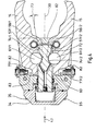
- the gripper 13 is shown in a sectional view along a plane 11-11, in which the gripper 13 lies with its longitudinal direction indicated at 30. It can be seen that the housing 18 of the gripper 13 has a cover plate 32, a base plate 33 and a cap 34 arranged at the rear end 21 of the gripper 13.
- the cover plate 32 and the base plate 33 are connected to one another by means of a screw indicated at 35, while the cap 34 is screwed onto the cover plate 32 and the base plate 33 with the aid of screws 36 shown in FIG. 1.
- a sealing ring 37 is arranged between the cap 34 and the cover plate 32 and the base plate 33, so that an interior 38 which is sealed off from the outside in a pressure-tight manner is formed in the gripper 13.
- the interior 38 is connected via holes 39 and 40 to the olives 22 and 23 which can be seen in FIG. 1.
- a thrust piston 42 is mounted longitudinally displaceably in the interior 38 and can be moved back and forth in the direction of a double arrow indicated at 43. By introducing compressed air through the bore 39, the thrust piston 42 is moved to the right in FIG. 2, while it is moved to the left when compressed air is introduced into the interior 38 via the bore 40.
- the guidance and sealing of the thrust piston 42 required for this purpose takes place at its rear end 44 by means of an O-ring indicated at 45 and is known per se, so that it need not be explained further here.
- the push piston 42 has a shaft 47 pointing away from its rear end 44, which is guided between the cover plate 32 and the base plate 33 by means of an O-ring / support ring arrangement, also indicated in a pressure-tight manner, in a known manner.
- the push piston 42 is connected to a piston rod 51, which is tapered in a direction indicated at 52 transverse to the longitudinal direction 30 of the gripper 13 with respect to the shaft 47.
- the piston rod 51 which is spherical on its end face 54, projects into a channel 55, which is related to the transverse direction 52 runs approximately centrally in the jaw 14.
- the channel 14 has a front curved wall 56 on the right in FIG. 2, which is adapted as a counter surface 57 to the end face 54 of the piston rod 51.
- FIG. 2 also shows a roller 61 arranged behind the piston rod 51, which is inserted in a bore indicated at 62, which is provided in the jaw 14.
- the bore 62 is cut transversely by the channel 55, so that the channel 55 between its upper channel wall 63 and its lower channel wall 64 makes the roller 61 partially accessible.
- the roller 61 is secured axially by the cover plate 32 and the base plate 33 and radially by the bore 62.
- Fig. 2 can also be seen that the jaw 14 extends with its inner end 65 to behind the shaft 47 of the push piston 42.
- the gripper 13 is shown in section along the line 111-111 from FIG. 2, so that the upper channel wall 63 cannot be seen, while the lower channel wall 64 is indicated by dashed lines under the piston rod 51.
- the thrust piston 42 and thus the piston rod 51 are moved to the right in FIG. 3, namely by introducing compressed air or oil into the olive 22, the end face 54 comes with its inclined surfaces 58/1 and 58/2 with the counter surfaces 57/1 or 57/2 of the jaws 14 or 15 in contact and pivots the jaws 14 and 15 in the direction of the arrow 67/1 or 67/2.
- the counter surfaces 57/1 and 57/2 are aligned radially to the pivot axes 16 and 17, so that the pressing force of the end face 54 is converted directly into the pivoting movement of the jaws 14 and 15.
- the roller 61/2 lies with a part of its circumferential sections 69 and 70 against a guide bevel 72 which is provided on the side of the piston rod 51.
- the guide bevel 72 runs obliquely outwards in the direction of the end face 54 and, with the longitudinal direction 30 of the piston rod 51, adjoins an angle indicated at 73 in FIG. 4, which is approximately 6 °.
- the guide bevel 72 merges in the direction of the thrust piston 42 into a radially inwardly curved recess 74/2, in which the roller 61/2 comes to rest when the piston rod executes the stroke 59.
- the jaws 14 and 15 and the piston rod 51 are mirror images of the longitudinal direction 30, so that the respective features are described in connection with one of the two jaws 14 or 15 for the sake of clarity.
- FIG. 3 no tool 11 is received between the jaws 14 and 15.
- the jaws 14 and 15 shown in the closed position rest on their inner ends 65 each with a stop surface 75 on an linear stop 77, which is formed by an adjustable screw 78.
- the screws 78 are covered by the cover caps 28 and 29 shown in FIG. 1.
- a channel 80 is provided which is closed by a grub screw 79 and extends in the longitudinal direction and branches into two side channels 81.
- the side channels 81 open in the area of the recesses 74.
- the jaws 14 and 15 are guided in the longitudinal direction 30, in addition to their pivot axes 16 and 17, also through housing parts 82 'and 82 ", which are provided to relieve the pivot axes 16 and 17.
- the front housing part 82' is part of the cover plate 32 while the rear Housing parts 82 "are parts of the base plate 33.
- the previously mentioned inductive proximity switches 26 and 27 are not shown in the drawing, only their measurement spot is indicated at 83.
- the measurement spot lies on the inner ends 65 of the jaws 14 and 15, while in the spread position of the jaws 14 and 15 shown in FIG. 4 it lies next to the inner ends 65. Since the jaws 14 and 15 are made of metal, the inductive proximity sensors emit different signals, depending on whether the jaws 14 and 15 are in their spread position or in their closed position or are transferred to these positions.
- the rollers 61/2 and 61/1 are located in the recesses 64/2 and 64/1 of the piston rod 51.
- the inclined surfaces 58/1 and 58/2 are in contact with the counter surfaces 57/1 and 57/2 of the jaws 14 and 15 and thereby keep the jaws 14 and 15 open.
- the thrust piston 42 consequently exerts a force in the direction of the arrow 43 ′′.
- This mechanism is therefore self-adjusting, even when the swivel axes 16, 17 are knocked out, the gripper 13 is closed securely and reproducibly. This is done in that the jaws 14 and 15 have gripped a tool 11 with their axial profile 19, and in that the jaws 14 and 15, on the other hand, come into contact with the adjustable stops 77 with their stop faces 75. Each jaw 14, 15 is thus clamped between stop 77 and tool 11 or pivot axis 16, 17.
- the adjustable stops 77 ensure that the jaws 14, 15 always grip a tool 11 centrally. On the other hand, clamping the jaws 14, 15 against the stops 77 ensures that the piston rod 51 does not have to absorb any transverse forces when the gripper 13 is closed.
- rollers 61 are clamped between the contact surfaces 71 of the bores 62 on the one hand and the guide bevels 72 on the other hand.
- the angle 73 of the inclined surfaces with respect to the longitudinal axis 30 is so small that the locking mechanism formed by the inclined surface 72, the roller 61 and the contact surface 71 acts in a self-locking manner.
- the material-dependent angle of friction between roller 61 and guide bevel 72 or roller 61 and contact surface 71 is greater than the wedge angle that angle 73 represents.
- the locking mechanism is consequently a type of wedge mechanism in which self-locking occurs.
- the gripper 13 can only be opened in that an overpressure is generated via the olive 22 in the interior 38, which pushes the thrust piston 42 in the direction of the arrow 43 ".
Landscapes
- Engineering & Computer Science (AREA)
- Mechanical Engineering (AREA)
- Robotics (AREA)
- Automatic Tool Replacement In Machine Tools (AREA)
- Manipulator (AREA)
Applications Claiming Priority (2)
| Application Number | Priority Date | Filing Date | Title |
|---|---|---|---|
| DE4031996A DE4031996A1 (de) | 1990-10-09 | 1990-10-09 | Werkzeugwechsler fuer werkzeuge einer werkzeugmaschine |
| DE4031996 | 1990-10-09 |
Publications (2)
| Publication Number | Publication Date |
|---|---|
| EP0481275A1 true EP0481275A1 (fr) | 1992-04-22 |
| EP0481275B1 EP0481275B1 (fr) | 1994-07-27 |
Family
ID=6415927
Family Applications (1)
| Application Number | Title | Priority Date | Filing Date |
|---|---|---|---|
| EP91116673A Expired - Lifetime EP0481275B1 (fr) | 1990-10-09 | 1991-09-30 | Dispositif de changement d'outil pour une machine-outil |
Country Status (5)
| Country | Link |
|---|---|
| US (1) | US5277689A (fr) |
| EP (1) | EP0481275B1 (fr) |
| JP (1) | JP2632264B2 (fr) |
| DE (2) | DE4031996A1 (fr) |
| ES (1) | ES2061143T3 (fr) |
Cited By (5)
| Publication number | Priority date | Publication date | Assignee | Title |
|---|---|---|---|---|
| USD539002S1 (en) | 2006-02-08 | 2007-03-20 | Whiteside Mfg. Co. | Set of creeper ends |
| EP2551052A1 (fr) * | 2011-07-29 | 2013-01-30 | A Ingenieria de Automatismos, S.A. | Changeur d'outil à deux doigts |
| DE102014014105A1 (de) * | 2014-09-24 | 2016-03-24 | Festo Ag & Co. Kg | Greifvorrichtung |
| WO2016041780A3 (fr) * | 2014-09-19 | 2016-05-12 | Homag Holzbearbeitungssysteme Gmbh | Dispositif de préhension pour un outil d'usinage, système de stockage et procédé |
| CN117464416A (zh) * | 2022-07-29 | 2024-01-30 | 施瓦本机床有限公司 | 带工具抓取器和工具抓取器的链曲率控制的锁定装置的链式料仓 |
Families Citing this family (39)
| Publication number | Priority date | Publication date | Assignee | Title |
|---|---|---|---|---|
| DE4239768C2 (de) * | 1992-11-26 | 1995-09-07 | Doerries Scharmann Gmbh | Vorrichtung zum Erfassen und Transportieren von Werkzeugen |
| KR100290336B1 (ko) * | 1994-09-29 | 2001-06-01 | 이계안 | 머시닝 센터의 툴 클램핑 장치 |
| JP2983154B2 (ja) * | 1995-03-29 | 1999-11-29 | 株式会社椿本チエイン | 工具保持装置 |
| US5716310A (en) * | 1995-11-01 | 1998-02-10 | Excellon Automation Company | Tool change apparatus |
| DE19718833C1 (de) * | 1997-05-05 | 1998-09-24 | Konstanze Saathoff Fa | Halterung für kraftbetätigte Schrauber u. dgl. |
| DE19949094B4 (de) * | 1999-10-12 | 2006-09-14 | Chiron-Werke Gmbh & Co Kg | Werkzeugwechsler mit zumindest einer Greiferhand |
| DE10144678A1 (de) * | 2001-09-11 | 2003-04-03 | Emag Maschfab Gmbh | Fräs-und Bohrbearbeitungszentrum |
| DE102005006398B4 (de) * | 2005-02-11 | 2007-07-19 | Deckel Maho Pfronten Gmbh | Vorrichtung zum Greifen und Halten eines Bauteils |
| DE102005031803A1 (de) * | 2005-07-07 | 2007-01-11 | Keppler, Karl | Werkzeugwechsler |
| AU2006267041B2 (en) * | 2005-07-13 | 2011-07-21 | Crown Equipment Corporation | Pallet clamping device |
| US7854456B2 (en) * | 2006-04-13 | 2010-12-21 | Syron Engineering and Manufacturing, LLC | Dual rod gripper |
| US7845698B2 (en) * | 2007-03-05 | 2010-12-07 | Syron Engineering & Manufacturing, Llc | Gripper with adjustable bumper stops |
| DE102008051137A1 (de) * | 2008-10-09 | 2010-04-15 | T + S-Jakob Gmbh & Co. Kg | Vorrichtung zum automatischen Werkzeug- oder Werkstückträgerwechsel |
| FI20100081A0 (fi) | 2010-02-24 | 2010-02-24 | Raumaster Paper Oy | Laitteisto tarttujan vaihtoon sekä rullavarasto |
| USD621859S1 (en) * | 2010-05-14 | 2010-08-17 | Tormach Llc | Tool changer fork |
| CN102950492A (zh) * | 2011-08-26 | 2013-03-06 | 吴江市海鑫机械有限公司 | 一种快速夹紧夹具 |
| DE102011083794A1 (de) * | 2011-09-29 | 2013-04-04 | Hamilton Bonaduz Ag | Greifvorrichtung für Probenbehälter |
| CN102756303A (zh) * | 2012-07-19 | 2012-10-31 | 大连高金数控有限公司 | 自锁式气动机械手 |
| US10160077B2 (en) * | 2013-03-22 | 2018-12-25 | Dmg Mori Seiki Co., Ltd. | Tool changing system and method |
| JP6078413B2 (ja) * | 2013-04-30 | 2017-02-08 | Dmg森精機株式会社 | 工具交換方法及び工作機械 |
| EP3227102B1 (fr) * | 2014-12-04 | 2019-02-27 | Bobst Mex Sa | Extracteur de manchons, groupe de transformation d'un support plan, et procédé d'extraction de manchons |
| CN107442719B (zh) * | 2017-09-25 | 2023-05-26 | 中铁隆昌铁路器材有限公司 | 旋转型张合支撑机构 |
| WO2019064448A1 (fr) | 2017-09-28 | 2019-04-04 | 株式会社Fuji | Outil de préhension de pièce |
| WO2019111369A1 (fr) * | 2017-12-07 | 2019-06-13 | 株式会社Fuji | Mandrin mécanique, robot industriel et dispositif de déplacement de pièce à usiner |
| CN109368249A (zh) * | 2018-11-07 | 2019-02-22 | 天津中环领先材料技术有限公司 | 一种磨片清洗机自动上料装置 |
| JP6853231B2 (ja) * | 2018-11-19 | 2021-03-31 | ファナック株式会社 | 把持装置およびシステム |
| CN109877624A (zh) * | 2019-04-16 | 2019-06-14 | 东创智能装备(深圳)有限公司 | 一种中空气动夹紧装置 |
| US11571818B2 (en) * | 2019-08-09 | 2023-02-07 | Fanuc Corporation | Machine tool hand |
| EP4100217B1 (fr) * | 2020-02-07 | 2023-08-23 | Inventio Ag | Appareil de montage permettant d'effectuer des étapes de montage sur un mur et procédé de remplacement d'un outil d'un appareil de montage |
| EP3928931A1 (fr) * | 2020-03-31 | 2021-12-29 | ATS Automation Tooling Systems Inc. | Systèmes et procédés permettant de saisir des objets cylindriques dans un environnement de fabrication |
| DE112021002402T5 (de) * | 2020-06-30 | 2023-02-16 | Brother Kogyo Kabushiki Kaisha | Arm, werkzeugmagazin und werkzeugmaschine |
| CN112171348B (zh) * | 2020-08-28 | 2021-09-28 | 襄阳华中科技大学先进制造工程研究院 | 一种刀具自动化取存装置 |
| CN112355945B (zh) * | 2020-11-23 | 2022-05-20 | 四川极智朗润科技有限公司 | 一种硬管口液袋的管口限位机构 |
| CN113927347B (zh) * | 2021-12-20 | 2022-03-11 | 辽宁普蕾康精密机械制造有限公司 | 一种hsk刀柄抓取装置 |
| CN114313976A (zh) * | 2022-01-17 | 2022-04-12 | 南京威尔泰电气工程有限公司 | 缓冲气动夹爪 |
| CN115041992A (zh) * | 2022-05-26 | 2022-09-13 | 南京理工大学 | 一种可快速更换刀具的机械臂末端执行器 |
| CN115625512B (zh) * | 2022-09-30 | 2025-08-19 | 浙江闻道智能装备有限公司 | 旋转抓取压紧机构 |
| CN115533577B (zh) * | 2022-11-29 | 2023-03-17 | 昆山奥玛泰机电设备有限公司 | 一种数控中心杆板夹持用防变形夹具 |
| CN117601190A (zh) * | 2023-11-15 | 2024-02-27 | 安徽苏鼎环保技术有限公司 | 一种板材平衡装置、打孔机以及板材平衡方法 |
Citations (6)
| Publication number | Priority date | Publication date | Assignee | Title |
|---|---|---|---|---|
| FR1577424A (fr) * | 1968-04-25 | 1969-08-08 | ||
| DD139805A1 (de) * | 1978-11-06 | 1980-01-23 | Reinhard Glueck | Greifvorrichtung einer werkzeug-oder werkstueckwechseleinrichtung an werkzeugmaschinen |
| US4211123A (en) * | 1978-03-13 | 1980-07-08 | Mack Corporation | Motion conversion mechanism |
| EP0035952A2 (fr) * | 1980-03-04 | 1981-09-16 | Georges Moulin | Dispositif changeur automatique d'outils, adaptable sur machines-outils à broche verticale ou horizontale, et les moyens automatiques de préhension et de positionnement desdits outils dans les broches des machines-outils |
| GB2085400A (en) * | 1980-10-10 | 1982-04-28 | Cincinnati Milacron Inc | Article gripper |
| DE8905795U1 (de) * | 1989-05-09 | 1989-07-20 | MAHO AG, 8962 Pfronten | Werkzeugwechsler für programmgesteuerte Werkzeugmaschinen |
Family Cites Families (9)
| Publication number | Priority date | Publication date | Assignee | Title |
|---|---|---|---|---|
| US2927703A (en) * | 1956-10-09 | 1960-03-08 | Seneca Falls Machine Co | Work-handling mechanism for machine tool |
| US3012811A (en) * | 1960-03-21 | 1961-12-12 | Sandrock Raymond James | Gripping tool |
| US3718216A (en) * | 1969-04-01 | 1973-02-27 | Bliss Co | Forming press system and workpiece handling and transfer apparatus therefor |
| CH544616A (de) * | 1971-10-01 | 1973-11-30 | Oerlikon Buehrle Ag | Werkzeugwechselvorrichtung |
| DD149331A1 (de) * | 1980-03-03 | 1981-07-08 | Guenter Pachnicke | Einrichtung zum selbsttaetigen einsetzen und entfernen von werkzeugen |
| DE3042768A1 (de) * | 1980-11-13 | 1982-07-08 | L. Schuler GmbH, 7320 Göppingen | Werkzeugmaschine mit einer werkzeugwechseleinrichtung |
| JPS637425U (fr) * | 1986-06-30 | 1988-01-19 | ||
| DE3717201A1 (de) * | 1987-05-22 | 1988-12-08 | Chiron Werke Gmbh | Greifer fuer werkzeuge einer werkzeugmaschine |
| US4878705A (en) * | 1988-03-18 | 1989-11-07 | Texas Instruments Incorporated | Robot gripper passively locked |
-
1990
- 1990-10-09 DE DE4031996A patent/DE4031996A1/de active Granted
-
1991
- 1991-09-30 DE DE59102340T patent/DE59102340D1/de not_active Expired - Fee Related
- 1991-09-30 EP EP91116673A patent/EP0481275B1/fr not_active Expired - Lifetime
- 1991-09-30 ES ES91116673T patent/ES2061143T3/es not_active Expired - Lifetime
- 1991-10-07 US US07/773,352 patent/US5277689A/en not_active Expired - Fee Related
- 1991-10-09 JP JP3289558A patent/JP2632264B2/ja not_active Expired - Lifetime
Patent Citations (6)
| Publication number | Priority date | Publication date | Assignee | Title |
|---|---|---|---|---|
| FR1577424A (fr) * | 1968-04-25 | 1969-08-08 | ||
| US4211123A (en) * | 1978-03-13 | 1980-07-08 | Mack Corporation | Motion conversion mechanism |
| DD139805A1 (de) * | 1978-11-06 | 1980-01-23 | Reinhard Glueck | Greifvorrichtung einer werkzeug-oder werkstueckwechseleinrichtung an werkzeugmaschinen |
| EP0035952A2 (fr) * | 1980-03-04 | 1981-09-16 | Georges Moulin | Dispositif changeur automatique d'outils, adaptable sur machines-outils à broche verticale ou horizontale, et les moyens automatiques de préhension et de positionnement desdits outils dans les broches des machines-outils |
| GB2085400A (en) * | 1980-10-10 | 1982-04-28 | Cincinnati Milacron Inc | Article gripper |
| DE8905795U1 (de) * | 1989-05-09 | 1989-07-20 | MAHO AG, 8962 Pfronten | Werkzeugwechsler für programmgesteuerte Werkzeugmaschinen |
Non-Patent Citations (1)
| Title |
|---|
| SOVIET PATENTS ABSTRACTS Section PQ, Week 4130, 2. September 1981 Derwent Publications Ltd., London, GB; Class P56, AN 81-G9440D & SU-A-776 863 (POGREMUSHKIN A P) 7. November 1980 * |
Cited By (8)
| Publication number | Priority date | Publication date | Assignee | Title |
|---|---|---|---|---|
| USD539002S1 (en) | 2006-02-08 | 2007-03-20 | Whiteside Mfg. Co. | Set of creeper ends |
| EP2551052A1 (fr) * | 2011-07-29 | 2013-01-30 | A Ingenieria de Automatismos, S.A. | Changeur d'outil à deux doigts |
| ES2400136R1 (es) * | 2011-07-29 | 2013-09-11 | Ingenieria De Automatismos S A A | Intercambiador de herramientas mejorado |
| WO2016041780A3 (fr) * | 2014-09-19 | 2016-05-12 | Homag Holzbearbeitungssysteme Gmbh | Dispositif de préhension pour un outil d'usinage, système de stockage et procédé |
| DE102014014105A1 (de) * | 2014-09-24 | 2016-03-24 | Festo Ag & Co. Kg | Greifvorrichtung |
| CN117464416A (zh) * | 2022-07-29 | 2024-01-30 | 施瓦本机床有限公司 | 带工具抓取器和工具抓取器的链曲率控制的锁定装置的链式料仓 |
| EP4311625A1 (fr) * | 2022-07-29 | 2024-01-31 | Schwäbische Werkzeugmaschinen GmbH | Magazine de chaîne d'outils comportant des préhenseurs d'outil et un verrouillage du préhenseur d'outil commandé par la courbure de la chaîne |
| CN117464416B (zh) * | 2022-07-29 | 2025-06-17 | 施瓦本机床有限公司 | 用于机床的工具的链式料仓 |
Also Published As
| Publication number | Publication date |
|---|---|
| ES2061143T3 (es) | 1994-12-01 |
| DE59102340D1 (de) | 1994-09-01 |
| EP0481275B1 (fr) | 1994-07-27 |
| DE4031996C2 (fr) | 1993-08-05 |
| JP2632264B2 (ja) | 1997-07-23 |
| DE4031996A1 (de) | 1992-04-16 |
| JPH0691468A (ja) | 1994-04-05 |
| US5277689A (en) | 1994-01-11 |
Similar Documents
| Publication | Publication Date | Title |
|---|---|---|
| EP0481275B1 (fr) | Dispositif de changement d'outil pour une machine-outil | |
| DE3133205C2 (de) | Aufeinanderfolgend klemmende und lösende Greifvorrichtung | |
| EP2465637B1 (fr) | Dispositif de retenue de pièce usinée pour la fixation d'une pièce usinée de type plaque, notamment d'une tôle, sur une unité de déplacement de pièce usinée d'une machine-outil | |
| DE10026829A1 (de) | Vorrichtung zum Festspannen eines Werkstücks mit unebener Oberfläche | |
| DE2741166A1 (de) | Vorrichtung zur betaetigung eines spannkopfs | |
| CH654779A5 (de) | Pneumatisch angetriebene spannvorrichtung. | |
| DE102011054063B4 (de) | Antriebsvorrichtung für ein Stützteil zum Abstützen eines Werkstücks | |
| DE4244403A1 (de) | Automatische Nietmaschine | |
| EP0486877A1 (fr) | Machine outil et méthode pour ouvrir et fermer une griffe | |
| EP0350516B1 (fr) | Dispositif de changement rapide de mandrins | |
| DE19817882A1 (de) | Radialpresse | |
| DE1627678B1 (de) | Vorrichtung zum überwiegenden Kaltpressen aussen hinterschnittener, vorgepresster Zwischenoresslinge | |
| EP2345495A2 (fr) | Dispositif de serrage d'une pièce ou d'un outil sur une broche de travail | |
| DE1477405C3 (de) | Einstellvorrichtung für Werkzeugträger, insbesondere für Bohrstangen von Feinbohrmaschinen mit einer drehbaren Bohrspindel | |
| EP2921260B1 (fr) | Appareil à entraînement pneumatique | |
| EP0107763B1 (fr) | Etau, en particulier pour machine-outil | |
| DE2112651B2 (de) | Spann- und Lösevorrichtung fur Werkzeuge an Bohr-, Fräs- u.dgl. Werkzeugmaschinen | |
| EP0799673A1 (fr) | Table porte-pièce pour une machine outil | |
| DE4036916C2 (fr) | ||
| DE3329942C1 (de) | Spannvorrichtung für insbes. spanabhebend zu bearbeitende Werkstücke | |
| EP1073556B1 (fr) | Presse radiale | |
| EP0568858B1 (fr) | Dispositif de verrouillage d'un piston commandé par pression, en particulier pour la commande d'une barre antirenversement d'un véhicule | |
| DE102007009993A1 (de) | Betätigungseinrichtung zum axialen Bewegen einer Zugstange | |
| DE102006009432B4 (de) | Greifvorrichtung für eine Werkzeugwechselvorrichtung | |
| EP1280622A1 (fr) | Unite de transfert et son procede de commande |
Legal Events
| Date | Code | Title | Description |
|---|---|---|---|
| PUAI | Public reference made under article 153(3) epc to a published international application that has entered the european phase |
Free format text: ORIGINAL CODE: 0009012 |
|
| AK | Designated contracting states |
Kind code of ref document: A1 Designated state(s): CH DE DK ES FR GB IT LI SE |
|
| 17P | Request for examination filed |
Effective date: 19920630 |
|
| 17Q | First examination report despatched |
Effective date: 19930303 |
|
| GRAA | (expected) grant |
Free format text: ORIGINAL CODE: 0009210 |
|
| AK | Designated contracting states |
Kind code of ref document: B1 Designated state(s): CH DE DK ES FR GB IT LI SE |
|
| PG25 | Lapsed in a contracting state [announced via postgrant information from national office to epo] |
Ref country code: DK Effective date: 19940727 |
|
| ITF | It: translation for a ep patent filed | ||
| GBT | Gb: translation of ep patent filed (gb section 77(6)(a)/1977) |
Effective date: 19940728 |
|
| REF | Corresponds to: |
Ref document number: 59102340 Country of ref document: DE Date of ref document: 19940901 |
|
| PG25 | Lapsed in a contracting state [announced via postgrant information from national office to epo] |
Ref country code: LI Effective date: 19940930 Ref country code: CH Effective date: 19940930 |
|
| PG25 | Lapsed in a contracting state [announced via postgrant information from national office to epo] |
Ref country code: SE Effective date: 19941027 |
|
| ET | Fr: translation filed | ||
| REG | Reference to a national code |
Ref country code: ES Ref legal event code: FG2A Ref document number: 2061143 Country of ref document: ES Kind code of ref document: T3 |
|
| REG | Reference to a national code |
Ref country code: CH Ref legal event code: PL |
|
| PLBE | No opposition filed within time limit |
Free format text: ORIGINAL CODE: 0009261 |
|
| STAA | Information on the status of an ep patent application or granted ep patent |
Free format text: STATUS: NO OPPOSITION FILED WITHIN TIME LIMIT |
|
| 26N | No opposition filed | ||
| PGFP | Annual fee paid to national office [announced via postgrant information from national office to epo] |
Ref country code: FR Payment date: 20010726 Year of fee payment: 11 |
|
| PGFP | Annual fee paid to national office [announced via postgrant information from national office to epo] |
Ref country code: GB Payment date: 20010814 Year of fee payment: 11 |
|
| REG | Reference to a national code |
Ref country code: GB Ref legal event code: IF02 |
|
| PGFP | Annual fee paid to national office [announced via postgrant information from national office to epo] |
Ref country code: ES Payment date: 20020923 Year of fee payment: 12 |
|
| PG25 | Lapsed in a contracting state [announced via postgrant information from national office to epo] |
Ref country code: GB Free format text: LAPSE BECAUSE OF NON-PAYMENT OF DUE FEES Effective date: 20020930 |
|
| GBPC | Gb: european patent ceased through non-payment of renewal fee |
Effective date: 20020930 |
|
| PG25 | Lapsed in a contracting state [announced via postgrant information from national office to epo] |
Ref country code: FR Free format text: LAPSE BECAUSE OF NON-PAYMENT OF DUE FEES Effective date: 20030603 |
|
| REG | Reference to a national code |
Ref country code: FR Ref legal event code: ST |
|
| PG25 | Lapsed in a contracting state [announced via postgrant information from national office to epo] |
Ref country code: ES Free format text: LAPSE BECAUSE OF NON-PAYMENT OF DUE FEES Effective date: 20031001 |
|
| PGFP | Annual fee paid to national office [announced via postgrant information from national office to epo] |
Ref country code: DE Payment date: 20031111 Year of fee payment: 13 |
|
| REG | Reference to a national code |
Ref country code: ES Ref legal event code: FD2A Effective date: 20031001 |
|
| PG25 | Lapsed in a contracting state [announced via postgrant information from national office to epo] |
Ref country code: DE Free format text: LAPSE BECAUSE OF NON-PAYMENT OF DUE FEES Effective date: 20050401 |
|
| PG25 | Lapsed in a contracting state [announced via postgrant information from national office to epo] |
Ref country code: IT Free format text: LAPSE BECAUSE OF NON-PAYMENT OF DUE FEES;WARNING: LAPSES OF ITALIAN PATENTS WITH EFFECTIVE DATE BEFORE 2007 MAY HAVE OCCURRED AT ANY TIME BEFORE 2007. THE CORRECT EFFECTIVE DATE MAY BE DIFFERENT FROM THE ONE RECORDED. Effective date: 20050930 |