EP0481285B1 - Dispositif de réglage du débit à voies multiples - Google Patents
Dispositif de réglage du débit à voies multiples Download PDFInfo
- Publication number
- EP0481285B1 EP0481285B1 EP91116791A EP91116791A EP0481285B1 EP 0481285 B1 EP0481285 B1 EP 0481285B1 EP 91116791 A EP91116791 A EP 91116791A EP 91116791 A EP91116791 A EP 91116791A EP 0481285 B1 EP0481285 B1 EP 0481285B1
- Authority
- EP
- European Patent Office
- Prior art keywords
- flow
- valve
- valve assembly
- port
- face
- Prior art date
- Legal status (The legal status is an assumption and is not a legal conclusion. Google has not performed a legal analysis and makes no representation as to the accuracy of the status listed.)
- Expired - Lifetime
Links
- 230000002093 peripheral effect Effects 0.000 claims description 43
- 239000012530 fluid Substances 0.000 claims description 30
- 238000004891 communication Methods 0.000 claims description 13
- -1 poly(tetrafluoroethylene) Polymers 0.000 claims description 8
- 229920002493 poly(chlorotrifluoroethylene) Polymers 0.000 claims description 3
- 229920001343 polytetrafluoroethylene Polymers 0.000 claims description 3
- 230000000712 assembly Effects 0.000 description 24
- 238000000429 assembly Methods 0.000 description 24
- 230000008901 benefit Effects 0.000 description 10
- 239000003153 chemical reaction reagent Substances 0.000 description 10
- 238000002414 normal-phase solid-phase extraction Methods 0.000 description 10
- 238000012546 transfer Methods 0.000 description 10
- 239000002699 waste material Substances 0.000 description 9
- 230000001105 regulatory effect Effects 0.000 description 4
- 239000000243 solution Substances 0.000 description 4
- 239000002594 sorbent Substances 0.000 description 4
- 238000004458 analytical method Methods 0.000 description 3
- 238000010828 elution Methods 0.000 description 3
- 238000000034 method Methods 0.000 description 3
- 229920000642 polymer Polymers 0.000 description 3
- 239000007790 solid phase Substances 0.000 description 3
- 239000002904 solvent Substances 0.000 description 3
- 230000001143 conditioned effect Effects 0.000 description 2
- 230000003750 conditioning effect Effects 0.000 description 2
- 238000011109 contamination Methods 0.000 description 2
- 238000000605 extraction Methods 0.000 description 2
- 239000000463 material Substances 0.000 description 2
- 238000012986 modification Methods 0.000 description 2
- 230000004048 modification Effects 0.000 description 2
- 102000039446 nucleic acids Human genes 0.000 description 2
- 108020004707 nucleic acids Proteins 0.000 description 2
- 150000007523 nucleic acids Chemical class 0.000 description 2
- 229920000620 organic polymer Polymers 0.000 description 2
- 230000008569 process Effects 0.000 description 2
- 102000004169 proteins and genes Human genes 0.000 description 2
- 108090000623 proteins and genes Proteins 0.000 description 2
- 238000000746 purification Methods 0.000 description 2
- 230000009467 reduction Effects 0.000 description 2
- 239000011347 resin Substances 0.000 description 2
- 229920005989 resin Polymers 0.000 description 2
- 239000000126 substance Substances 0.000 description 2
- 238000000194 supercritical-fluid extraction Methods 0.000 description 2
- 238000005406 washing Methods 0.000 description 2
- 229920004943 Delrin® Polymers 0.000 description 1
- 229920004459 Kel-F® PCTFE Polymers 0.000 description 1
- 229920000271 Kevlar® Polymers 0.000 description 1
- 239000004809 Teflon Substances 0.000 description 1
- 229920006362 Teflon® Polymers 0.000 description 1
- 239000011354 acetal resin Substances 0.000 description 1
- 239000012491 analyte Substances 0.000 description 1
- 239000004760 aramid Substances 0.000 description 1
- 229920003235 aromatic polyamide Polymers 0.000 description 1
- 238000003556 assay Methods 0.000 description 1
- 230000009286 beneficial effect Effects 0.000 description 1
- 230000002457 bidirectional effect Effects 0.000 description 1
- UUAGAQFQZIEFAH-UHFFFAOYSA-N chlorotrifluoroethylene Chemical compound FC(F)=C(F)Cl UUAGAQFQZIEFAH-UHFFFAOYSA-N 0.000 description 1
- 238000011161 development Methods 0.000 description 1
- 238000010586 diagram Methods 0.000 description 1
- 238000007865 diluting Methods 0.000 description 1
- 238000006073 displacement reaction Methods 0.000 description 1
- 238000005553 drilling Methods 0.000 description 1
- 230000000694 effects Effects 0.000 description 1
- 239000003480 eluent Substances 0.000 description 1
- 238000005530 etching Methods 0.000 description 1
- 238000004401 flow injection analysis Methods 0.000 description 1
- 238000012994 industrial processing Methods 0.000 description 1
- 238000002347 injection Methods 0.000 description 1
- 239000007924 injection Substances 0.000 description 1
- 238000002955 isolation Methods 0.000 description 1
- 239000004761 kevlar Substances 0.000 description 1
- 239000007788 liquid Substances 0.000 description 1
- 238000011068 loading method Methods 0.000 description 1
- 238000000465 moulding Methods 0.000 description 1
- 229920006324 polyoxymethylene Polymers 0.000 description 1
- 238000010926 purge Methods 0.000 description 1
- 230000008707 rearrangement Effects 0.000 description 1
- 230000000717 retained effect Effects 0.000 description 1
- 238000010187 selection method Methods 0.000 description 1
- 229910001220 stainless steel Inorganic materials 0.000 description 1
- 239000010935 stainless steel Substances 0.000 description 1
- XLYOFNOQVPJJNP-UHFFFAOYSA-N water Substances O XLYOFNOQVPJJNP-UHFFFAOYSA-N 0.000 description 1
Images









Classifications
-
- G—PHYSICS
- G01—MEASURING; TESTING
- G01N—INVESTIGATING OR ANALYSING MATERIALS BY DETERMINING THEIR CHEMICAL OR PHYSICAL PROPERTIES
- G01N30/00—Investigating or analysing materials by separation into components using adsorption, absorption or similar phenomena or using ion-exchange, e.g. chromatography or field flow fractionation
- G01N30/02—Column chromatography
- G01N30/04—Preparation or injection of sample to be analysed
- G01N30/16—Injection
- G01N30/20—Injection using a sampling valve
-
- F—MECHANICAL ENGINEERING; LIGHTING; HEATING; WEAPONS; BLASTING
- F16—ENGINEERING ELEMENTS AND UNITS; GENERAL MEASURES FOR PRODUCING AND MAINTAINING EFFECTIVE FUNCTIONING OF MACHINES OR INSTALLATIONS; THERMAL INSULATION IN GENERAL
- F16K—VALVES; TAPS; COCKS; ACTUATING-FLOATS; DEVICES FOR VENTING OR AERATING
- F16K11/00—Multiple-way valves, e.g. mixing valves; Pipe fittings incorporating such valves
- F16K11/02—Multiple-way valves, e.g. mixing valves; Pipe fittings incorporating such valves with all movable sealing faces moving as one unit
- F16K11/08—Multiple-way valves, e.g. mixing valves; Pipe fittings incorporating such valves with all movable sealing faces moving as one unit comprising only taps or cocks
- F16K11/083—Multiple-way valves, e.g. mixing valves; Pipe fittings incorporating such valves with all movable sealing faces moving as one unit comprising only taps or cocks with tapered plug
-
- F—MECHANICAL ENGINEERING; LIGHTING; HEATING; WEAPONS; BLASTING
- F16—ENGINEERING ELEMENTS AND UNITS; GENERAL MEASURES FOR PRODUCING AND MAINTAINING EFFECTIVE FUNCTIONING OF MACHINES OR INSTALLATIONS; THERMAL INSULATION IN GENERAL
- F16K—VALVES; TAPS; COCKS; ACTUATING-FLOATS; DEVICES FOR VENTING OR AERATING
- F16K11/00—Multiple-way valves, e.g. mixing valves; Pipe fittings incorporating such valves
- F16K11/02—Multiple-way valves, e.g. mixing valves; Pipe fittings incorporating such valves with all movable sealing faces moving as one unit
- F16K11/08—Multiple-way valves, e.g. mixing valves; Pipe fittings incorporating such valves with all movable sealing faces moving as one unit comprising only taps or cocks
- F16K11/085—Multiple-way valves, e.g. mixing valves; Pipe fittings incorporating such valves with all movable sealing faces moving as one unit comprising only taps or cocks with cylindrical plug
-
- G—PHYSICS
- G01—MEASURING; TESTING
- G01N—INVESTIGATING OR ANALYSING MATERIALS BY DETERMINING THEIR CHEMICAL OR PHYSICAL PROPERTIES
- G01N30/00—Investigating or analysing materials by separation into components using adsorption, absorption or similar phenomena or using ion-exchange, e.g. chromatography or field flow fractionation
- G01N30/02—Column chromatography
- G01N30/04—Preparation or injection of sample to be analysed
- G01N30/16—Injection
- G01N30/20—Injection using a sampling valve
- G01N2030/201—Injection using a sampling valve multiport valves, i.e. having more than two ports
-
- G—PHYSICS
- G01—MEASURING; TESTING
- G01N—INVESTIGATING OR ANALYSING MATERIALS BY DETERMINING THEIR CHEMICAL OR PHYSICAL PROPERTIES
- G01N30/00—Investigating or analysing materials by separation into components using adsorption, absorption or similar phenomena or using ion-exchange, e.g. chromatography or field flow fractionation
- G01N30/02—Column chromatography
- G01N30/04—Preparation or injection of sample to be analysed
- G01N30/16—Injection
- G01N30/20—Injection using a sampling valve
- G01N2030/202—Injection using a sampling valve rotary valves
-
- Y—GENERAL TAGGING OF NEW TECHNOLOGICAL DEVELOPMENTS; GENERAL TAGGING OF CROSS-SECTIONAL TECHNOLOGIES SPANNING OVER SEVERAL SECTIONS OF THE IPC; TECHNICAL SUBJECTS COVERED BY FORMER USPC CROSS-REFERENCE ART COLLECTIONS [XRACs] AND DIGESTS
- Y10—TECHNICAL SUBJECTS COVERED BY FORMER USPC
- Y10T—TECHNICAL SUBJECTS COVERED BY FORMER US CLASSIFICATION
- Y10T137/00—Fluid handling
- Y10T137/8593—Systems
- Y10T137/86493—Multi-way valve unit
- Y10T137/86501—Sequential distributor or collector type
-
- Y—GENERAL TAGGING OF NEW TECHNOLOGICAL DEVELOPMENTS; GENERAL TAGGING OF CROSS-SECTIONAL TECHNOLOGIES SPANNING OVER SEVERAL SECTIONS OF THE IPC; TECHNICAL SUBJECTS COVERED BY FORMER USPC CROSS-REFERENCE ART COLLECTIONS [XRACs] AND DIGESTS
- Y10—TECHNICAL SUBJECTS COVERED BY FORMER USPC
- Y10T—TECHNICAL SUBJECTS COVERED BY FORMER US CLASSIFICATION
- Y10T137/00—Fluid handling
- Y10T137/8593—Systems
- Y10T137/86493—Multi-way valve unit
- Y10T137/86863—Rotary valve unit
-
- Y—GENERAL TAGGING OF NEW TECHNOLOGICAL DEVELOPMENTS; GENERAL TAGGING OF CROSS-SECTIONAL TECHNOLOGIES SPANNING OVER SEVERAL SECTIONS OF THE IPC; TECHNICAL SUBJECTS COVERED BY FORMER USPC CROSS-REFERENCE ART COLLECTIONS [XRACs] AND DIGESTS
- Y10—TECHNICAL SUBJECTS COVERED BY FORMER USPC
- Y10T—TECHNICAL SUBJECTS COVERED BY FORMER US CLASSIFICATION
- Y10T137/00—Fluid handling
- Y10T137/8593—Systems
- Y10T137/86493—Multi-way valve unit
- Y10T137/86863—Rotary valve unit
- Y10T137/86871—Plug
Definitions
- This invention relates to the regulation of fluid flow and, more particularly, to the switching of fluid flow between multiple discrete paths by means of a single valve assembly.
- a pulsed-flow instrument is any device which operates by alternately maintaining and halting or reversing a flow stream through the device. This may be accomplished by combinations of valves and/or pumps to first initiate the flow and then stop or reverse it.
- pulsed-flow devices require multiple flow paths to operate efficiently.
- efficient operation requires combining flow-through components, such as sorbent columns and connective tubing, with terminal components, such as needles, pumps, and drains.
- Examples of pulsed-flow devices include laboratory water purification systems, syringe-type reagent dispensers, manual and automated solid phase extraction (SPE) instruments, supercritical fluid extraction (SCF) instruments, stopped-flow spectrophotometers, automated protein or nucleic acid sequencers and solid phase protein or nucleic acid synthesizers.
- Pulsed-flow instruments can be contrasted with continuous-flow devices which during their normal operation require a constant, unidirectional flow. Continuous-flow instruments also require different flow configurations to prime the system during set up or to perform different methods of analysis. Examples of continuous-flow systems include high pressure liquid chromatographs (HPLC), gas chromatographs (CC), clinical analyzers, and flow-injection analyzers.
- HPLC high pressure liquid chromatographs
- CC gas chromatographs
- clinical analyzers clinical analyzers
- flow-injection analyzers flow-injection analyzers.
- Rotary valve assemblies having more than two flow paths are available in a large variety of configurations.
- radial valve assemblies such as depicted in Figures 1-7 are available from the Hamilton Corporation (Reno, NV).
- the valve assemblies comprise a housing (10) which comprises an outer face (11) and a sleeve (12).
- a common port (14) extends axially through the outer face and a plurality of peripheral ports (13) extend radially through the sleeve.
- the valve assemblies further comprise a circular valve plug (20) contained within the housing, having a a body (22) which has an end face (21) and a lateral face (23).
- Distribution valve assemblies -- such as shown in Figures 1 and 6 -- have a circular, pore-like distribution channel (24) contained substantially within the body.
- Switching valve assemblies -- such as shown in Figures 2 and 7 -- have semi-circular or square grooved switching channels (26) on the lateral face.
- FIG. 8-13 Another class of radial valve assemblies, depicted in Figures 8-13, are available from the Valco Corporation (Houston, TX).
- the valve assemblies comprise a housing (50) which comprises an outer face (51) and a sleeve (52). A common port (54) and a plurality of peripheral ports (53) extend radially through the sleeve.
- the valve assemblies further comprise a conical valve plug (60) contained within the housing, having a body (62) which has an end face (61) and a lateral face (63).
- Switching valve assemblies such as shown in Figures 9 and 13 -- have semi-circular or square grooved switching channels (66) on the lateral face.
- the valve assembly comprises a housing (70) which comprises a sleeve (72) and an outer face (71) in the form of a plate.
- the outer face comprises a common port (74) and a plurality of peripheral ports (73) extending axially through the entire thickness of the outer face.
- the valve assembly further comprises a circular valve plug (80) contained within the housing, comprising a body (88) having an end face (86).
- Distribution valve assemblies comprise semi-circular distribution channels (82) on the end face, while switching valve assemblies comprise switching channels (84) on the end face.
- rotary valves are either distribution type valves or switching (loop) type valves.
- Distribution valves are characterized by having a single distribution channel which can be turned or otherwise manipulated to connect the common port and any one of the peripheral ports in a point-to-point configuration.
- a distribution channel is capable of fluid communication with both the common port and one of the peripheral ports.
- the number of unique plug orientations for a distribution valve is determined by the number of peripheral ports the valve assembly comprises in addition to the common port. Peripheral ports not connected to the common port are usually excluded from the flow system. Hence, for each unique orientation of the valve plug only a single unique flow path is allowed.
- Switching valves are characterized by providing internal connections between multiple, different sets of valve ports.
- Switching valves have switching channels which can be manipulated to connect two or more peripheral ports.
- a switching channel is capable of fluid communication with two or more peripheral ports.
- at least one terminal or flow-through component is connected to a switching valve at two peripheral ports. Fluid should flow from one peripheral port of the switching valve to the component and then from the component to the other peripheral port.
- components connected to switching valves have markedly different flow paths depending on the valve orientation.
- switching valves contain half the number of internal channels as they have valve ports. The channels are symmetrically arranged so that only two unique positions of the plug are established. However, for each unique orientation of the valve plug, multiple flow paths through the valve may be allowed.
- One type of a switching valve is disclosed in DE-C-219 096.
- One switching channel provided in a valve plug is capable of switching between three different positions for forming three flow paths, the flow paths each connecting opposite peripheral ports of the valve, including an input port and an output port. Additionally, the switching channel is connected to a bypass channel which bridges said input and output port.
- Combinations of distribution and switching valves are frequently used in pulsed- and continuous-flow systems to create a large variety of flow paths.
- multiple valve implementations involve a large number of external connections which increases the complexity, expense, and physical volume of the flow system.
- the complexity of such systems also introduces reliability concerns. Also, since these flow systems are typically automated, greater reliability and lower complexity are critical for successful instrument development.
- a single valve exhibits properties of both a switching valve and a distribution valve.
- One example is the stream selection valve depicted in Figure 19, which is available from the Valco Corporation. The purpose of this valve is to divert a single stream to a common outlet while maintaining flow in all the other streams. However, this valve requires 2n+1 ports to achieve a number, n, unique flow paths. It would be of great advantage to provide a valve assembly having fewer ports yet capable of providing more flow paths.
- the object of the present invention is to provide a valve assembly which is both a switching valve and a distribution valve. This object is solved by a valve assembly comprising the features of claim 1.
- the present invention provides novel valve assemblies which comprise a housing having a common port and n peripheral ports, where n is an even integer greater than or equal to 4.
- the valve assemblies further comprise a valve plug contained within the housing.
- the valve plug comprises a distribution channel capable of fluid communication with the common port and at least one of the peripheral ports, and (n/2)-1 switching channels capable of fluid communication with at least two of the peripheral ports.
- the orientation of the channels on the plug is such that when the distribution channel of the plug is aligned with one of the peripheral ports of the housing, the switching channels each internally connect a unique pair of peripheral ports. Further, only n-1 peripheral ports are in communication with the distribution or switching channels at one time; the remaining port is blocked from the internal flow channels in the valve.
- the present invention also provides systems for the regulation of fluid flow.
- the systems comprise at least one terminal component, a valve assembly according to this invention in fluid communication with the terminal component, and at least one flow-through component in fluid communication with the valve assembly.
- Different orientations of the valve plug within the housing allow for the isolation of terminal and/or flow-through components from the flow system, the attachment of terminal and/or flow-through components into the flow system, and the rearrangement of the flow-through components in the flow system.
- Figure 1 is an exploded perspective view of a radial 6-port distribution valve assembly according to the prior art.
- Figure 2 is an exploded perspective view of a radial 6-port switching valve assembly according to the prior art.
- Figure 3 is a bottom view of the radial valve assemblies of Figure 1 and Figure 2.
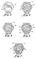
- Figure 4 is a cross-sectional view of the radial distribution valve assembly of Figure 1, taken at line X-X.
- Figure 5 is a cross-sectional view of the radial switching valve assembly of Figure 2, taken at line X-X.
- Figure 6 is cross-sectional view of the radial distribution valve assembly of Figure 1, taken at line Y-Y.
- Figure 7 is cross-sectional view of the radial switching valve assembly of Figure 2, taken at line Y-Y.
- Figure 8 is an exploded perspective view of a radial 6-port distribution valve assembly according to the prior art.
- Figure 9 is an exploded perspective view of a radial 6-port switching valve assembly according to the prior art.
- Figure 10 is a bottom view of the radial valve assemblies of Figure 8 and Figure 9.
- Figure 11 is a cross-sectional view of the radial distribution valve assembly of Figure 8, taken at line X-X.
- Figure 12 is a cross-sectional view of the radial distribution valve assembly of Figure 8, taken at line Y-Y.
- Figure 13 is a cross-sectional view of the radial switching valve assembly of Figure 9, taken at line X-X.
- Figure 14 is an exploded perspective view of an axial 6-port valve assembly according to the prior art.
- Figure 15 is a top view of the axial valve assembly of Figure 14.
- Figure 16 is a bottom view of the axial valve assembly of Figure 14.
- Figure 17 is a top view of the plug end face of an axial 6-port distribution valve assembly according to the prior art.
- Figure 18 is a top view of the plug end face of an axial 6-port switching valve assembly according to the prior art.
- Figure 19 is a diagrammatical representation of a radial stream selection valve assembly according to the prior art.
- Figure 20 is a radial, 6-port valve assembly according to the present invention.
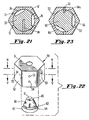
- Figure 21 is a cross-sectional view of the radial valve assembly of Figure 20, taken at line Y-Y.
- Figure 22 is a radial, 6-port valve assembly according to the present invention.
- Figure 23 is a cross-sectional view of the radial valve assembly of Figure 22, taken at line X-X.
- Figure 24 is an axial, 6-port valve assembly according to the present invention.
- Figure 25 is a top view of the plug end face of the axial valve assembly of Figure 24.
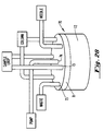
- Figure 26 depicts a flow system according to the present invention, comprising an axial 4-port valve assembly.
- Figure 27 shows possible plug orientations for a flow system corresponding to the system depicted in Figure 26, comprising a radial 4-port valve assembly in place of the axial 4-port valve assembly.
- Figure 28 depicts a flow system according to the present invention, comprising an axial 6-port valve assembly.
- Figure 29 shows possible plug orientations for a flow system corresponding to the system depicted in Figure 28, comprising a radial 6-port valve assembly in place of the axial 6-port valve assembly.
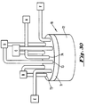
- Figure 30 depicts a flow system according to the present invention, comprising an axial 8-port valve assembly.
- Figure 31 and 32 show possible plug orientations for a flow system corresponding to the system depicted in Figure 30, comprising a radial 8-port valve assembly in place of the axial 8-port assembly.
- valve assemblies are depicted in Figures 20, 22, and 24.
- the valve assemblies of Figures 20 and 24 are particularly preferred.
- the valve assemblies comprise a housing (10, 50, or 70), which preferably comprises a peripheral face (12, 52, or 72) attached to an outer face (11, 51, or 71).
- Housings can be fabricated from a wide variety of materials. It is preferred that housings comprise stainless steel and/or an organic polymer which is inert to the fluids regulated by the valve.
- Exemplary inert polymers are aramid polymers, acetal resins, and poly(tetrafluoroethylene) -- such as available from the DuPont Company (Wilmington, DE) under the tradenames Kevlar, Delrin, and Teflon, respectively -- and poly(chlorotrifluoroethylene), such as available from the 3M Company (Newark, NJ) under the tradename Kel-F. Poly(tetrafluoroethylene) and poly(chlorotrifluoroethylene) are preferred inert polymers.
- the housing preferably comprises a common port (14, 54, or 74) and peripheral ports (13, 53, or 73).
- a common port is a port capable of fluid communication with each other port of the valve assembly, depending upon the orientation of the valve plug.
- Common ports preferably occupy a central location on the housing and, in turn, on the valve assembly.
- Peripheral ports are those ports other than the common port.
- the peripheral ports are equally-spaced about the common port at the periphery of the housing. The common and peripheral ports are thus contained in the peripheral face and/or the outer face.
- the housings of this invention comprise n peripheral ports, where n is an even integer greater than or equal to 4.
- n is 4, 6, 8, 10, or 12. More preferably, n is 4, 6, or 8. Even more preferred are housings wherein n is 6.
- Valve assemblies wherein the housing comprises 6 peripheral ports are known as 6-port valves or 6-port valve assemblies.
- valve plugs Contained within the housing and in close physical contact therewith is a circular valve plug (20, 60, or 80) having a body (22, 62, or 88) which has an end face (21, 61, or 86) and a lateral face (23, 63, or 87).
- Valve plugs can be fabricated from a wide variety of materials. Preferred valve plugs comprise an organic polymer which is inert to the fluids regulated by the valve, as set forth above.
- the valve plugs of this invention comprise a distribution channel (24, 64, or 82) and (n/2)-1 switching channels (26, 66, or 84).
- suitable channels for regulating fluid flow can have a wide variety of shapes and configurations. It is preferred that channels be configured such that there exists no axial plane of symmetry passing through the end face of the valve plug. It will be appreciated that such an asymmetric channel configuration avoids flow path duplication.
- Preferred valve plugs comprise circular, pore-like channels within the body of the valve plug, semi-circular or square grooved channels on the end face or lateral face of the valve plug, or combinations thereof.
- the channels can be created by any of the mechanical and/or chemical methods known in the art, such as etching, drilling, molding, or stamping.
- the valve assemblies of the present invention are preferably one component in systems for the regulation of fluid flow.
- the flow systems preferably comprise a terminal component in fluid communication with the valve assembly.
- a terminal component is any apparatus or device connected by tubing, piping, or other suitable means to the valve assembly by a single peripheral port of the valve assembly.
- fluid pumps, needles, canulas, detectors, tubing, sorbent columns, solid phase support resins, filters, sample loops, and waste drains provide examples of terminal components.
- Preferred flow systems further comprise a flow-through component.
- Flow-through components include any apparatus or device connected by tubing, piping, or other suitable means to the valve assembly by more than one peripheral port of the valve assembly.
- Tubing, sorbent columns, solid phase support resins, filters, sample loops, detectors, sample injection valves, and valving flow systems provide examples of flow-through components.
- Valve assemblies according to the present invention preferably meet the following criteria. They should be in a flow-allowed position when the distribution channel of the valve plug is aligned with any of the peripheral ports. They should contain exactly three port connections to terminal components of the flow system. They are preferably connected with at least one terminal component in a manner which allows flow either into or out of a channel aligned with the terminal component.
- a terminal component is connected to the common port of the distribution channel of the valve.
- the valve assembly should also contain n-2 port connections to flow-through components of a flow system. Each flow-through component should be connected at two ports of the valve to provide a flow path between these two ports. The number of flow-through components is therefore (n/2)-1. Additionally, the two ports connected to a flow-through component preferably are not adjacent one another.
- a flow system containing a valve assembly which meets these criteria will have at least one configuration of components having all of the following beneficial characteristics.
- the configuration will allow n unique flow paths which each join exactly two of the terminal components.
- a flow path is considered to be the path which includes the ports, channels and flow-through components which are in fluid communication with the two terminal components when the valve assembly is positioned in a flow-allowed orientation.
- the number of flow-through components included in a given flow path will range from zero to the maximum number of flow-through components. Exactly two flow paths will directly connect terminal components with no intervening flow-through components.
- two flow paths will include all flow-through components.
- the order of the flow-through components in the two flow paths will be reversed with respect to the terminal component connected to the common port. Further, the terminal component connected to a peripheral port will be different in each of these flow paths.
- Figure 29 illustrates a valve configuration for a 6-port valve with three terminal components -- the pump (102), needle (104 or 105) and waste (106) positions -- and two flow-through components -- a sample loop (108) and sorbent column (110).
- This valve configuration is an example which exhibits the characteristics stated above.
- Figure 27 and Figures 31 and 32 display 4-port and 8-port valves respectively configured according to the above rules. The set of unique flow paths for each configuration are displayed to the right of each flow-allowed orientation of the valve.
- valve flow systems of the present invention include the reduction of external connections between valves by use of a single valve for flow path selection. External connections undesirably increase the volume of the flow system. Another advantage is that flow paths not connected to the distribution channel are dead-ended to prevent uncontrolled flow.
- a further advantage of the present invention is that multiple valves need not be coordinated and monitored as with prior art systems. This results from all paths being switched simultaneously by a single turn of the valve plug. Also, considerable cost savings and lowered reliability concerns are recognized by reduction of the number of valves and actuators necessary to achieve multiple flow paths. Fewer valves also reduces the complexity of a flow system, which is desirable for automation of the stream selection procedure.
- a syringe pump is a common analytical instrument which is capable of aspirating and dispensing fluids. Syringe pumps are therefore useful for diluting samples, adding measured amounts of chemical reagents, transferring bulk quantities of reagent to small containers, or transferring fluids between two small containers.
- aspiration is commonly performed by providing a transfer line between the pump and needle.
- the transfer line preferably has sufficient volume to contain the aspirate, thus avoiding contamination of the syringe in the pump.
- the needle typically is lowered into the solution to be sampled and the syringe pump is drawn back to draw the solution into the sample loop.
- the aspirate may then be transferred to a second container by replacing the original solution container with a different container beneath the needle.
- a more desirable process would transfer the sample from the loop to a container positioned beneath a second needle.
- the advantage of such a process is that fewer container movements would be necessary to effect the transfer.
- a conflict occurs between the need for a minimum-volume transfer line for dispensing and the need for large volume transfer line for aspirating.
- Figure 27 demonstrates a 4-port flow configuration employing the present invention.
- the four diagrams display the flow patterns available at each of the four unique positions of the valve.
- Figures 27a and 27c demonstrate configurations suitable for minimum volume dispensing to needle (104) and needle (105), respectively.
- Figures 27b and 27d demonstrate configurations suitable for aspiration.
- the four flow paths of Figure 27 provide significantly enhanced performance of the dispenser/aspirator functions of the pump (102).
- the paths provide for the two independent functions of low-volume dispensing and aspiration under optimum conditions.
- these functions can be duplicated at two different needles (104 and 105) which may be remote from one another.
- the two needles share the same sample loop, transfers of fluid between the needles is possible without contamination of the syringe. While each of these functions is individually available by means of valve arrangements according to the prior art, no single prior art valve configuration provides all four flow patterns in a 4-port valve.
- SPE solid phase extraction
- Figure 29a demonstrates a direct connection between the pump (102) and the needle (104). This path would be used in dispensing small volumes of reagent accurately, or in washing the needle.
- Figure 29b shows a path which connects the pump (102) to the needle (104) through a sample loop (108). This path is used for aspiration of samples from vials into the sample loop for later transfer to either the SPE cartridge or another vial.
- the path shown in Figure 29c allows flow from the pump (102) through the sample loop (108), through an SPE column (110), and then to the needle (104). This path is used for applying a sample stored in the sample loop onto the SPE column.
- the path shown in Figure 29d bypasses the sample loop (108) and flows directly from the pump (102) through the column (110) to the needle (104).
- This path solves the problem of the long lead volume between the pump and the column. Column conditioning, washing, and elution of the analyte would be done by this path. Also, this path eliminates the need to load the sample only after the column is conditioned, since sample may be stored in the sample loop while other functions are occurring.
- Figure 29e shows a path which flows from the pump (102) to waste (106). This path allows for changing solvents in the syringe without having to remove vials from under the needle (104). Note that the position referred to as "waste” could also be a needle on a remote dispenser.
- the path shown in Figure 29f flows from the pump (102) in the reverse direction through the column (110), through the sample loop (108), and then to waste (106). This path allows backflushing of the column into the sample loop. Backflushing allows the sample to be removed from the column with a minimum amount of solvent. Setting the path to the sample loop allows the fraction to be retained either for delivery to a vial or to a second SPE column for multiple column extraction methods. This permits multi-column extractions without the need for an intermediate vial.
- a pump In analyzing the flow patterns in Figure 29, a pump should always be connected to the common port to achieve the six illustrated configurations. Also, it is desirable to prevent uncontrolled flow to the components by closing all flow paths which are not connected to the pump. These requirements appear to suggest that the valve must have properties of distribution valve having at least 6 peripheral ports. However, further examination indicates that the flow patterns must be more than just point-to-point connections, since four items (SPE column (110), sample loop (108). needle (104), and waste (106)) must be connected in six different combinations. Such connectivity is one property of a selection valve.
- valve assembly shown in Figure 29 is a hybrid of prior art switching and distribution valves.
- This valve has six unique flow orientations. Each orientation consists of the distribution channel connecting the common axial port to one peripheral port. Two pairs of peripheral ports are connected internally by the remaining channels and the final peripheral port is sealed against flow.
- a flow system such as shown in Figure 29 offers a number of advantages.
- the system achieves bidirectional positive hydraulic displacement flow through the column bed.
- the column (110) may be backflushed to elute sample in the minimum volume, such as shown in Figures 29c, 29d, and 29f.
- a further advantage is the provision of a low volume elution path to needle (104), such as shown in Figure 29d, wherein both flow rate and elution volume are better controlled.
- sample loop loading shown in Figure 29b
- column conditioning which is shown in Figure 29d. That is, a column (110) may be conditioned while sample is already in the loop (108).
- the flow system additionally has a low volume dispensing path, shown in Figure 29a, which reduces the amount of rinsing required. This is desirable for expensive reagents.
- the high volume aspiration path shown in Figure 29b protects the syringe.
- Figure 29 demonstrates the six flow paths available to a 6-port valve assembly according to the present invention. If the sample loop (108) and the needle (104) in this figure are respectively replaced by a second column and a detector, the resulting flow system is suitable to serve as an HPLC flow system having automated purge and column switching path selection. The choice of flow paths provides a user the choice of configuring the system for constant use or for switching between flow paths without disconnecting components.
- At least one of the flow paths shown in Figure 29 also connects directly to waste (106). This is important, since HPLC pumps generally must be primed to flow paths with very low back pressure. The introduction of bubbles into the pump head may require re-priming during normal operation, which would normally require manual disconnection of one of the components or the addition of valves to allow this low back pressure path.
- Figures 31 and 32 demonstrate an 8-port valve according to the present invention.
- three terminal components -- A, E, and F -- as well as three flow-through components -- B, C, and D -- are configured into the flow system.
- the resulting flow paths demonstrate the variety of combinations in which the components may be ordered in the flow system.
Landscapes
- Engineering & Computer Science (AREA)
- General Engineering & Computer Science (AREA)
- Mechanical Engineering (AREA)
- General Health & Medical Sciences (AREA)
- Analytical Chemistry (AREA)
- Biochemistry (AREA)
- Physics & Mathematics (AREA)
- General Physics & Mathematics (AREA)
- Immunology (AREA)
- Pathology (AREA)
- Chemical & Material Sciences (AREA)
- Life Sciences & Earth Sciences (AREA)
- Health & Medical Sciences (AREA)
- Multiple-Way Valves (AREA)
Claims (10)
- Ensemble de vanne comportant :un boítier (10, 50, ou 70) comportant un orifice commun (14, 54, ou 74) et n orifices périphériques (13, 53, ou 73), dans lequel n est un nombre entier au moins égal à 4 ; et un bouchon de vanne (20, 60, ou 80) positionné pour tourner dans le boítier, comportant :un canal de distribution (24, 64, ou 84) capable d'être en communication hydraulique avec l'orifice commun (14, 54, ou 74) et un orifice quelconque parmi les orifices périphériques (13, 53, ou 73) à un moment lors de la rotation du bouchon de vanne (20, 60, ou 80) ; et(n/2) - 1 canaux de commutation (26, 66, 84), lesdits canaux de commutation étant capables d'établir des trajets de fluide simultanés, chacun reliant au moins deux des orifices périphériques (13, 53, ou 73) lors de la rotation du bouchon de vanne (20, 60, ou 80).
- Ensemble de vanne selon la revendication 1, dans lequel n est au moins égal à 4 et pas plus grand que 8.
- Ensemble de vanne selon la revendication 1 ou 2, dans lequel le boítier (10, 50, ou 70) comporte une face extérieure (11, 51, ou 71) et une face périphérique (12, 52, ou 72) et le bouchon de vanne (20, 60, ou 80) comporte une face d'extrémité (21, 61, ou 86) et une face latérale (23, 63, ou 87).
- Ensemble de vanne selon la revendication 3, dans lequel la face extérieure (71) comporte au moins un orifice périphérique (73) et la face d'extrémité (86) comporte au moins un canal de commutation (84).
- Ensemble de vanne selon la revendication 3, dans lequel la face extérieure (11 ou 71) comporte l'orifice commun (14 ou 74) et la face d'extrémité (21 ou 86) comporte le canal de distribution (24 ou 84).
- Ensemble de vanne selon la revendication 3 ou 4, dans lequel la face périphérique (12 ou 52) comporte au moins un orifice périphérique (13 ou 53) et la face latérale (23 ou 63) comporte au moins un canal de commutation (26 ou 66).
- Ensemble de vanne selon la revendication 3, dans lequel la face périphérique (52) comporte l'orifice commun (54) et la face latérale (63) comporte le canal de distribution (64).
- Ensemble de vanne selon l'une quelconque des revendications 1 à 7, dans lequel le boítier (10, 50, ou 70), le bouchon de vanne (20, 60, ou 80), ou à la fois le boítier et le bouchon de vanne sont fabriqués à partir de polytétrafluoroéthylène ou de polychlorotrifluoroéthylène.
- Système de régulation d'écoulement de fluide comportant :au moins un composant terminal (par exemple, 106) ;un ensemble de vanne en communication de fluide avec le composant terminal comportant les caractéristiques selon l'une quelconque des revendications précédentes ; etau moins un composant à écoulement traversant (par exemple 108), en communication hydraulique avec l'ensemble de vanne.
- Ensemble de vanne selon l'une quelconque des revendications 1 à 8, dans lequel lesdits canaux sont configurés de telle sorte qu'il n'existe aucun plan axial de symétrie passant à travers la face d'extrémité du bouchon de vanne.
Applications Claiming Priority (2)
| Application Number | Priority Date | Filing Date | Title |
|---|---|---|---|
| US07/599,330 US5105851A (en) | 1990-10-17 | 1990-10-17 | Apparatus for multi-path flow regulation |
| US599330 | 1990-10-17 |
Publications (3)
| Publication Number | Publication Date |
|---|---|
| EP0481285A2 EP0481285A2 (fr) | 1992-04-22 |
| EP0481285A3 EP0481285A3 (en) | 1992-08-12 |
| EP0481285B1 true EP0481285B1 (fr) | 1998-05-20 |
Family
ID=24399196
Family Applications (1)
| Application Number | Title | Priority Date | Filing Date |
|---|---|---|---|
| EP91116791A Expired - Lifetime EP0481285B1 (fr) | 1990-10-17 | 1991-10-01 | Dispositif de réglage du débit à voies multiples |
Country Status (4)
| Country | Link |
|---|---|
| US (1) | US5105851A (fr) |
| EP (1) | EP0481285B1 (fr) |
| JP (1) | JPH05118452A (fr) |
| DE (1) | DE69129435T2 (fr) |
Families Citing this family (66)
| Publication number | Priority date | Publication date | Assignee | Title |
|---|---|---|---|---|
| US5419419A (en) * | 1989-05-26 | 1995-05-30 | Macpherson; Roger | Shifting system for positive variable drive transmisison |
| FR2672513B1 (fr) * | 1991-02-13 | 1994-03-18 | Tech Sep | Procede et module perfectionnes de filtration en milieu liquide sous flux tangentiel instationnaire. |
| US5294405A (en) * | 1992-04-09 | 1994-03-15 | Drummond Scientific Company | Adjustable valve for pipette gun |
| US5496741A (en) * | 1994-04-14 | 1996-03-05 | University Of Waterloo | Device and process for increasing analyte concentration in a sorbent |
| USD373622S (en) | 1994-06-14 | 1996-09-10 | Burden Billy G | Plumbing cap lock |
| US5584327A (en) * | 1994-07-06 | 1996-12-17 | Ecolab Inc. | Method and apparatus for storing and dispensing chemical solutions |
| US5746831A (en) * | 1994-07-12 | 1998-05-05 | Ransburg Corporation | Voltage block |
| US5575311A (en) * | 1995-01-13 | 1996-11-19 | Furon Company | Three-way poppet valve apparatus |
| US5567868A (en) * | 1995-01-23 | 1996-10-22 | Hewlett-Packard Company | Planar manifold assembly |
| US5633168A (en) * | 1995-06-07 | 1997-05-27 | Glasscock; Larry M. | Controlled dispersion flow analysis system |
| US5601405A (en) * | 1995-08-14 | 1997-02-11 | Coates; George J. | Valve apparatus for steam turbines |
| US5957152A (en) * | 1996-09-24 | 1999-09-28 | Hydro Systems Company | Select valve purge |
| US6098646A (en) * | 1997-02-19 | 2000-08-08 | Ecolab Inc. | Dispensing system with multi-port valve for distributing use dilution to a plurality of utilization points and position sensor for use thereon |
| US6012487A (en) * | 1997-03-10 | 2000-01-11 | Brian A. Hauck | Prime purge injection valve or multi-route selections valve |
| US6135153A (en) * | 1998-01-02 | 2000-10-24 | Cleland, Sr. John | Anesthesia delivery systems and methods |
| US6161583A (en) * | 1999-06-04 | 2000-12-19 | Morris; Edward J. | Control valve |
| WO2002012878A1 (fr) * | 2000-08-07 | 2002-02-14 | Doebelin Werner | Vanne clhp |
| US6374684B1 (en) * | 2000-08-25 | 2002-04-23 | Cepheid | Fluid control and processing system |
| US8048386B2 (en) | 2002-02-25 | 2011-11-01 | Cepheid | Fluid processing and control |
| US7063302B2 (en) * | 2001-03-13 | 2006-06-20 | Siemens Energy & Automation, Inc. | Sample valve with integral sample shut off function for chromatograph |
| US6655401B2 (en) | 2001-09-25 | 2003-12-02 | Hydro Systems Company | Multiple chemical product eductive dispenser |
| JP4644997B2 (ja) * | 2001-09-27 | 2011-03-09 | 株式会社島津製作所 | 送液ポンプシステム |
| US6672336B2 (en) | 2001-11-28 | 2004-01-06 | Rheodyne, Lp | Dual random access, three-way rotary valve apparatus |
| US20030175443A1 (en) * | 2002-03-14 | 2003-09-18 | Ghaffar Kazkaz | Method and apparatus for dispensing coating materials |
| US6904936B2 (en) * | 2002-04-19 | 2005-06-14 | Archidex | Flow-diverting rotary valves of multiple paths |
| DE10222334A1 (de) * | 2002-05-18 | 2003-12-04 | Leica Microsystems | Vorrichtung zum Einbringen einer Probe in ein Durchfluss-Analysensystem |
| DE10228917A1 (de) * | 2002-06-24 | 2004-01-22 | Epigenomics Ag | Vorrichtung zur Handhabung von Flüssigkeiten in einer Mehrzahl von Kanälen |
| US7032605B1 (en) | 2003-10-15 | 2006-04-25 | Douglas B. Dority | Dual piston rotary valve |
| WO2005089124A2 (fr) * | 2004-03-05 | 2005-09-29 | Waters Investments Limited | Robinet d'injection et d'isolement d'ecoulements continus combines pour fluides haute pression |
| US20050241703A1 (en) * | 2004-04-28 | 2005-11-03 | Hach Company | Single piece, multi-port precision valve |
| US7407815B2 (en) * | 2005-09-28 | 2008-08-05 | Kent State University | Liquid crystal cassette |
| US7975721B2 (en) * | 2006-03-30 | 2011-07-12 | John Hiebert | Fluid valve systems |
| JP4913470B2 (ja) * | 2006-04-26 | 2012-04-11 | 株式会社島津製作所 | 流路切換えバルブを用いた高速液体クロマトグラフ及び分析方法 |
| US8033295B2 (en) * | 2007-02-08 | 2011-10-11 | Praxair Technology, Inc. | Multi-output valve useful to promote non-stationary flame |
| US7521248B2 (en) * | 2007-04-20 | 2009-04-21 | Atherotech, Inc. | Apo B measurement system and method |
| US7870870B2 (en) * | 2007-08-20 | 2011-01-18 | Uop Llc | Multiport vertical axial valve with sealing rotor |
| DE102008006266B4 (de) | 2008-01-25 | 2011-06-09 | Dionex Softron Gmbh | Probengeber für die Flüssigkeitschromatographie, insbesondere für die Hochleistungsflüssigkeitschromatographie |
| US20100000619A1 (en) * | 2008-07-01 | 2010-01-07 | David Bryan Larson | Slurry valve |
| GB0815670D0 (en) * | 2008-08-28 | 2008-10-08 | Nuclear Decommissioning Authority | fluid flow routing |
| US8770226B2 (en) | 2008-11-13 | 2014-07-08 | Ge Healthcare Bio-Sciences Ab | Random access rotary valve |
| WO2010083147A1 (fr) | 2009-01-14 | 2010-07-22 | Waters Technologies Corporation | Soupape rotative |
| DE102009005874A1 (de) * | 2009-01-21 | 2010-07-22 | Thinxxs Microtechnology Ag | Ventil, insbesondere für ein Bauelement der Mikrofluidtechnik |
| DE102009008194B4 (de) * | 2009-02-02 | 2011-07-28 | Hansgrohe AG, 77761 | Sanitäres Abschalt- beziehungsweise Umschaltventil |
| WO2010115192A2 (fr) * | 2009-04-03 | 2010-10-07 | Integrated Nano-Technologies, Inc. | Soupape rotative à plusieurs chambres |
| US9347086B2 (en) * | 2009-04-03 | 2016-05-24 | Integrated Nano-Technologies, Llc | Method and system for sample preparation |
| CN102460145B (zh) | 2009-06-03 | 2015-04-29 | 安捷伦科技有限公司 | 使中间阀状态的压力差平衡的计量装置的样品注射器 |
| US9371921B2 (en) * | 2009-06-23 | 2016-06-21 | Nordson Corporation | Multi-port valve |
| DE102009027352A1 (de) * | 2009-06-30 | 2011-01-05 | Qiagen Gmbh | Mikroventildichtung |
| DE202009013236U1 (de) * | 2009-10-01 | 2011-02-17 | Robert Bosch Gmbh | Heizungs- und/oder Warmwasserbereitungssystem |
| JP5763644B2 (ja) * | 2010-06-25 | 2015-08-12 | コリア ユニバーシティ リサーチ アンド ビジネス ファウンデーションKorea University Research And Business Foundation | 多機能選択具、それを含む多機能全自動液体クロマトグラフィー装置及びそれを利用した試料分析方法 |
| FR2965621B1 (fr) * | 2010-10-01 | 2013-04-19 | S Seres Environnement Sa | Selecteur rotatif pour analyse en continu de plusieurs fluides. |
| KR101180309B1 (ko) * | 2012-03-27 | 2012-09-06 | (주)서일퍼시픽 | 방향 전환 밸브 유닛 및 이를 이용한 기침 보조 장치 |
| PL401491A1 (pl) * | 2012-11-07 | 2014-05-12 | Scope Fluidics Spółka Z Ograniczoną Odpowiedzialnością | Mikrokuwetka do oznaczeń biochemicznych |
| US9146182B1 (en) * | 2013-02-01 | 2015-09-29 | Elemental Scientific, Inc. | Injection valve |
| US9541207B1 (en) * | 2014-02-03 | 2017-01-10 | Elemental Scientific, Inc. | Valve assembly with bottom bypass ports |
| ES2459841B1 (es) * | 2014-03-17 | 2014-12-09 | Aurep Dos, S.L. | Dispositivo de medición del caudal de un fluido incompresible con medio impulsor |
| DE202016100451U1 (de) | 2015-06-25 | 2016-02-16 | Dionex Softron Gmbh | Probengeber für die Flüssigkeitschromatographie, insbesondere für die Hochleistungsflüssigkeitschromatographie |
| US11143633B2 (en) * | 2015-10-20 | 2021-10-12 | Waters Technologies Corporation | Systems, methods and devices for decreasing solubility problems in chromatography |
| JP7131833B2 (ja) | 2016-05-17 | 2022-09-06 | インテグレーテッド ナノ-テクノロジーズ,インコーポレイティド | 診断アッセイシステムのための濾過カラムアセンブリ |
| US11419348B2 (en) * | 2016-06-04 | 2022-08-23 | Lingyu Dong | System and method for automatically cleaning and washing ice cream or yogurt machine |
| US11441978B1 (en) * | 2018-04-12 | 2022-09-13 | Elemental Scientific, Inc. | Automatic evaporative sample preparation |
| WO2020033850A1 (fr) * | 2018-08-10 | 2020-02-13 | Nathan Saetveit | Préconcentration d'échantillons de fluide avec introduction alternée dans une double boucle |
| CN109374798B (zh) * | 2018-10-16 | 2020-11-03 | 安徽皖仪科技股份有限公司 | 多管组合式进样阀及其使用方法 |
| EP4517089A3 (fr) | 2019-11-27 | 2025-05-28 | Waters Technologies Corporation | Valve de dosage à gradient |
| US12320441B1 (en) * | 2021-02-08 | 2025-06-03 | Schivo Medical Limited | Centering electronic rotary valve |
| CN118009056A (zh) * | 2022-11-09 | 2024-05-10 | 广东美芝制冷设备有限公司 | 多通道阀、热管理集成模块和车辆 |
Family Cites Families (15)
| Publication number | Priority date | Publication date | Assignee | Title |
|---|---|---|---|---|
| DE219096C (fr) * | ||||
| US2719426A (en) * | 1952-04-23 | 1955-10-04 | Gen Electric | Apparatus for measuring gas pressure in sealed vessels |
| US3223123A (en) * | 1963-05-27 | 1965-12-14 | Sun Oil Co | Multifunction valve for chromatography |
| GB1041514A (en) * | 1964-04-28 | 1966-09-07 | Distillers Co Yeast Ltd | Improvements in or relating to fluid sampling valves |
| US3368385A (en) * | 1964-10-15 | 1968-02-13 | Phillips Petroleum Co | Sample system for chromatographic analyzers |
| GB1189995A (en) * | 1966-08-09 | 1970-04-29 | Bp Chem Int Ltd | Gas Chromatography Apparatus |
| US3508582A (en) * | 1968-03-11 | 1970-04-28 | Sun Oil Co | Selective coupling apparatus |
| US3707991A (en) * | 1971-04-12 | 1973-01-02 | J Shapiro | Remote controlled valve for irrigation systems |
| FR2148849A5 (fr) * | 1971-07-30 | 1973-03-23 | Defontaine Freres Fils | |
| US3933436A (en) * | 1972-08-15 | 1976-01-20 | Nihon Denshi Kabushiki Kaisha | Automatic analyzing apparatus |
| US4506558A (en) * | 1983-03-03 | 1985-03-26 | Rheodyne Incorporated | Injector with minimal flow-interrupt transient |
| DE3313632C2 (de) * | 1983-04-15 | 1986-01-30 | Daimler-Benz Ag, 7000 Stuttgart | Leerlauf-Enddrehzahlregler für Einspritzpumpen an Brennkraftmaschinen |
| FR2545905B1 (fr) * | 1983-05-13 | 1987-11-27 | Ferracci Francois | Dispositif de mesure de caracteristiques d'un liquide, et robinet destine notamment a un tel dispositif |
| US4625569A (en) * | 1984-01-17 | 1986-12-02 | Toyo Soda Manufacturing Co., Ltd. | Liquid injection device |
| US4690179A (en) * | 1986-11-19 | 1987-09-01 | Bleth Joel J | Fluid inductor and metering device and method of use |
-
1990
- 1990-10-17 US US07/599,330 patent/US5105851A/en not_active Expired - Fee Related
-
1991
- 1991-10-01 DE DE69129435T patent/DE69129435T2/de not_active Expired - Fee Related
- 1991-10-01 EP EP91116791A patent/EP0481285B1/fr not_active Expired - Lifetime
- 1991-10-17 JP JP3298258A patent/JPH05118452A/ja active Pending
Also Published As
| Publication number | Publication date |
|---|---|
| US5105851A (en) | 1992-04-21 |
| DE69129435T2 (de) | 1999-01-07 |
| DE69129435D1 (de) | 1998-06-25 |
| EP0481285A3 (en) | 1992-08-12 |
| EP0481285A2 (fr) | 1992-04-22 |
| JPH05118452A (ja) | 1993-05-14 |
Similar Documents
| Publication | Publication Date | Title |
|---|---|---|
| EP0481285B1 (fr) | Dispositif de réglage du débit à voies multiples | |
| US6012487A (en) | Prime purge injection valve or multi-route selections valve | |
| CN101680861B (zh) | 流量分配阀 | |
| US5803117A (en) | Multi-route full sweep selection valve | |
| US3964513A (en) | Rotating sampling valve | |
| US20070134808A1 (en) | Simultaneous multi-column liquid chromatograph for direct sampling of an array of liquid samples | |
| US12000806B2 (en) | Interface module for two-dimensional liquid chromatography | |
| EP2613157A2 (fr) | Soupape de sélection de fluide | |
| EP3642613B1 (fr) | Dilution en ligne pour un système de chromatographie en phase liquide utilisant une pompe de dosage d'échantillon | |
| US3885439A (en) | Rotating sampling valve | |
| CN112180021B (zh) | 液相色谱系统 | |
| CN104903721A (zh) | I相和ii相代谢物以及母体化合物的分析 | |
| US20060083663A1 (en) | Fluid processing devices with multiple sealing mechanisms and automated methods of use thereof | |
| GB2290283A (en) | Rotary injection valve | |
| US20190212231A1 (en) | Systems and methods for solid phase extraction for chromotographic analysis | |
| CN115267036B (zh) | 使用柱反向冲洗的lc系统和方法 | |
| US7032605B1 (en) | Dual piston rotary valve | |
| US20210362153A1 (en) | Multiple sample channel device for liquid chromatography | |
| CN223500948U (zh) | 一种二维液相系统 | |
| CN107037169A (zh) | 一种带多功能切换阀的全二维高效液相色谱仪及色谱分离方法 | |
| WO2006044441A2 (fr) | Dispositifs de traitement de liquides equipes de multiples mecanismes d'etancheite, et procedes automatises d'exploitation des dispositifs | |
| CN114829926A (zh) | 利用选择性地耦合分离单元的上游和下游的采样单元的流体分离 | |
| US6452673B1 (en) | Multiple input flow cell with single fluid path | |
| KR20200101761A (ko) | 멀티 채널 피펫 및 이를 이용한 조합 화학 분석 장치 및 방법 | |
| WO1995023328A1 (fr) | Systeme de preparation et de dosage d'echantillons |
Legal Events
| Date | Code | Title | Description |
|---|---|---|---|
| PUAI | Public reference made under article 153(3) epc to a published international application that has entered the european phase |
Free format text: ORIGINAL CODE: 0009012 |
|
| AK | Designated contracting states |
Kind code of ref document: A2 Designated state(s): DE FR GB |
|
| PUAL | Search report despatched |
Free format text: ORIGINAL CODE: 0009013 |
|
| AK | Designated contracting states |
Kind code of ref document: A3 Designated state(s): DE FR GB |
|
| 17P | Request for examination filed |
Effective date: 19921210 |
|
| 17Q | First examination report despatched |
Effective date: 19960206 |
|
| GRAG | Despatch of communication of intention to grant |
Free format text: ORIGINAL CODE: EPIDOS AGRA |
|
| GRAG | Despatch of communication of intention to grant |
Free format text: ORIGINAL CODE: EPIDOS AGRA |
|
| GRAH | Despatch of communication of intention to grant a patent |
Free format text: ORIGINAL CODE: EPIDOS IGRA |
|
| GRAH | Despatch of communication of intention to grant a patent |
Free format text: ORIGINAL CODE: EPIDOS IGRA |
|
| GRAA | (expected) grant |
Free format text: ORIGINAL CODE: 0009210 |
|
| AK | Designated contracting states |
Kind code of ref document: B1 Designated state(s): DE FR GB |
|
| PG25 | Lapsed in a contracting state [announced via postgrant information from national office to epo] |
Ref country code: FR Free format text: LAPSE BECAUSE OF FAILURE TO SUBMIT A TRANSLATION OF THE DESCRIPTION OR TO PAY THE FEE WITHIN THE PRESCRIBED TIME-LIMIT Effective date: 19980520 |
|
| REF | Corresponds to: |
Ref document number: 69129435 Country of ref document: DE Date of ref document: 19980625 |
|
| EN | Fr: translation not filed | ||
| PLBE | No opposition filed within time limit |
Free format text: ORIGINAL CODE: 0009261 |
|
| STAA | Information on the status of an ep patent application or granted ep patent |
Free format text: STATUS: NO OPPOSITION FILED WITHIN TIME LIMIT |
|
| 26N | No opposition filed | ||
| REG | Reference to a national code |
Ref country code: GB Ref legal event code: 732E |
|
| REG | Reference to a national code |
Ref country code: GB Ref legal event code: 732E |
|
| PGFP | Annual fee paid to national office [announced via postgrant information from national office to epo] |
Ref country code: DE Payment date: 20010920 Year of fee payment: 11 |
|
| REG | Reference to a national code |
Ref country code: GB Ref legal event code: IF02 |
|
| PGFP | Annual fee paid to national office [announced via postgrant information from national office to epo] |
Ref country code: GB Payment date: 20020927 Year of fee payment: 12 |
|
| PG25 | Lapsed in a contracting state [announced via postgrant information from national office to epo] |
Ref country code: DE Free format text: LAPSE BECAUSE OF NON-PAYMENT OF DUE FEES Effective date: 20030501 |
|
| PG25 | Lapsed in a contracting state [announced via postgrant information from national office to epo] |
Ref country code: GB Free format text: LAPSE BECAUSE OF NON-PAYMENT OF DUE FEES Effective date: 20031001 |
|
| GBPC | Gb: european patent ceased through non-payment of renewal fee |
Effective date: 20031001 |