EP0481292A1 - Siège, disposé en une seule ou en double rangée, dans des véhicules, en particulier des autobus - Google Patents
Siège, disposé en une seule ou en double rangée, dans des véhicules, en particulier des autobus Download PDFInfo
- Publication number
- EP0481292A1 EP0481292A1 EP91116889A EP91116889A EP0481292A1 EP 0481292 A1 EP0481292 A1 EP 0481292A1 EP 91116889 A EP91116889 A EP 91116889A EP 91116889 A EP91116889 A EP 91116889A EP 0481292 A1 EP0481292 A1 EP 0481292A1
- Authority
- EP
- European Patent Office
- Prior art keywords
- seat
- axis
- rocker
- coupling
- abutment
- Prior art date
- Legal status (The legal status is an assumption and is not a legal conclusion. Google has not performed a legal analysis and makes no representation as to the accuracy of the status listed.)
- Granted
Links
- 230000008878 coupling Effects 0.000 claims abstract description 24
- 238000010168 coupling process Methods 0.000 claims abstract description 24
- 238000005859 coupling reaction Methods 0.000 claims abstract description 24
- 230000006835 compression Effects 0.000 claims description 13
- 238000007906 compression Methods 0.000 claims description 13
- 230000033001 locomotion Effects 0.000 claims description 11
- 230000000903 blocking effect Effects 0.000 claims description 3
- 238000010276 construction Methods 0.000 description 7
- 230000007246 mechanism Effects 0.000 description 5
- 230000007704 transition Effects 0.000 description 5
- 230000008901 benefit Effects 0.000 description 3
- 238000006073 displacement reaction Methods 0.000 description 2
- 230000005540 biological transmission Effects 0.000 description 1
- 230000008859 change Effects 0.000 description 1
- 238000009434 installation Methods 0.000 description 1
- 230000036316 preload Effects 0.000 description 1
- 230000000717 retained effect Effects 0.000 description 1
Images

Classifications
-
- B—PERFORMING OPERATIONS; TRANSPORTING
- B60—VEHICLES IN GENERAL
- B60N—SEATS SPECIALLY ADAPTED FOR VEHICLES; VEHICLE PASSENGER ACCOMMODATION NOT OTHERWISE PROVIDED FOR
- B60N2/00—Seats specially adapted for vehicles; Arrangement or mounting of seats in vehicles
- B60N2/24—Seats specially adapted for vehicles; Arrangement or mounting of seats in vehicles for particular purposes or particular vehicles
- B60N2/242—Bus seats
Definitions
- the invention relates to a seat which is arranged individually or in pairs in rows in vehicles, in particular in buses and the actual seat is constructed with its reclining backrest by means of links on a cross member extending transversely to the direction of the seat of a seat underframe anchored in the respective vehicle.
- a seat has become known from utility model G 90 05 157.2, in which the actual seat is seated on an approximately centrally arranged cross member which belongs to the seat base. This design was therefore chosen in order to provide a larger space for the feet for a rear seat user.
- this was only partially successful because the frame of the seat base frame and the connecting profiles to the crossmember consume space in height and also the frame of the actual seat protrudes far back and merges relatively "angularly" into the backrest structure, which for the rear seated person as is felt uncomfortable, since the angular pipe transitions question painless movement of the legs.
- Another disadvantage is that the actual seat is rigid and cannot be adjusted. Incidentally, it should be mentioned that the side view of such a seat is not particularly appealing.
- the present invention has for its object to provide a seat of the type mentioned, which offers maximum legroom for the users of rear seats, has no danger spots where you could bump, easier to sit down and comfortable in a so-called Convertible sleeping seat.
- the cross member of the seat underframe is accommodated in the front region of the seat and serves as a linkage or support base for the rearwardly projecting seat, in that the cross member is spaced apart from one another, essentially perpendicular and symmetrical to the longitudinal axis of the seat Abutment plates for intermediate elements to the seat.
- the abutment plates which are offset towards the center towards the sides of the seat, engage on a cross member formed by a tube, to which a second cross member, also displaced downwards and slightly to the rear, is assigned, which also consists of a tube is that, together with the first cross member and the abutment plates, forms the upper part of the seat underframe, which runs slightly obliquely downwards from the top and backwards, that is, seen from the side, resembles a forward-inclined support pillar aimed at the front edge of the seat.
- the arrangement of a second crossbeam initially results in a more stable construction which, despite a second tube, does not increase in weight, since in a double arrangement it is possible to save considerably on strength and material.
- the support pillar formed backwards at first has the advantage that there is no obstacle for the feet when taking a seat on the new seat, quite apart from the fact that the support pillar, which is inclined forward, looks good. It is understood that the inclination of this support pillar is chosen so that it does not hinder the seating of the rear seat users.
- the tubes are used as a displacement abutment for the aisle-side seats of a pair of seats, i.e. in the case of an aisle-side seat, e.g. in an omnibus, it is expedient if the abutment plates are in a fixed connection with sleeves which can be displaced and locked on the cross members. Whether you make the sleeves slidable via plastic bushings or balls or in some other way is a question of construction or economic effort. In any case, it must be guaranteed that the shifting is possible without great effort and that rattling noises need not be feared.
- a particularly essential feature of the invention is the fact that an intermediate element between the abutment plates and the seat of a downwardly open U-shaped first rocker is formed, which is part of the actual seat itself or an additional part fastened to the underside of the seat, the front end of which rotatably engages an axis A of the abutment plates and the free end of the rocker is rotatable about an axis B.
- the guide gear created by the axes A, B, C and D it is possible to change the actual seat, for example by 10 ° and the backrest up to 25 in their positions, which makes it possible to create comfortable reclining opportunities without how already indicated, the large and harmless free spaces for the feet of users sitting backwards are reduced.
- the prestressed compression springs are tensioned even further when the backrest is loaded, the cushioning becomes harder or softer, depending on the position of the articulation axles, but is hardly required or rather rejected in buses, so that movement locks are provided, on which still is discussed in more detail.
- the two prestressed compression springs slide back into the starting positions of the two seat parts when the backrest has been relieved and any locking device that may be present has been released.
- the hinge axes A, B, C and D of the two wings and the coupling are arranged in such a way and cooperate with the springs or are so under the influence of stops that the axis C between the coupling and the second rocker cannot cross an imaginary straight line between the axes D and B in any phase of movement.
- the seat according to the invention can be adapted to the respective load conditions, it appears expedient that at least one of the abutments L, K arranged in pairs on the second rocker and on the coupling, preferably the abutment L on the second rocker, can be changed in position in the direction of the prestressed compression springs, by the arm pivotably engaging the second rocker and being adjustable with a screw or the like.
- a further feature of the invention is that a blocking element located between the compression springs in the form of a detachable and lockable gas spring once on the abutment plates, e.g. engages on the axis D and is rotatably articulated on the coupling at M, the coupling axes C, B, K of the coupling having different radial distances from the coupling point M in side view.
- the radial distances mentioned only play a role insofar as the movement paths of the individual axes are not obstructed.
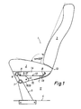
- a seat 1 which is provided for installation in vehicles, in particular in buses, essentially consists of the actual seat 2 and a backrest 3. Compared to the floor 4, the seat 1 is partially with a front covered seat base 5 supported.
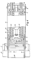
- the upper part of the seat underframe is formed by two tubes 6, 7 and two spaced-apart plates 8, 9, which, however, are offset towards the center 10 as shown results from Figure 4.
- the seat base 5 or its tube 6 is pulled far forward, that is, supports the seat 1 in the foremost region, so that the lower rear region of the seat 1 is free from annoying fastening means and large free spaces 11 for the legs of a person sitting backwards. It is equally important that the support means are not only moved forward, but also flow smoothly into the backrest 3 and so there are no sources of danger for those sitting backwards.
- the abutment plates 8, 9 serve as support means, which are designated together with 12 and which can produce both a rigid and an articulated connection to the seat 1. If one chooses a rigid connection, the picture according to FIG. 1 results, i.e., the angle ⁇ is zero degrees with respect to a horizontal and the angle a between the seat surface of the actual seat 2 and the front of the backrest 3 is approximately 100 degrees. It is not possible to adjust the inclination with respect to the horizontal. an inclination adjustment of the backrest 3 would be conceivable if e.g. a joint would be provided at 13. The large free space 11 is in no way hindered by this.
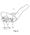
- FIG. 2 results from FIG. 2, ie an articulated support, which will be discussed in more detail below, is provided, in which not only the actual seat 2 is lowered in the rear area, but also the backrest at the same time 3 takes a different position. If one tilts the actual seat 2 by the angle ⁇ with 10 degrees in this design, there is an angle a of approximately 120 degrees between the actual seat 2 and the backrest. The smooth transition of the support means 12 into the backrest 3 is completely preserved, while the free space 11 is somewhat reduced, but only to the extent that there is no obstruction to the rear seated person. It can be clearly seen from FIGS. 1 and 2 that a normal sitting position can be converted into a reclining opportunity that falls under the term "armchair".
- the abutment plates 8, 9 are connected to the tubes 6, 7 and the support means or the intermediate elements 12 essentially consist of a first U-shaped one , downwardly open rocker 14 and a second, with its upwardly open U-shape engaging in the first rocker 14 rocker 15.
- the rocker 14 which is in the embodiment with the underside of the actual seat 2 in fixed connection, is mounted on an axis A of the two abutment plates 8, 9.
- Another bearing axis B is located at the free end of the rocker 14 and it serves as a bearing axis for a coupling 16, and this coupling 16 is connected to the second rocker 15 in a hinge-joint manner via an axis C, the rocker 15 being connected to only one in FIG Point D indicated and marked in FIG. 4 with a fastening screw 17 is connected to the abutment plates 8, 9.
- the axis C lies below an imaginary articulation line between the axes A and B and the axis C is also with its central axis slightly below an imaginary straight line between the central axes of the axes D, B.
- the rocker arm 15 has an upwardly extending boom 19, which almost fills the depth of the rocker arm 15 and in the upper region 20 has a further axis or an axle abutment L, on which two self-tensioning compression springs 21, 22 act and their second Find abutments on an axis K of the coupling 16, on both sides of the central axis 10, for which reference is made to FIG. 4.
- the arm 19 is rotatably mounted on the axis D and can be adjusted with a screw 23.
- Blocking element in the form of a gas spring 24 is provided, which lies between the compression springs 21, 22.
- This gas spring is mounted on an axis M of the coupling 16 and at the same time on the axis D. That a special construction in the region of the axis D is necessary here goes without saying, since the axis of the gas spring 24 and the axis D are not in one Allowed to cut plane. The special construction is neglected here; rather, it is illustrated in FIG. 3 how the gas spring 24 can be released and locked, with the aid of a Bowden cable 25, which is able to act on the actuating element 27 of the gas spring 24 via a lever mechanism 26 (cf. 3).
- the geometry of the seat 1 or the intermediate elements 12 is designed such that in the normal position of the seat 1 the guide gear A, B, C, D is in a kind of dead center position, ie , there is no movement when a user sits down. Movement is only possible when the locked gas spring 24 is released and the backrest 3 is loaded backwards by the user.
- the transmission is held in dynamic equilibrium by the compression springs 21, 22.
- the spring force is changed by changing the distance between the axes L, K, but the axes L and K are always pushed apart, i.e. the spring force always counteracts the forces on the backrest 3 and on the actual seat 1.
Landscapes
- Engineering & Computer Science (AREA)
- Aviation & Aerospace Engineering (AREA)
- Transportation (AREA)
- Mechanical Engineering (AREA)
- Seats For Vehicles (AREA)
- Vehicle Waterproofing, Decoration, And Sanitation Devices (AREA)
- Air-Conditioning For Vehicles (AREA)
- Passenger Equipment (AREA)
Applications Claiming Priority (4)
| Application Number | Priority Date | Filing Date | Title |
|---|---|---|---|
| DE19904031596 DE4031596A1 (de) | 1990-10-05 | 1990-10-05 | Sitz, der einzeln oder paarweise in reihen in fahrzeugen, insbesondere in omnibussen angeordnet ist |
| DE9013912U | 1990-10-05 | ||
| DE4031596 | 1990-10-05 | ||
| DE9013912U DE9013912U1 (de) | 1990-10-05 | 1990-10-05 | Sitz, der einzeln oder paarweise in Reihen in Fahrzeugen, insbesondere in Omnibussen angeordnet ist |
Publications (2)
| Publication Number | Publication Date |
|---|---|
| EP0481292A1 true EP0481292A1 (fr) | 1992-04-22 |
| EP0481292B1 EP0481292B1 (fr) | 1994-08-03 |
Family
ID=25897484
Family Applications (1)
| Application Number | Title | Priority Date | Filing Date |
|---|---|---|---|
| EP91116889A Expired - Lifetime EP0481292B1 (fr) | 1990-10-05 | 1991-10-04 | Siège, disposé en une seule ou en double rangée, dans des véhicules, en particulier des autobus |
Country Status (3)
| Country | Link |
|---|---|
| EP (1) | EP0481292B1 (fr) |
| AT (1) | ATE109409T1 (fr) |
| DE (1) | DE59102420D1 (fr) |
Cited By (3)
| Publication number | Priority date | Publication date | Assignee | Title |
|---|---|---|---|---|
| EP0627338A1 (fr) * | 1993-05-26 | 1994-12-07 | Ignaz Vogel GmbH & Co KG, Fahrzeugsitze | Siège à partie unitaire |
| WO2002040308A3 (fr) * | 2000-11-17 | 2002-10-31 | Johnson Controls Tech Co | Siege de vehicule |
| DE102017215913A1 (de) | 2017-09-08 | 2019-03-14 | Brose Fahrzeugteile Gmbh & Co. Kg, Coburg | Fahrzeugsitz mit einem um eine einzige Schwenkachse schwenkbaren Sitzteil |
Citations (5)
| Publication number | Priority date | Publication date | Assignee | Title |
|---|---|---|---|---|
| FR2326164A1 (fr) * | 1975-10-03 | 1977-04-29 | Cooper Jacques | Siege a position variable, en particulier pour vehicule ferroviaire |
| EP0229625A2 (fr) * | 1986-01-09 | 1987-07-22 | Paulisch KG | Siège pour véhicules de transport en commun |
| EP0303720A1 (fr) * | 1987-08-14 | 1989-02-22 | Grammer Ag | Siège, en particulier siège de travail, par exemple chaise de bureau ou siège de véhicule |
| EP0336852A1 (fr) * | 1988-04-08 | 1989-10-11 | Societe Industrielle Et Commerciale De Materiel Aeronautique (Sicma) Societe Anonyme | Structure de siège d'appareil de transport aérien en commun et siège comportant une telle structure |
| DE9013912U1 (de) * | 1990-10-05 | 1991-01-03 | Franz Kiel GmbH, 8860 Nördlingen | Sitz, der einzeln oder paarweise in Reihen in Fahrzeugen, insbesondere in Omnibussen angeordnet ist |
-
1991
- 1991-10-04 EP EP91116889A patent/EP0481292B1/fr not_active Expired - Lifetime
- 1991-10-04 DE DE59102420T patent/DE59102420D1/de not_active Expired - Fee Related
- 1991-10-04 AT AT91116889T patent/ATE109409T1/de not_active IP Right Cessation
Patent Citations (5)
| Publication number | Priority date | Publication date | Assignee | Title |
|---|---|---|---|---|
| FR2326164A1 (fr) * | 1975-10-03 | 1977-04-29 | Cooper Jacques | Siege a position variable, en particulier pour vehicule ferroviaire |
| EP0229625A2 (fr) * | 1986-01-09 | 1987-07-22 | Paulisch KG | Siège pour véhicules de transport en commun |
| EP0303720A1 (fr) * | 1987-08-14 | 1989-02-22 | Grammer Ag | Siège, en particulier siège de travail, par exemple chaise de bureau ou siège de véhicule |
| EP0336852A1 (fr) * | 1988-04-08 | 1989-10-11 | Societe Industrielle Et Commerciale De Materiel Aeronautique (Sicma) Societe Anonyme | Structure de siège d'appareil de transport aérien en commun et siège comportant une telle structure |
| DE9013912U1 (de) * | 1990-10-05 | 1991-01-03 | Franz Kiel GmbH, 8860 Nördlingen | Sitz, der einzeln oder paarweise in Reihen in Fahrzeugen, insbesondere in Omnibussen angeordnet ist |
Cited By (3)
| Publication number | Priority date | Publication date | Assignee | Title |
|---|---|---|---|---|
| EP0627338A1 (fr) * | 1993-05-26 | 1994-12-07 | Ignaz Vogel GmbH & Co KG, Fahrzeugsitze | Siège à partie unitaire |
| WO2002040308A3 (fr) * | 2000-11-17 | 2002-10-31 | Johnson Controls Tech Co | Siege de vehicule |
| DE102017215913A1 (de) | 2017-09-08 | 2019-03-14 | Brose Fahrzeugteile Gmbh & Co. Kg, Coburg | Fahrzeugsitz mit einem um eine einzige Schwenkachse schwenkbaren Sitzteil |
Also Published As
| Publication number | Publication date |
|---|---|
| DE59102420D1 (de) | 1994-09-08 |
| EP0481292B1 (fr) | 1994-08-03 |
| ATE109409T1 (de) | 1994-08-15 |
Similar Documents
| Publication | Publication Date | Title |
|---|---|---|
| DE69526662T2 (de) | Anordnung an einem verstellbaren stuhl | |
| EP2374371B1 (fr) | Meuble destiné à s'assoir doté d'un siège basculant dans une position d'aide à la montée en position debout | |
| DE3103188A1 (de) | Verstellbarer lehnstuhl | |
| DE4133200A1 (de) | Verstellbarer sessel | |
| DE2328399B2 (de) | Lehnstuhl | |
| EP1358821B1 (fr) | Chaise avec un accumulateur d'energie dépendant du poids d'utilisateur | |
| EP0418731A1 (fr) | Chaise | |
| DE19830418B4 (de) | Stuhlanordnung | |
| EP0827704A2 (fr) | Meuble d'assise avec siège et dossier synchronisés | |
| DE10215028A1 (de) | Sitz, insbesondere Fluggastsitz | |
| DE102019122535B4 (de) | Fahrzeugsitz | |
| AT522122B1 (de) | Sitzanordnung | |
| WO2008022704A1 (fr) | Chaise longue/fauteuil convertible | |
| DE2822574A1 (de) | Stuhl | |
| DE1919160A1 (de) | Verstellbarer Fahrzeugsitz | |
| EP4482358B1 (fr) | Accessoire fonctionnel motorisé pour sommier de lit à sommier tapissier ou de lit plateforme, ou pour sommier à lattes | |
| DE1934088A1 (de) | Verstellbarer Liegestuhl | |
| WO2001091613A1 (fr) | Chaise | |
| EP0481292B1 (fr) | Siège, disposé en une seule ou en double rangée, dans des véhicules, en particulier des autobus | |
| DE1038733B (de) | In ein Liegemoebel oder Bett verwandelbares Sitzmoebel | |
| WO1994016600A1 (fr) | Siege reglable | |
| DE69403860T2 (de) | Omnibussitz | |
| DE9013912U1 (de) | Sitz, der einzeln oder paarweise in Reihen in Fahrzeugen, insbesondere in Omnibussen angeordnet ist | |
| DE2715989A1 (de) | Sitzmoebel | |
| DE4031596A1 (de) | Sitz, der einzeln oder paarweise in reihen in fahrzeugen, insbesondere in omnibussen angeordnet ist |
Legal Events
| Date | Code | Title | Description |
|---|---|---|---|
| PUAI | Public reference made under article 153(3) epc to a published international application that has entered the european phase |
Free format text: ORIGINAL CODE: 0009012 |
|
| AK | Designated contracting states |
Kind code of ref document: A1 Designated state(s): AT BE CH DE DK ES FR GB IT LI LU NL SE |
|
| 17P | Request for examination filed |
Effective date: 19920707 |
|
| 17Q | First examination report despatched |
Effective date: 19940111 |
|
| GRAA | (expected) grant |
Free format text: ORIGINAL CODE: 0009210 |
|
| AK | Designated contracting states |
Kind code of ref document: B1 Designated state(s): AT BE CH DE DK ES FR GB IT LI LU NL SE |
|
| PG25 | Lapsed in a contracting state [announced via postgrant information from national office to epo] |
Ref country code: IT Free format text: LAPSE BECAUSE OF FAILURE TO SUBMIT A TRANSLATION OF THE DESCRIPTION OR TO PAY THE FEE WITHIN THE PRESCRIBED TIME-LIMIT;WARNING: LAPSES OF ITALIAN PATENTS WITH EFFECTIVE DATE BEFORE 2007 MAY HAVE OCCURRED AT ANY TIME BEFORE 2007. THE CORRECT EFFECTIVE DATE MAY BE DIFFERENT FROM THE ONE RECORDED. Effective date: 19940803 Ref country code: BE Effective date: 19940803 Ref country code: NL Effective date: 19940803 Ref country code: DK Effective date: 19940803 Ref country code: ES Free format text: THE PATENT HAS BEEN ANNULLED BY A DECISION OF A NATIONAL AUTHORITY Effective date: 19940803 |
|
| REF | Corresponds to: |
Ref document number: 109409 Country of ref document: AT Date of ref document: 19940815 Kind code of ref document: T |
|
| REF | Corresponds to: |
Ref document number: 59102420 Country of ref document: DE Date of ref document: 19940908 |
|
| PG25 | Lapsed in a contracting state [announced via postgrant information from national office to epo] |
Ref country code: AT Effective date: 19941004 |
|
| PG25 | Lapsed in a contracting state [announced via postgrant information from national office to epo] |
Ref country code: CH Effective date: 19941031 Ref country code: LI Effective date: 19941031 Ref country code: LU Free format text: LAPSE BECAUSE OF NON-PAYMENT OF DUE FEES Effective date: 19941031 |
|
| PG25 | Lapsed in a contracting state [announced via postgrant information from national office to epo] |
Ref country code: SE Effective date: 19941103 |
|
| ET | Fr: translation filed | ||
| GBT | Gb: translation of ep patent filed (gb section 77(6)(a)/1977) |
Effective date: 19941103 |
|
| NLV1 | Nl: lapsed or annulled due to failure to fulfill the requirements of art. 29p and 29m of the patents act | ||
| PLBE | No opposition filed within time limit |
Free format text: ORIGINAL CODE: 0009261 |
|
| STAA | Information on the status of an ep patent application or granted ep patent |
Free format text: STATUS: NO OPPOSITION FILED WITHIN TIME LIMIT |
|
| REG | Reference to a national code |
Ref country code: CH Ref legal event code: PL |
|
| 26N | No opposition filed | ||
| PGFP | Annual fee paid to national office [announced via postgrant information from national office to epo] |
Ref country code: GB Payment date: 19961004 Year of fee payment: 6 |
|
| PGFP | Annual fee paid to national office [announced via postgrant information from national office to epo] |
Ref country code: FR Payment date: 19961008 Year of fee payment: 6 |
|
| PGFP | Annual fee paid to national office [announced via postgrant information from national office to epo] |
Ref country code: DE Payment date: 19961014 Year of fee payment: 6 |
|
| PG25 | Lapsed in a contracting state [announced via postgrant information from national office to epo] |
Ref country code: GB Free format text: LAPSE BECAUSE OF NON-PAYMENT OF DUE FEES Effective date: 19971004 |
|
| PG25 | Lapsed in a contracting state [announced via postgrant information from national office to epo] |
Ref country code: FR Free format text: THE PATENT HAS BEEN ANNULLED BY A DECISION OF A NATIONAL AUTHORITY Effective date: 19971031 |
|
| GBPC | Gb: european patent ceased through non-payment of renewal fee |
Effective date: 19971004 |
|
| PG25 | Lapsed in a contracting state [announced via postgrant information from national office to epo] |
Ref country code: DE Free format text: LAPSE BECAUSE OF NON-PAYMENT OF DUE FEES Effective date: 19980701 |
|
| REG | Reference to a national code |
Ref country code: FR Ref legal event code: ST |