EP0481376B1 - Methode und Gerät zum Steuern eines eine chemische Pumpe antreibenden Schrittmotors - Google Patents
Methode und Gerät zum Steuern eines eine chemische Pumpe antreibenden Schrittmotors Download PDFInfo
- Publication number
- EP0481376B1 EP0481376B1 EP91117404A EP91117404A EP0481376B1 EP 0481376 B1 EP0481376 B1 EP 0481376B1 EP 91117404 A EP91117404 A EP 91117404A EP 91117404 A EP91117404 A EP 91117404A EP 0481376 B1 EP0481376 B1 EP 0481376B1
- Authority
- EP
- European Patent Office
- Prior art keywords
- stepping motor
- driving
- chemical pump
- current
- value
- Prior art date
- Legal status (The legal status is an assumption and is not a legal conclusion. Google has not performed a legal analysis and makes no representation as to the accuracy of the status listed.)
- Expired - Lifetime
Links
Images


Classifications
-
- H—ELECTRICITY
- H02—GENERATION; CONVERSION OR DISTRIBUTION OF ELECTRIC POWER
- H02P—CONTROL OR REGULATION OF ELECTRIC MOTORS, ELECTRIC GENERATORS OR DYNAMO-ELECTRIC CONVERTERS; CONTROLLING TRANSFORMERS, REACTORS OR CHOKE COILS
- H02P8/00—Arrangements for controlling dynamo-electric motors rotating step by step
- H02P8/12—Control or stabilisation of current
-
- A—HUMAN NECESSITIES
- A61—MEDICAL OR VETERINARY SCIENCE; HYGIENE
- A61M—DEVICES FOR INTRODUCING MEDIA INTO, OR ONTO, THE BODY; DEVICES FOR TRANSDUCING BODY MEDIA OR FOR TAKING MEDIA FROM THE BODY; DEVICES FOR PRODUCING OR ENDING SLEEP OR STUPOR
- A61M2205/00—General characteristics of the apparatus
- A61M2205/82—Internal energy supply devices
- A61M2205/8206—Internal energy supply devices battery-operated
- A61M2205/8212—Internal energy supply devices battery-operated with means or measures taken for minimising energy consumption
-
- A—HUMAN NECESSITIES
- A61—MEDICAL OR VETERINARY SCIENCE; HYGIENE
- A61M—DEVICES FOR INTRODUCING MEDIA INTO, OR ONTO, THE BODY; DEVICES FOR TRANSDUCING BODY MEDIA OR FOR TAKING MEDIA FROM THE BODY; DEVICES FOR PRODUCING OR ENDING SLEEP OR STUPOR
- A61M5/00—Devices for bringing media into the body in a subcutaneous, intra-vascular or intramuscular way; Accessories therefor, e.g. filling or cleaning devices, arm-rests
- A61M5/14—Infusion devices, e.g. infusing by gravity; Blood infusion; Accessories therefor
- A61M5/142—Pressure infusion, e.g. using pumps
- A61M5/145—Pressure infusion, e.g. using pumps using pressurised reservoirs, e.g. pressurised by means of pistons
- A61M5/1452—Pressure infusion, e.g. using pumps using pressurised reservoirs, e.g. pressurised by means of pistons pressurised by means of pistons
-
- A—HUMAN NECESSITIES
- A61—MEDICAL OR VETERINARY SCIENCE; HYGIENE
- A61M—DEVICES FOR INTRODUCING MEDIA INTO, OR ONTO, THE BODY; DEVICES FOR TRANSDUCING BODY MEDIA OR FOR TAKING MEDIA FROM THE BODY; DEVICES FOR PRODUCING OR ENDING SLEEP OR STUPOR
- A61M5/00—Devices for bringing media into the body in a subcutaneous, intra-vascular or intramuscular way; Accessories therefor, e.g. filling or cleaning devices, arm-rests
- A61M5/14—Infusion devices, e.g. infusing by gravity; Blood infusion; Accessories therefor
- A61M5/168—Means for controlling media flow to the body or for metering media to the body, e.g. drip meters, counters ; Monitoring media flow to the body
- A61M5/172—Means for controlling media flow to the body or for metering media to the body, e.g. drip meters, counters ; Monitoring media flow to the body electrical or electronic
Definitions
- the present invention relates to a control apparatus for a stepping motor used for driving a chemical pump according to the preamble part of Claim 1, more particularly, a control apparatus which is capable of controlling a chemical pump so that a driving torque of the chemical pump changes in one cycle.
- a control apparatus is known from US-A-4 444 546.
- a chemical pump for injecting chemical to a human body is required to drive a chemical injecting pump so that the chemical is allowed to be injected to a human body as a constant current.
- the inventors of the present invention know that a chemical pump normally utilizes a stepping motor and there has been proposed a control apparatus for controlling a stepping motor used for driving a chemical pump.
- a known control apparatus for controlling the stepping motor used with the chemical pump will be described in the following part.
- the known control apparatus for controlling the stepping motor used for driving a chemical pump is so arranged that the stepping motor 21 is controlled in a manner that the chemical pump (not shown) may be driven in a step-wise manner.
- a rotation of the stepping motor 21 is sensed by a photo interrupter 22 which is connected with a central processing unit (CPU) 23.
- the CPU 23 determines whether or not the stepping motor 21 loses its synchronism in accordance with a signal sensed by the photo interrupter 22.
- the CPU 23 controls the driving current for the stepping motor 21.
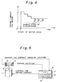
- Fig. 2 is a plot showing a characteristic of the stepping motor 21. The plot indicates that the torque generated by the stepping motor 21 is proportional to the driving current (motor current).
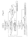
- the stepping motor 21 is started with a relatively high driving current (step T1). Then, a number of a counter n is reset to "0" (step T2). The number of the counter n indicates how often the driving current is changed. At a next step, it is checked whether or not the stepping motor 21 loses its synchronism depending on the signal sent from the photo interrupter 21 (step T3).
- step T3 In a case that a result of the above step T3 is yes, then, the driving current is a bit increased (step T4) and it is determined whether or not the increased current is larger than a predetermined value (step T5). In a case that a result of the above step T5 is no, then the process returns to the step T3. On the contrary, in a case that a result of the above step T5 is yes, then the error processing is executed.
- step T3 in a case that the stepping motor 21 does not lose its synchronism, then the number of the counter n is incremented (step T6) and it is determined whether or not the value of the number of the counter n is equal to or larger than a predetermined value N (step T7). Depending on the determined result at the step T7, in a case that the value of the number of the counter n is not equal to or larger than a predetermined value N, then the operation of the stepping motor 21 is continued. On the other hand, in a case that the value of the number of the counter n is less than the predetermined value N, then the motor current is a bit decreased (step T8), and the process is returned to the above-mentioned step T3 for further operation.
- the known control apparatus for the stepping motor actuates the stepping motor 21 with a relatively large driving current. Then, the driving current is gradually reduced N times. It results in keeping the driving current of the stepping motor 21 substantially constant. In a case that the stepping motor 21 loses its synchronism, the driving current is a bit increased so as to amend the loss of synchronism of the stepping motor 21.
- the known control apparatus for the stepping motor used for driving the chemical pump has a shortcoming that the loss of the driving current is large, because the stepping motor 21 is driven with such a substantially constant driving current so as to keep the driving torque in maximum in order to prevent the loss of synchronism of the stepping motor.
- the first object of the present invention can be achieved by an apparatus for controlling a stepping motor used for driving a chemical pump, comprising
- the storing means is a random access memory.
- the sensing means is two photo interrupters, one of the photo interrupters being capable of sensing a rotation of the stepping motor and the other one of the photo interrupters being capable of sensing a driven portion of the stepping motor.
- control means is a central processing unit.
- the divisional intervals are preferably composed of five areas, each of the five areas having a rotating angle of 72°.
- the apparatus further includes a read-only memory for storing a program for executing a control of the stepping motor by the controlling unit.
- the storage means stores a minimum current value for driving the chemical pump at each of the divisional intervals of one cycle.
- the sensing means serves to sense an angular location of the stepping motor corresponding to each cycle of the chemical pump.
- the control means serves to control the stepping motor with a minimum current value required for driving the chemical pump at the angular location following the location sensed by the sensing means.
- the driving current of the stepping motor may change depending on the driving torque of the chemical pump being fluctuated in one cycle. It results in reducing the driving current at any proper time for lowering the power consumption, thereby allowing the present control apparatus to efficiently control the stepping motor and drive the chemical pump.
- the second object of the present invention can be achieved by a method of controlling a stepping motor used for driving a chemical pump comprising a step of setting a plurality of initial values of a driving current, each of said initial value corresponding to one divisional interval r of one cycle of the chemical pump, a step of setting a number of a count n(r) for each of the divisional intervals r to be "0", the number of the count n(r) indicating how often the driving current being changed, with assuming an area number r having 1 to 5, a step of reading a current angular location of the stepping motor through an effect of a photo interrupter so as to set an area number r, a step of setting the initial value I (r) for a driving current corresponding to the area number r so as to set an actual current I, a step of detecting a rotation of the stepping motor by the photo interrupter so as to check whether the stepping motor loses a synchronism thereof, a step of increasing the driving current I(r)
- Fig. 5 is a schematic view showing an arrangement of an embodiment of the control apparatus according to the present invention.
- the control apparatus includes a stepping motor 11, a driven portion 12 of the stepping motor 11, two photo interrupters 13, 14 and a control unit 15.
- Two photo interrupters 13, 14 are located adjacent to the driven portion 12 of the stepping motor 11 (meaning that part of a chemical pump).
- a rotation of the stepping motor 11 is allowed to be sensed from the driven portion 12 by the photo interrupter 13.
- the angular location of the stepping motor 11 can be obtained by sensing the location of the driven portion 12 with the photo interrupter 14.
- the stepping motor 11 is arranged to rotate once for one operating period of the chemical pump in the following parts for better understanding of the operation of the apparatus of the present invention.
- one rotation of the stepping motor 11 is equivalent to one operating period of the chemical pump. In other words, the operation of the chemical pump at each one cycle is allowed to be sensed by the rotation of the stepping motor 11.
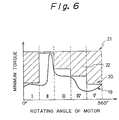
- one rotation of the stepping motor 11 is divided into five areas I to V as shown in Fig. 6.
- the control unit 15 includes a random access memory 16 for storing an initial current value required for driving the stepping motor 11 at each of the areas I to V without fail.
- the control unit 15 also includes a central processing unit 17 for controlling the driving current so as to prevent the loss of synchronism of the stepping motor 11. The control of the driving current is executed on the basis of the initial current value required for driving the stepping motor 11 at the area corresponding to the rotating location sensed by the photo interrupter 13.
- the control unit 15 further includes a read-only memory 18 and the other active elements (not shown).
- the read-only memory 18 saves a program which is executed in accordance with the steps of the processes shown in Fig. 7.
- Initial values I(1), I(2), I(3), I(4) and I(5) of the driving current are set for the areas I to V (step S1).
- a number of a count n(r) for each area is set to "0".
- the number of the count n(r) indicates how often the driving current is changed.
- a current angular location of the stepping motor 11, that is, the current driven portion 12 is read through the effect of the photo interrupter 14 and is set as an area number r (step S3).
- An initial value I(r) for a driving current corresponding to an area number r is set as an actual driving current I (step S4).
- step S5 the rotation of the stepping motor 11 is sensed by the photo interrupter 13 so as to check whether or not the stepping motor 11 loses its synchronism.
- step S5 In a case that a result of the above check at the step S5 indicates that the stepping motor 11 loses its synchronism, the operation goes to a step S6 at which the driving current I(r) is a bit increased and is set as the driving current I' (r).
- step S8 In a case that the increased driving current I' (r) is not larger than a predetermined value, the operation returns to the step S3 (step S7). On the other hand, in a case that the increased driving current I' (r) is larger than the predetermined value, the error processing is executed (step S8).
- the driving current I(r) of the stepping motor 11 is a bit reduced and is set as the driving current I'' (r), and the operation returns to the step S3 (step S11).
- the operation directly returns from the step S10 to the step S3, because it is not necessary to reduce the driving current I(r).
- step S3 the area of the driven portion 12 following the proceeding area is read by the photo interrupter 14. Then, the foregoing operation is repeated for controlling the stepping motor 11.
- the torque 19 required for the operation of the chemical pump becomes maximum in the area II where the rotating location of the stepping motor 11 ranges from 72° to 144°.
- the torque 19 required therefore is reduced in the sequence of the areas III, IV and V.
- the area III has the rotating location of the stepping motor 11 ranging from 144° to 216°
- the area IV has the rotating location of the stepping motor 11 ranging from 216° to 288°
- the area V has the rotating location of the stepping motor 11 ranging from 288° to 360°.
- Fig. 6 is a plot showing a characteristic of the driving current 20 arranged by the control apparatus for the stepping motor according to the present embodiment.
- the driving current 20 has a specific value at each of the areas I to V.
- the driving current 20 is controlled so that it becomes minimum at each of the areas I to V.
- the minimum value is represented as an initial average value changed in a step-wise manner.
- a driving current 21 represents a driving current arranged by the above-mentioned known control apparatus for a comparison, and the driving current 21 is equal to a maximum value in the area II having the rotating location ranging from 72° to 144° and is kept constant. As mentioned above, in the area II, the maximum torque is required for the operation of the chemical pump.
- the portion shown by oblique lines of Fig. 6 indicates the difference between the driving current 20 arranged by the control apparatus of this embodiment and the driving current 21 arranged by the above-mentioned known control apparatus. It will be easily understood from Fig.6 that the driving current 20 is smaller than the driving current 21.
- This portion is referred to as a driving current difference 22.
- the driving current difference 22 becomes larger, the driving current 20 is reduced as compared with the driving current 21 of the above-mentioned known control apparatus, resulting in greatly reducing the power consumption, thereby enhancing the efficiency of the stepping motor.
Landscapes
- Engineering & Computer Science (AREA)
- Power Engineering (AREA)
- Control Of Stepping Motors (AREA)
- Infusion, Injection, And Reservoir Apparatuses (AREA)
- Control Of Positive-Displacement Pumps (AREA)
Claims (7)
- Vorrichtung zum Steuern eines zum Antreiben einer chemischen Pumpe verwendeten Schrittmotors (11), mit- einer Einrichtung (16) zum Einspeichern von Anfangsstromstärken, von denen jede zum Antreiben der chemischen Pumpe in einem von mehreren Teilintervallen eines Zyklus der chemischen Pumpe erforderlich ist,- einer Einrichtung (13, 14) zum Erfassen der Drehung des Schrittmotors, um zu ermitteln, ob der Schrittmotor seine Synchronisierung verliert, wobei die Erfassungseinrichtung (13) eine Einrichtung (14) zum Erfassen des Winkelorts des Schrittmotors aufweist,- einer Einrichtung (15), die mit der Erfassungseinrichtung (13) verbunden ist, um den Schrittmotor (11) anzusteuern, wobei die Steuereinrichtung so ausgebildet ist, daß sie zunächst eine Anfangsstromstärke einstelt, wie sie dazu erforderlich ist, die chemische Pumpe anzutreiben, und sie dann die Stromstärke erhöht, wenn durch die Erfassungseinrichtung (13, 14) erkannt wird, daß der Schrittmotor seine Synchronisierung verliert,
dadurch gekennzeichnet, daß- die Teilintervalle eines Zyklus der chemischen Pumpe durch die Meßeinrichtung (14) ermittelt werden,- die Steuereinrichtung (15) mit der Meßeinrichtung (14) verbunden ist und sie den Schrittmotor (11) abhängig vom durch die Meßeinrichtung (14) erfaßten Winkelort des Schrittmotors steuert, wobei die Steuereinrichtung (15) so ausgebildet ist, daß sie den Schrittmotor in jedem der mehreren Teilintervalle dadurch steuert, daß sie die zum Antreiben der chemischen Pumpe erforderliche Anfangsstromstärke einstellt, diese Stromstärke erhöht, wenn durch die Erfassungseinrichtung erkannt wird, daß der Schrittmotor seine Synchronisierung verliert, und sie die Stromstärke bis zu einer vorgegebenen Anzahl von Malen verringert, wenn von der Erfassungseinrichtung (14) nicht erkannt wird, daß der Schrittmotor seine Synchronisierung verliert. - Vorrichtung nach Anspruch 1, bei der die Speichereinrichtung (16) ein Direktzugriffsspeicher ist.
- Vorrichtung nach Anspruch 1, bei der die Meßeinrichtung (14) eine Lichtschranke ist, die einen angetriebenen Teil der chemischen Pumpe erfassen kann.
- Vorrichtung nach Anspruch 1, bei der die Steuereinrichtung (15) eine zentrale Verarbeitungseinheit (17) ist.
- Vorrichtung nach Anspruch 1, bei der die Teilintervalle aus fünf Bereichen bestehen, von denen jeder einen Drehwinkel von 72° aufweist.
- Vorrichtung nach Anspruch 1, die ferner einen Festwertspeicher (18) zum Einspeichern eines Programms zum Ausführen einer Steuerung des Schrittmotors (11) durch die Steuereinrichtung (15) aufweist.
- Verfahren zum Steuern eines zum Antreiben einer chemischen Pumpe verwendeten Schrittmotors, das folgende Verfahren umfaßt:- Einstellen mehrerer Anfangsstärken eines zum Antreiben der chemischen Pumpe erforderlichen Stroms (S1), wobei jede der Anfangsstärken einem Teilintervall eines Zyklus der chemischen Pumpe entspricht;- Einstellen eines Zählwerts n(r) auf "0" für jedes der Teilintervalle, wobei dieser Zählwert n(r) anzeigt, wie oft der Treiberstrom geändert wird, wobei für eine Bereichszahl r angenommen ist, daß sie die Werte 1 bis 5 annimmt (S2);- Lesen des aktuellen Winkelorts des Schrittmotors mittels einer Lichtschranke, um die Bereichszahl r einzustellen (S3) ;- Einstellen des Anfangswerts I(r) des Treiberstroms entsprechend der Bereichszahl r, um den aktuellen Strom I einzustellen (S4);- Erfassen der Drehung des Schrittmotors mittels der Lichtschranke, um zu überprüfen, ob der Schrittmotor seine Synchronisierung verliert (S5);- Erhöhen des Treiberstroms I(r), wenn das Ergebnis der vorstehend genannten Prüfung anzeigt, daß der Schrittmotor seine Synchronisierung verliert, um einen erhöhten Treiberstrom I'(r) einzustellen (S6);- Inkrementieren des Zählwerts n(r) um eins, so daß n(r) = n(r)+1 gilt, wenn der Schrittmotor seine Synchronisierung nicht verliert (S7);- Ermitteln, ob der Zählwert n(r) einem vorgegebenen Wert n entspricht (S8); und- Verringern des Treiberstroms I(r) des Schrittmotors, wenn der Zählwert n(r) kleiner als der vorgegebene Wert n ist, um einen verringerten Treiberstrom I''(r) einzustellen (S9).
Applications Claiming Priority (2)
| Application Number | Priority Date | Filing Date | Title |
|---|---|---|---|
| JP2282565A JPH04156857A (ja) | 1990-10-19 | 1990-10-19 | 輸液ポンプ用ステッピングモータ制御装置 |
| JP282565/90 | 1990-10-19 |
Publications (3)
| Publication Number | Publication Date |
|---|---|
| EP0481376A2 EP0481376A2 (de) | 1992-04-22 |
| EP0481376A3 EP0481376A3 (en) | 1993-12-01 |
| EP0481376B1 true EP0481376B1 (de) | 1996-02-28 |
Family
ID=17654138
Family Applications (1)
| Application Number | Title | Priority Date | Filing Date |
|---|---|---|---|
| EP91117404A Expired - Lifetime EP0481376B1 (de) | 1990-10-19 | 1991-10-11 | Methode und Gerät zum Steuern eines eine chemische Pumpe antreibenden Schrittmotors |
Country Status (4)
| Country | Link |
|---|---|
| US (1) | US5355067A (de) |
| EP (1) | EP0481376B1 (de) |
| JP (1) | JPH04156857A (de) |
| DE (1) | DE69117421T2 (de) |
Families Citing this family (15)
| Publication number | Priority date | Publication date | Assignee | Title |
|---|---|---|---|---|
| JPH06311793A (ja) * | 1993-04-23 | 1994-11-04 | Yamaha Motor Co Ltd | ステップモータの回転制御装置 |
| DE69408055T2 (de) * | 1993-04-02 | 1998-05-07 | Yamaha Motor Co Ltd | Verfahren und Einrichtung zur Schmierung einer Brennkraftmaschine |
| US7338260B2 (en) * | 2004-03-17 | 2008-03-04 | Baxier International Inc. | System and method for controlling current provided to a stepping motor |
| JP5395184B2 (ja) * | 2009-09-26 | 2014-01-22 | Toa株式会社 | 旋回型カメラ |
| JP6087152B2 (ja) | 2010-03-16 | 2017-03-01 | サノフィ−アベンティス・ドイチュラント・ゲゼルシャフト・ミット・ベシュレンクテル・ハフツング | 注射デバイスのモータの制御方法及び制御装置 |
| US9320849B2 (en) * | 2010-09-24 | 2016-04-26 | Perqflo, Llc | Infusion pumps |
| US8915879B2 (en) | 2010-09-24 | 2014-12-23 | Perqflo, Llc | Infusion pumps |
| US8905972B2 (en) | 2010-11-20 | 2014-12-09 | Perqflo, Llc | Infusion pumps |
| US12178992B2 (en) | 2014-09-30 | 2024-12-31 | Medtronic Minimed, Inc. | Different disposable assemblies for the same reusable assembly |
| US10159786B2 (en) | 2014-09-30 | 2018-12-25 | Perqflo, Llc | Hybrid ambulatory infusion pumps |
| DE102014226727B4 (de) * | 2014-12-19 | 2025-01-30 | Vitesco Technologies GmbH | Verfahren zum Antrieb eines Lastgeräts durch einen Schrittmotor |
| EP3258989B1 (de) | 2015-02-18 | 2020-01-01 | Medtronic Minimed, Inc. | Ambulante infusionspumpe und reservoiranordnungen dafür |
| JP2018138869A (ja) * | 2015-07-02 | 2018-09-06 | 株式会社イシダ | 計量装置 |
| EP4623953A3 (de) | 2016-02-12 | 2025-11-26 | Medtronic MiniMed, Inc. | Ambulante infusionspumpe und anordnungen zur verwendung derselben |
| US11260171B2 (en) | 2017-07-04 | 2022-03-01 | Medtronic Minimed, Inc. | Ambulatory infusion pumps and assemblies for use with same |
Family Cites Families (23)
| Publication number | Priority date | Publication date | Assignee | Title |
|---|---|---|---|---|
| US3701345A (en) * | 1970-09-29 | 1972-10-31 | Medrad Inc | Angiographic injector equipment |
| US3855515A (en) * | 1972-03-06 | 1974-12-17 | Waters Associates Inc | Motor control circuit |
| US4330739A (en) * | 1980-02-07 | 1982-05-18 | Mcc Associates | Method of determining operating parameters for a stepping motor |
| US4444546A (en) * | 1980-09-19 | 1984-04-24 | Oximetrix, Inc. | Occlusion detection apparatus and method |
| DE3138267C2 (de) * | 1981-09-25 | 1985-05-30 | Pfrimmer-Viggo GmbH & Co KG, 8520 Erlangen | Vorrichtung zur enteralen Verabreichung von Nahrung |
| CA1201999A (en) * | 1982-08-03 | 1986-03-18 | Peter G. Wheeldon | Fluid flow control process and apparatus |
| JPS59123196A (ja) * | 1982-12-29 | 1984-07-16 | 松下電工株式会社 | 調光装置 |
| GB8312069D0 (en) * | 1983-05-03 | 1983-06-08 | Peritronic Medical Ind Plc | Peristaltic pumps |
| JPH0758069B2 (ja) * | 1983-09-09 | 1995-06-21 | 株式会社日立製作所 | 圧縮機のモータ制御装置 |
| EP0180083B1 (de) * | 1984-10-19 | 1990-08-22 | Kollmorgen Corporation | Regelungssysteme für variable Reluktanzmaschinen |
| US4817887A (en) * | 1985-12-13 | 1989-04-04 | Canon Kabushiki Kaisha | Device for controlling reel driving motor |
| JP2610126B2 (ja) * | 1986-07-01 | 1997-05-14 | 沖電気工業 株式会社 | プリンタにおけるラインフィード用パルスモータの制御方法 |
| JPS63181685A (ja) * | 1987-01-22 | 1988-07-26 | Toshiba Corp | 電動機の速度制御装置 |
| US4868477A (en) * | 1987-06-23 | 1989-09-19 | The Superior Electric Company | Method and apparatus for controlling torque and torque ripple in a variable reluctance motor |
| JPS6419998A (en) * | 1987-07-14 | 1989-01-24 | Star Mfg Co | Driving method for step motor |
| US4882530A (en) * | 1987-08-29 | 1989-11-21 | Nippondenso Co., Ltd. | Stepping motor control apparatus |
| JPS6480684A (en) * | 1987-09-22 | 1989-03-27 | Sumitomo Wall Systems Ltd | Handle device for sash "shoji" screen for inner falling-down opening-in |
| US4954764A (en) * | 1987-12-30 | 1990-09-04 | Samsung Electronic Co., Ltd. | Circuit and method for power efficiency improvement of induction motors |
| JPH02151298A (ja) * | 1988-11-30 | 1990-06-11 | Canon Inc | ステッピングモータ駆動装置 |
| JPH02285999A (ja) * | 1989-04-26 | 1990-11-26 | Citizen Watch Co Ltd | ステッピングモータの駆動回路 |
| JPH0332396A (ja) * | 1989-06-28 | 1991-02-12 | Sharp Corp | ステッピングモータ駆動装置 |
| US5107194A (en) * | 1989-08-14 | 1992-04-21 | Xerox Corporation | Stepper motor control to vary output torque |
| US4961038A (en) * | 1989-10-16 | 1990-10-02 | General Electric Company | Torque estimator for switched reluctance machines |
-
1990
- 1990-10-19 JP JP2282565A patent/JPH04156857A/ja active Pending
-
1991
- 1991-10-08 US US07/771,980 patent/US5355067A/en not_active Expired - Fee Related
- 1991-10-11 DE DE69117421T patent/DE69117421T2/de not_active Expired - Fee Related
- 1991-10-11 EP EP91117404A patent/EP0481376B1/de not_active Expired - Lifetime
Also Published As
| Publication number | Publication date |
|---|---|
| US5355067A (en) | 1994-10-11 |
| JPH04156857A (ja) | 1992-05-29 |
| DE69117421D1 (de) | 1996-04-04 |
| EP0481376A3 (en) | 1993-12-01 |
| DE69117421T2 (de) | 1996-09-12 |
| EP0481376A2 (de) | 1992-04-22 |
Similar Documents
| Publication | Publication Date | Title |
|---|---|---|
| EP0481376B1 (de) | Methode und Gerät zum Steuern eines eine chemische Pumpe antreibenden Schrittmotors | |
| US4684865A (en) | Method and device for controlling the acceleration of an electric stepping motor | |
| JPH0154232B2 (de) | ||
| EP0116677B1 (de) | Schrittmotorsteuerungsschaltung | |
| EP0403658A1 (de) | Geschwindigkeitsregelverfahren für einen servomotor | |
| KR100562698B1 (ko) | 증분 위치 검출을 이용한 전기 서보 모터의 트래킹 검출 방법 | |
| EP0618519A1 (de) | Verfahren zum Einstellen Rechnungskonstanten in einer Wechselrichteranordnung | |
| JPH08339212A (ja) | 産業用制御器の絶対原点復帰方法 | |
| JPH07124827A (ja) | ねじ締め装置 | |
| US6646408B2 (en) | Method for controlling operating of switched reluctance motor (SRM) | |
| JP3635674B2 (ja) | 昇降装置 | |
| US5056445A (en) | Control system for stopping sewing machine needle at predetermined position | |
| EP0131357B1 (de) | Steuergerät | |
| US4564898A (en) | Programmable controller having a drum type sequencer function subject to programming | |
| JPH04168988A (ja) | 電動機の速度制御方式 | |
| US4939664A (en) | Numerical control apparatus and method for preparing machining data for cutting an area which is narrow in the middle | |
| JP3648749B2 (ja) | トラクタの姿勢制御装置 | |
| EP0178328A1 (de) | Analogeingangssteuerungssystem | |
| KR890003291B1 (ko) | 재봉틀 제어장치 | |
| JP2963676B2 (ja) | プログラマブルコントローラ | |
| JP2553490B2 (ja) | シ−ケンス制御装置の異常検出装置 | |
| JPH0456321B2 (de) | ||
| JPH07122925A (ja) | パラボラアンテナの方向設定装置 | |
| JPH0313765Y2 (de) | ||
| KR100243079B1 (ko) | 로봇의 제어장치 및 그 제어방법 |
Legal Events
| Date | Code | Title | Description |
|---|---|---|---|
| PUAI | Public reference made under article 153(3) epc to a published international application that has entered the european phase |
Free format text: ORIGINAL CODE: 0009012 |
|
| AK | Designated contracting states |
Kind code of ref document: A2 Designated state(s): DE FR GB |
|
| PUAL | Search report despatched |
Free format text: ORIGINAL CODE: 0009013 |
|
| AK | Designated contracting states |
Kind code of ref document: A3 Designated state(s): DE FR GB |
|
| 17P | Request for examination filed |
Effective date: 19931209 |
|
| 17Q | First examination report despatched |
Effective date: 19940613 |
|
| GRAA | (expected) grant |
Free format text: ORIGINAL CODE: 0009210 |
|
| AK | Designated contracting states |
Kind code of ref document: B1 Designated state(s): DE FR GB |
|
| REF | Corresponds to: |
Ref document number: 69117421 Country of ref document: DE Date of ref document: 19960404 |
|
| ET | Fr: translation filed | ||
| PLBE | No opposition filed within time limit |
Free format text: ORIGINAL CODE: 0009261 |
|
| STAA | Information on the status of an ep patent application or granted ep patent |
Free format text: STATUS: NO OPPOSITION FILED WITHIN TIME LIMIT |
|
| 26N | No opposition filed | ||
| PGFP | Annual fee paid to national office [announced via postgrant information from national office to epo] |
Ref country code: GB Payment date: 19991006 Year of fee payment: 9 |
|
| PGFP | Annual fee paid to national office [announced via postgrant information from national office to epo] |
Ref country code: DE Payment date: 19991008 Year of fee payment: 9 |
|
| PGFP | Annual fee paid to national office [announced via postgrant information from national office to epo] |
Ref country code: FR Payment date: 19991011 Year of fee payment: 9 |
|
| PG25 | Lapsed in a contracting state [announced via postgrant information from national office to epo] |
Ref country code: GB Free format text: LAPSE BECAUSE OF NON-PAYMENT OF DUE FEES Effective date: 20001011 |
|
| GBPC | Gb: european patent ceased through non-payment of renewal fee |
Effective date: 20001011 |
|
| PG25 | Lapsed in a contracting state [announced via postgrant information from national office to epo] |
Ref country code: FR Free format text: LAPSE BECAUSE OF NON-PAYMENT OF DUE FEES Effective date: 20010629 |
|
| PG25 | Lapsed in a contracting state [announced via postgrant information from national office to epo] |
Ref country code: DE Free format text: LAPSE BECAUSE OF NON-PAYMENT OF DUE FEES Effective date: 20010703 |
|
| REG | Reference to a national code |
Ref country code: FR Ref legal event code: ST |