EP0481661B1 - Rotorblätter eines Drehflügelflugzeuges - Google Patents
Rotorblätter eines Drehflügelflugzeuges Download PDFInfo
- Publication number
- EP0481661B1 EP0481661B1 EP91309244A EP91309244A EP0481661B1 EP 0481661 B1 EP0481661 B1 EP 0481661B1 EP 91309244 A EP91309244 A EP 91309244A EP 91309244 A EP91309244 A EP 91309244A EP 0481661 B1 EP0481661 B1 EP 0481661B1
- Authority
- EP
- European Patent Office
- Prior art keywords
- blade
- rotor blade
- further characterised
- leading edge
- control vanes
- Prior art date
- Legal status (The legal status is an assumption and is not a legal conclusion. Google has not performed a legal analysis and makes no representation as to the accuracy of the status listed.)
- Expired - Lifetime
Links
- 230000008859 change Effects 0.000 claims description 8
- 239000000463 material Substances 0.000 claims description 6
- 230000001419 dependent effect Effects 0.000 claims 1
- 238000000926 separation method Methods 0.000 description 13
- 238000012360 testing method Methods 0.000 description 8
- 238000010276 construction Methods 0.000 description 5
- 230000009467 reduction Effects 0.000 description 4
- 230000003111 delayed effect Effects 0.000 description 2
- 230000000694 effects Effects 0.000 description 2
- 230000003993 interaction Effects 0.000 description 2
- 239000000203 mixture Substances 0.000 description 2
- 230000035939 shock Effects 0.000 description 2
- RZVHIXYEVGDQDX-UHFFFAOYSA-N 9,10-anthraquinone Chemical compound C1=CC=C2C(=O)C3=CC=CC=C3C(=O)C2=C1 RZVHIXYEVGDQDX-UHFFFAOYSA-N 0.000 description 1
- 241000721701 Lynx Species 0.000 description 1
- 238000013459 approach Methods 0.000 description 1
- 239000002131 composite material Substances 0.000 description 1
- 230000001627 detrimental effect Effects 0.000 description 1
- 239000012530 fluid Substances 0.000 description 1
- 230000006872 improvement Effects 0.000 description 1
- 210000003734 kidney Anatomy 0.000 description 1
- 238000004519 manufacturing process Methods 0.000 description 1
- 239000007769 metal material Substances 0.000 description 1
- 238000012986 modification Methods 0.000 description 1
- 230000004048 modification Effects 0.000 description 1
- 239000002245 particle Substances 0.000 description 1
- 230000007480 spreading Effects 0.000 description 1
- 230000001629 suppression Effects 0.000 description 1
Images


Classifications
-
- B—PERFORMING OPERATIONS; TRANSPORTING
- B64—AIRCRAFT; AVIATION; COSMONAUTICS
- B64C—AEROPLANES; HELICOPTERS
- B64C27/00—Rotorcraft; Rotors peculiar thereto
- B64C27/32—Rotors
- B64C27/46—Blades
- B64C27/463—Blade tips
-
- B—PERFORMING OPERATIONS; TRANSPORTING
- B64—AIRCRAFT; AVIATION; COSMONAUTICS
- B64C—AEROPLANES; HELICOPTERS
- B64C23/00—Influencing air flow over aircraft surfaces, not otherwise provided for
- B64C23/06—Influencing air flow over aircraft surfaces, not otherwise provided for by generating vortices
-
- Y—GENERAL TAGGING OF NEW TECHNOLOGICAL DEVELOPMENTS; GENERAL TAGGING OF CROSS-SECTIONAL TECHNOLOGIES SPANNING OVER SEVERAL SECTIONS OF THE IPC; TECHNICAL SUBJECTS COVERED BY FORMER USPC CROSS-REFERENCE ART COLLECTIONS [XRACs] AND DIGESTS
- Y02—TECHNOLOGIES OR APPLICATIONS FOR MITIGATION OR ADAPTATION AGAINST CLIMATE CHANGE
- Y02T—CLIMATE CHANGE MITIGATION TECHNOLOGIES RELATED TO TRANSPORTATION
- Y02T50/00—Aeronautics or air transport
- Y02T50/10—Drag reduction
Definitions
- This invention relates to helicopter rotor blades and is particularly concerned with rotor blades of the construction disclosed in GB-A-1538055.
- Rotor blades according to GB-A-1538055 are characterized by a swept tip portion which in plan has a forwardly swept leading edge portion, a rearwardly swept leading edge portion, a rearwardly swept extreme tip edge and a rearwardly swept trailing edge.
- Such rotor blades have proved highly successful in producing large increases in the allowable rotor operating envelope, and were a significant factor in the establishment of the world absolute speed record for helicopters of 400.81 km/hr (249.10mph) set by a Westland Lynx helicopter in 1986.
- wind tunnel tests of the prior rotor blades revealed an area of separated flow on an upper surface of the blade behind the notch region (i.e. the region where the forwardly swept leading edge portion of the tip joins the leading edge of the blade).
- the problem occurs at high angles of incidence in a range typically encountered by the retreating blade of a helicopter sustaining rotor, and the size of the separated area increases as incidence is increased.
- Prior art means for maintaining attached flow include the vortex generating devices of US-A-4655419 for fixed wing applications and US-A-4455045 for fixed wing and road vehicle applications.
- the vortex generators comprise upstanding generally planar members positioned near the maximum thickness of the aerofoil and in the latter comprise generally triangular shaped channels located at the trailing edge of a wing. Tests showed that such arrangements were unsuitable for preventing separated flow behind the notch region of a helicopter rotor blade of the construction disclosed in GB-A-1538055.
- An objective of this invention is therefore to reduce or eliminate the area of separated flow behind the notch region of a helicopter rotor blade of the construction disclosed in GB-A-1538055.
- this invention provides a rotor blade having a leading edge and a trailing edge defining a blade chord, a pitch change axis and a swept tip including a forwardly swept leading edge blended with the blade leading edge to define a notch region, wherein a plurality of rearwardly extending boundary layer control vanes protrude from an upper aerofoil surface of the rotor blade and are spaced-apart along the notch region, the control vanes comprising thin fences extending between leading and trailing edges thereof with the leading edges of at least some of the control vanes substantially coincident with said forwardly swept leading edge.
- control vanes extending from the forwardly swept leading edge are in planes generally perpendicular to said pitch change axis.
- three control vanes extend rearwardly from said forwardly swept leading edge and two additional rearwardly extending boundary layer control vanes are located inboard of said vanes extending from said forwardly swept leading edge.
- said additional control vanes are located in planes at an angle to a plane perpendicular to said pitch change axis so as to extend from their leading edges rearwardly and outwardly. The said angle may be about 5 degrees.
- the said additional control vanes are preferably staggered rearwardly and spaced-apart from said leading edge of the rotor blade.
- the leading and trailing edges of the control vanes extend generally perpendicular with respect to a local blade chord line, and said control vanes may protrude from said aerofoil surface in planes generally perpendicular to a spanwise plane through the blade chord.
- the heights of the control vanes may be between 1.5 and 2 times the thickness of the boundary layer operative on an adjacent surface of the rotor blade and may increase rearwardly from the control vane leading edge.
- the height of the control vanes extending from said forwardly swept leading edge increases from a height equivalent to about 0.22 per cent blade chord adjacent their leading edges to a height equivalent to about 0.88 per cent blade chord adjacent their trailing edges
- the height of the additional inboard control vanes increases from a height equivalent to about 0.37 per cent blade chord adjacent their leading edges to a height equivalent to about 1.47 per cent blade chord adjacent their trailing edges.
- the lengths of all of the control vanes may be substantially equal and may be between 5 and 40 per cent of the blade chord dimension. In one embodiment the lengths of the control vanes are equivalent to about 20 per cent of the blade chord dimension.
- control vanes may be attached to the blade aerofoil surface using fillets of bonding material at the blade/ control vane junction.
- the fillets Preferably have a small concave radius and a height not more than about one half the height of the respective control vane.
- a helicopter sustaining rotor blade generally indicated at 11 of the construction disclosed in GB-A-1538055 includes a swept tip 12 attached at the end of a central portion 13 of aerofoil section and having a leading edge 14 and a trailing edge 15 defining a blade chord dimension 'C'.
- pitch changes occur about a pitch change axis 38 extending longitudinally along the blade at about 25 per cent chord.
- Swept tip 12 includes a forwardly swept leading edge portion 16 blended with the leading edge 14, a curved rearwardly extending leading edge portion 17 and a swept extreme tip edge 18 blended with leading edge portion 17 by a blend radius portion 19.
- a curved rearwardly swept trailing edge 20 blends with trailing edge 15 and extends to join the end of swept tip edge 18 at point 20 a to complete the shape of the swept tip 12.
- Point 20 a defines in operation the overall length of the rotor blade 11.
- the area of the tip 12 encompassing the forwardly swept leading edge portion 16 and identified within the area 21 on Figure 1 has become known as the notch region of such rotor blades and will be so referenced in the remainder of this specification.
- Wind tunnel tests of the blade of Figure 1 as a non-rotating wing at a Reynolds Number of 0.6 x 10⁶ and intended to represent a retreating blade revealed an area of separated flow emanating forward from the trailing edge 15 behind the notch region 21 at high angles of attack or incidence.
- the area of separated flow first appeared at an incidence of about 9 degrees as a small "kidney" shaped area at the trailing edge 15.
- the area of separated flow As incidence was increased, the area of separated flow also grew, becoming more triangular in shape by spreading inboard along the trailing edge 15 while the apex moved forwardly from the trailing edge 15 along the upper aerofoil surface of the blade.
- the generally triangular shaped area of separated flow As identified at 46 in Figure 1, at an angle of incidence of 13 degrees, the generally triangular shaped area of separated flow has a base length of about 0.75C and has spread forward by a similar amount.
- the area of separated flow identified at 47 in Figure 1 actually reaches the leading edge of the blade 11 in the notch region 21 and its base has increased to a length equivalent to about 1.35C.
- boundary layer control vanes 22 located in the notch region 21 on an upper surface of the rotor blade 11, might be useful in delaying the onset of flow separation, and a preferred arrangement is illustrated in Figure 2.
- five boundary layer control vanes 22 protrude from the blade surface and are spaced-apart along the length of the notch region 21, the three outer control vanes 22 a , 22 b and 22 c extending rearwardly from a leading edge located substantially coincident with the forwardly swept leading edge 16 of the tip 12 of rotor blade 11.
- the remaining two inboard control vanes 22 d and 22 e extend rearwardly from leading edges spaced-apart slightly from the blade leading edge 15 and staggered rearwardly.
- Wind tunnel testing of the rotor blade of Figure 2 showed that the boundary layer control vanes 22 were extremely effective in suppressing the spread of flow separation and delaying stalling of the blade.
- the area 46 of separated flow is almost completely eliminated at an incidence of 13 degrees, and the area 47 of separated flow at an incidence of 15 degrees is drastically reduced from that effective on the blade of Figure 1.
- the area 47 of separated flow effective at 15 degrees incidence in the blade of Figure 2 extends forward from the blade trailing edge by an amount equal to about 0. 37C and has a base length of only about 0.62C.
- the delay in drag divergence provides a reduction in the power required by the rotor blade of this invention and the delay in pitching moment break will delay control load growth in forward flight at the retreating blade limits. Performance also is enhanced at high incidence by the delay in the loss of lift.
- Figure 10 plots lift coefficient (C L ) against profile drag coefficient (C D ) to illustrate more clearly the characteristics of a blade according to the invention at lower angles of incidence than those considered in obtaining the data from which Figures 1 and 2 derive.
- the characteristics of the blade of the invention are shown in broken line. It will be noted that at low lift the blade of the invention exhibits a small increase in profile drag. However, at a moderate lift coefficient of about 0.9 there is a useful reduction in profile drag as indicated at 44. As shown this is representative of an angle of incidence between eight and nine degrees.
- control vanes 22 protrude from on the upper aerofoil surface and are equally spaced-apart along the length of the notch region 21.
- the control vanes 22 comprise thin fences about 1mm thick extending substantially rearwardly between generally upstanding leading and trailing edges identified respectively by numerals 23 to 27 inclusive and 28 to 32 inclusive.
- the control vanes 22 a to 22 e are of substantially uniform length 33 equal to about 20 per cent C, and increase in height from the leading edges 23 to 27.
- the height of the control vanes is chosen to be slightly greater than the thickness of the boundary layer experienced on the adjacent surface of the blade during operation and, typically, will be between about 1.5 and 2 times the thickness.
- each of the three control vanes 22 a , 22 b and 22 c extending from leading edges 23, 24 and 25 coincident with the forwardly swept leading edge portion 16 have a height 34 equivalent to about 0.22 per cent C adjacent their leading edges 23 to 25 and a height 35 of about 0.88 per cent C adjacent their trailing edges 28, 29, 30.
- Each of the two inboard control vanes 22 d and 22 e have a height 36 adjacent their leading edges 26, 27 equivalent to about 0.37 per cent C and a height 37 adjacent their trailing edges 31 and 32 equivalent to about 1.47 per cent C.
- Figure 4 is typical for all three of the outboard control vanes 22 a , 22 b and 22 c and shows that the leading edges 23, 24 and 25 of those vanes extend generally perpendicular with respect to a local blade chord line from a position substantially coincident with the forwardly swept leading edge portion 16 of the notch region 21.
- the vanes 22 a , 22 b and 22 c extend rearwardly from the leading edges 23, 24 and 25 in planes generally perpendicular to a reference axis comprising pitch change axis 38, i.e. streamwise as shown in Figure 3.
- Inboard control vanes 22 d and 22 e are staggered rearwardly and extend respectively from leading edge 26 located at a distance 39 equal to about 10 per cent C from leading edge 14 of the blade ( Figure 5), and from leading edge 27 located at a distance 40 equal to about 15 per cent C from leading edge 14 ( Figure 6). Additionally, in the illustrated embodiment, the two inboard control vanes 22 d and 22 e are each located in planes at a small angle ⁇ of about 5 degrees to a plane perpendicular to the reference axis 38 as shown in Figure 3 so as to extend from the respective leading edges 26 and 27 rearwardly and outwardly.
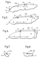
- control vanes 22 protrude from the upper aerofoil surface in planes generally perpendicular to a spanwise plane through the blade chord ( Figures 7 and 8) and are attached using fillets 41 of bonding material along the control vane/blade junction.
- the tests showed that the performance of the control vanes 22 was sensitive to the configuration of the fillets 41 and, for example, triangular fillets were found to be detrimental to performance of the control vanes.
- the trailing edges 28 to 32 inclusive of the control vanes 22 should preferably extend generally perpendicular with respect to a local blade chord line in order to provide an advantageous substantially right angle corner with the upper surfaces of the vanes 22.
- a small concave radius fillet 42 of bonding material (Figures 3, 4 and 5) is required at the base, and the edges of the fillets 42 are best removed or faired to minimise the rear facing area.
- Fillets 43 at the leading edges of control vanes 22 d and 22 e are similarly faired as are the leading edges 23, 24 and 25 of the outer three control vanes 22 a , 22 b and 22 c . This fairing of the leading and trailing edges of the control vanes 22 reduces aerodynamic drag.
- the location of the boundary layer control vanes 22 of this invention in the leading edge region of the rotor blade generates small streamwise vortices which re-energise and stabilize the boundary layer thereby suppressing or delaying the onset of flow separation at the trailing edge of the blade.
- control vanes 22 are located at or adjacent the leading edge of the rotor blade, that the three outer control vanes 22 a , 22 b and 22 c extend in planes streamwise or perpendicular to the reference axis 38 from a leading edge 23, 24 and 25 generally coincident with the forwardly swept leading edge portion 16 of notch region 21, and that the two inboard control vanes 22 d and 22 e extend in planes at a small angle to a plane perpendicular to reference axis 38.
- the outer three control vanes 22 a , 22 b and 22 c have negligible effect at low incidence.
- boundary layer control vanes 22 differ from the usual prior art vortex generators in that they use changes in overall flow direction associated with the general flow over the rotor blade to become effective and intrude into the flow only when required to suppress separation.
- the angular location of the two inboard vanes 22 d and 22 e resulted in some further suppression of the inboard extent of the flow separation in the particular application tested.
- Figures 1 and 2 show respective areas of flow separation at high angles of incidence
- Figure 10 shows that the area of flow separation is completely eliminated by the control vanes 22 at angles of incidence lower than those in respect of which the data of Figures 1 and 2 was obtained.
- the boundary layer control vanes 22 of this invention were envisaged only as a cure for the flow separation problem encountered at high angles of incidence on the retreating blade of a helicopter rotor.
- the tests also showed that they are effective in suppressing flow separation at side slip angles representative of a rotor blade at the rear of the rotor disc, and it is believed that they will also be effective at other azimuth angles.
- control vanes 22 of this invention are "non-intrusive" in that they do not significantly affect the contour of the aerofoil section and, therefore, have negligible interaction with any weak shock wave occurring in the compressible flow found on the advancing blade. This is because the vortices stemming from the control vanes 22 in this flow region will be weak due to the low angle of incidence and lack of sideslip on the advancing blade, so that the shock/boundary layer interaction should not be affected.
- the detail features and number of the boundary layer control vanes 22 can be varied depending on the particular features of the notch region of the rotor blade on which they are fitted.
- the control vanes 22 may be spaced-apart at varying dimensions instead of the equal spacing of the described embodiment.
- the chordwise locations and angle settings of the inboard control vanes 22 d and 22 e can be varied to fine tune their effect or adapt them for other applications and, in some cases, they may not be necessary.
- the length of the control vanes will vary although it is considered that the length will be between 5 per cent and 40 per cent of the blade chord C.
- control vanes 22 Any suitable material such as metal or composite material or combinations of such materials may be used for manufacture of the control vanes 22, and the control vanes 22 may be formed integral with the rotor blade.
- the fillets 41, 42 and 43 are required only if the application of the invention requires their structural support as a means of attachment as may, for example, be the case in resisting the centrifugal loads effective on a helicopter rotor blade.
Landscapes
- Engineering & Computer Science (AREA)
- Aviation & Aerospace Engineering (AREA)
- Mechanical Engineering (AREA)
- Wind Motors (AREA)
- Structures Of Non-Positive Displacement Pumps (AREA)
Claims (18)
- Rotorblatt eines Drehflügelflugzeugs, das eine Vorder- und eine Hinterkante hat, die eine Blattiefe C definieren, eine Blattverstellachse und eine Blattspitze, die eine nach vorne gekrümmte Vorderkante einschließt, die in die Blattvorderkante übergeht, um einen Stufenbereich zu definieren, dadurch gekennzeichnet, daß eine Mehrzahl von sich nach hinten erstrekkenden Grenzschicht-Steuerripppen (22) aus einer oberen Blattoberfläche des Rotorblatts (11) hervorragt und voneinander beabstandet entlang des Stufenbereichs (21) angeordnet ist, wobei die Steuerrippen (22) dünne Gitter umfassen, die sich zwischen Vorder- und Hinterkanten (23 bis 27, 28 bis 32) desselben erstrecken, wobei die Vorderkanten (23 bis 25) von wenigstens einigen der Steuerrippen (22a, 22b, 22c) im wesentlichen mit besagter nach vorne gekrümmter Vorderkante (16) zusammenfallen.
- Rotorblatt nach Anspruch 1, dadurch charakterisiert, daß sich die Steuerrippen (22), die sich von besagter nach vorne gekrümmter Vorderkante (16) erstrecken, in Ebenen befinden, die im wesentlichen senkrecht zu besagter Blattverstellachse (38) sind.
- Rotorblatt nach Anspruch 1 oder 2, dadurch gekennzeichnet, daß sich drei Steuerrippen (22a, 22b, 22c) nach hinten von besagter nach vorne gekrümmter Vorderkante (16) erstrecken.
- Rotorblatt nach Anspruch 3, dadurch gekennzeichnet, daß wenigstens zwei zusätzliche, sich nach hinten erstreckende Steuerrippen (22d, 22e) binnenbords besagter Steuerrippen (22a, 22b, 22c), die sich von besagter nach vorne gekrümmter Vorderkante (16) erstrecken, angeordnet sind.
- Rotorblatt nach Anspruch 4, dadurch gekennzeichnet, daß besagte zusätzliche Steuerrippen (22d, 22e) in Ebenen unter einen Winkel (α) zu einer Ebene senkrecht zu besagter Blattverstellachse (38) angeordnet sind, um sich von ihren Vorderkanten nach hinten und nach außen zu erstrecken.
- Rotorblatt nach Anspruch 5, dadurch gekennzeichnet, daß besagter Winkel (α) ungefähr 5° beträgt.
- Rotorblatt nach Anspruch 5 oder 6, dadurch gekennzeichnet, daß besagte zusätzliche Steuerrippen (22d, 22e) nach hinten versetzt und beabstandet von der Vorderkante (14) des Rotorblatts (11) sind.
- Rotorblatt nach einen der vorangehenden Ansprüche, dadurch gekennzeichnet, daß sich die Vorderkanten (23, 24, 25, 26, 27) und Hinterkanten (28, 29, 30, 31, 32) der Steuerrippen (22) im wesentlichen senkrecht in bezug auf eine lokale Blattiefenlinie erstrecken.
- Rotorblatt nach einen der vorangehenden Ansprüche, dadurch gekennzeichnet, daß besagte Steuerrippen (22) aus besagter oberer Blattoberfläche in Ebenen hervorragen, die im wesentlichen senkrecht zu einer Spannweitenebene durch die Blattiefe gehen.
- Rotorblatt nach einen der vorangehenden Ansprüche, dadurch gekennzeichnet, daß die Höhe von jeder Steuerrippe (22) zwischen dem anderthalb- und zweifachen der Dicke der Grenzschicht beträgt, die während des Betriebs auf einer anliegenden Fläche des Rotorblatts (11) wirksam ist.
- Rotorblatt nach einem der vorangehenden Ansprüche, dadurch gekennzeichnet, daß die Höhe jeder Steuerrippe (22) von der Steuerrippe-Vorderkante nach hinten zunimmt.
- Rotorblatt nach Anspruch 11, dadurch gekennzeichnet, daß die Höhe jeder Steuerrippe (22a, 22b, 22c), die sich von besagter nach vorne gekrümmter Vorderkante (16) erstreckt, von ungefähr 0,22 % der Blattiefe in der Nähe ihrer Vorderkante (23, 24, 25) auf eine Höhe von ungefähr 0,88 % der Blattiefe in der Nähe ihrer Hinterkante (28, 29, 30) ansteigt.
- Rotorblatt nach Anspruch 11 oder 12, falls von Anspruch 4 abhängig, dadurch gekennzeichnet, daß die Höhe jeder zusätzlichen Binnenbord-Steuerrippe (22d, 22e) von ungefähr 0,37 % der Blattiefe in der Nähe ihrer Vorderkante (26, 27) auf eine Höhe von ungefähr 1,47 % der Blattiefe in der Nähe ihrer Hinterkante (31, 32) ansteigt.
- Rotorblatt nach einem der vorangehenden Ansprüche, dadurch gekennzeichnet, daß die Längen aller Steuerrippen (22) im wesentlichen gleich sind.
- Rotorblatt nach einem der vorangehenden Ansprüche, dadurch gekennzeichnet, daß die Längen aller Steuerrippen (22) zwischen 5 und 40 % der Blattiefendimension betragen.
- Rotorblatt nach Anspruch 15, dadurch gekennzeichnet, daß die Länge jeder Steuerrippe (22) ungefähr 20 % der Blattiefendimension entspricht.
- Rotorblatt nach einem der vorangehenden Ansprüche, dadurch gekennzeichnet, daß die Steuerrippen (22) an der Blattoberfläche unter Verwendung von Verkleidungen aus Verbundmaterial (41, 42, 43) an der Blatt-/Steuerrippeverbindung befestigt sind.
- Rotorblatt nach Anspruch 17, dadurch gekennzeichnet, daß besagte Verkleidungen einen kleinen konkaven Radius und eine Höhe haben, die nicht mehr als ungefähr die Hälfte der Höhe der jeweiligen Steuerrippe (22) beträgt.
Applications Claiming Priority (2)
| Application Number | Priority Date | Filing Date | Title |
|---|---|---|---|
| GB9022271 | 1990-10-13 | ||
| GB909022271A GB9022271D0 (en) | 1990-10-13 | 1990-10-13 | Helicopter rotor blades |
Publications (2)
| Publication Number | Publication Date |
|---|---|
| EP0481661A1 EP0481661A1 (de) | 1992-04-22 |
| EP0481661B1 true EP0481661B1 (de) | 1994-12-21 |
Family
ID=10683675
Family Applications (1)
| Application Number | Title | Priority Date | Filing Date |
|---|---|---|---|
| EP91309244A Expired - Lifetime EP0481661B1 (de) | 1990-10-13 | 1991-10-09 | Rotorblätter eines Drehflügelflugzeuges |
Country Status (4)
| Country | Link |
|---|---|
| US (1) | US5205715A (de) |
| EP (1) | EP0481661B1 (de) |
| DE (1) | DE69106101T2 (de) |
| GB (1) | GB9022271D0 (de) |
Families Citing this family (12)
| Publication number | Priority date | Publication date | Assignee | Title |
|---|---|---|---|---|
| US5785282A (en) * | 1995-08-18 | 1998-07-28 | Sikorsky Aircraft Corporation | Half-plow vortex generators for rotorcraft blades for reducing blade-vortex interaction noise |
| GB9600123D0 (en) * | 1996-01-04 | 1996-03-06 | Westland Helicopters | Aerofoil |
| GB2312712A (en) * | 1996-04-30 | 1997-11-05 | Gkn Westland Helicopters Ltd | Propeller/rotor blade |
| JP3170470B2 (ja) * | 1997-03-24 | 2001-05-28 | 株式会社コミュータヘリコプタ先進技術研究所 | 回転翼機のロータブレード |
| JP3916723B2 (ja) * | 1997-05-15 | 2007-05-23 | 富士重工業株式会社 | 回転翼航空機の回転翼羽根 |
| US7547193B2 (en) | 2005-07-22 | 2009-06-16 | Sikorsky Aircraft Corporation | Rotor blade assembly with high pitching moment airfoil section for a rotary wing aircraft |
| US7748958B2 (en) | 2006-12-13 | 2010-07-06 | The Boeing Company | Vortex generators on rotor blades to delay an onset of large oscillatory pitching moments and increase maximum lift |
| DE102009012801B4 (de) * | 2009-03-13 | 2012-04-05 | Eads Deutschland Gmbh | Anisotrope Betätigung einer Helikopterrotorblattspitze |
| US9896192B2 (en) * | 2011-12-13 | 2018-02-20 | Lockheed Martin Corroration | Minimally intrusive wingtip vortex wake mitigation using microvane arrays |
| FR3053083B1 (fr) * | 2016-06-22 | 2019-11-01 | Safran Aircraft Engines | Anneau de carenage de roue a aubes |
| AT519647B1 (de) * | 2017-05-09 | 2018-09-15 | Villinger Markus | Rotor, insbesondere für Fluggeräte und Windkraftanlagen |
| CN115675853A (zh) * | 2022-10-24 | 2023-02-03 | 中国人民解放军总参谋部第六十研究所 | 一种具有双掠式外形的桨叶结构 |
Family Cites Families (10)
| Publication number | Priority date | Publication date | Assignee | Title |
|---|---|---|---|---|
| US1758560A (en) * | 1928-12-26 | 1930-05-13 | Richard Just E | Aircraft propeller |
| US2359466A (en) * | 1942-07-27 | 1944-10-03 | Gail G Currie | Air impeller |
| FR910191A (fr) * | 1945-04-11 | 1946-05-29 | Agencement de la surface travaillante d'un solide animé d'un mouvement relatif par rapport à un fluide | |
| GB720600A (en) * | 1952-02-02 | 1954-12-22 | Havilland Propellers Ltd De | Improvements in hollow blades for the aerodynamic rotors of helicopters and wind motors |
| FR1373081A (fr) * | 1963-07-25 | 1964-09-25 | Sud Aviation | Procédé et dispositif de diminution en amplitude de la variation cyclique de la traînée d'une pale de giravion |
| GB1538055A (en) * | 1975-05-19 | 1979-01-10 | Westland Aircraft Ltd | Helicopter rotor blades |
| DE2634851C3 (de) * | 1976-08-03 | 1980-10-16 | Willibald 8000 Muenchen Hiemer | Rotorblatt für den Hubrotor eines Drehflügelflugzeuges |
| US4455045A (en) * | 1981-10-26 | 1984-06-19 | Wheeler Gary O | Means for maintaining attached flow of a flowing medium |
| US4655419A (en) * | 1984-12-31 | 1987-04-07 | The Boeing Company | Vortex generator |
| GB8611502D0 (en) * | 1986-05-12 | 1986-06-18 | Secr Defence | Leading edge devices |
-
1990
- 1990-10-13 GB GB909022271A patent/GB9022271D0/en active Pending
-
1991
- 1991-10-09 EP EP91309244A patent/EP0481661B1/de not_active Expired - Lifetime
- 1991-10-09 DE DE69106101T patent/DE69106101T2/de not_active Expired - Lifetime
- 1991-10-10 US US07/774,331 patent/US5205715A/en not_active Expired - Lifetime
Also Published As
| Publication number | Publication date |
|---|---|
| EP0481661A1 (de) | 1992-04-22 |
| US5205715A (en) | 1993-04-27 |
| DE69106101D1 (de) | 1995-02-02 |
| DE69106101T2 (de) | 1995-05-11 |
| GB9022271D0 (en) | 1991-02-20 |
Similar Documents
| Publication | Publication Date | Title |
|---|---|---|
| EP0351104B1 (de) | Hubschrauberrotorblatt | |
| EP0482788B1 (de) | Rotorblätter eines Drehflügelflugzeuges | |
| EP0615903B1 (de) | Drehbare Blätter | |
| EP0782956B1 (de) | Flügelprofil | |
| US4739957A (en) | Strake fence flap | |
| US6000911A (en) | Blade with swept-back tip for the rotary wings of an aircraft | |
| US6168383B1 (en) | Rotor blade for rotary-wing aircraft | |
| EP0481661B1 (de) | Rotorblätter eines Drehflügelflugzeuges | |
| EP2250086B1 (de) | Stosserzeugende ausbuchtung | |
| EP0482932A1 (de) | Rotorblätter eines Drehflügelflugzeuges | |
| CA1295310C (en) | Helicopter blade airfoil | |
| US6142738A (en) | Blade for rotary wing aircraft | |
| US20010050322A1 (en) | Rotor for rotary wing aircraft | |
| US2532753A (en) | Transonic airfoil design | |
| US5927948A (en) | Propeller | |
| US6364615B1 (en) | Blade for the rotary wings of an aircraft | |
| EP0305374B1 (de) | Aerodynamische elemente mit vorderkantenvorrichtungen | |
| JP4676633B2 (ja) | 回転翼航空機の回転翼羽根 | |
| CA2350161A1 (en) | Airfoil suitable for forward and reverse flow | |
| US4895323A (en) | Rag control for powered lift aircraft | |
| CA2348677A1 (en) | Rotor for rotary wing aircraft | |
| CN219008104U (zh) | 飞机后缘襟翼 |
Legal Events
| Date | Code | Title | Description |
|---|---|---|---|
| PUAI | Public reference made under article 153(3) epc to a published international application that has entered the european phase |
Free format text: ORIGINAL CODE: 0009012 |
|
| AK | Designated contracting states |
Kind code of ref document: A1 Designated state(s): DE FR GB IT |
|
| 17P | Request for examination filed |
Effective date: 19921005 |
|
| 17Q | First examination report despatched |
Effective date: 19931206 |
|
| ITF | It: translation for a ep patent filed | ||
| GRAA | (expected) grant |
Free format text: ORIGINAL CODE: 0009210 |
|
| AK | Designated contracting states |
Kind code of ref document: B1 Designated state(s): DE FR GB IT |
|
| REF | Corresponds to: |
Ref document number: 69106101 Country of ref document: DE Date of ref document: 19950202 |
|
| ET | Fr: translation filed | ||
| PLBE | No opposition filed within time limit |
Free format text: ORIGINAL CODE: 0009261 |
|
| STAA | Information on the status of an ep patent application or granted ep patent |
Free format text: STATUS: NO OPPOSITION FILED WITHIN TIME LIMIT |
|
| 26N | No opposition filed | ||
| REG | Reference to a national code |
Ref country code: GB Ref legal event code: IF02 |
|
| PGFP | Annual fee paid to national office [announced via postgrant information from national office to epo] |
Ref country code: FR Payment date: 20101020 Year of fee payment: 20 |
|
| PGFP | Annual fee paid to national office [announced via postgrant information from national office to epo] |
Ref country code: DE Payment date: 20101006 Year of fee payment: 20 |
|
| PGFP | Annual fee paid to national office [announced via postgrant information from national office to epo] |
Ref country code: GB Payment date: 20101006 Year of fee payment: 20 Ref country code: IT Payment date: 20101018 Year of fee payment: 20 |
|
| REG | Reference to a national code |
Ref country code: DE Ref legal event code: R071 Ref document number: 69106101 Country of ref document: DE |
|
| REG | Reference to a national code |
Ref country code: DE Ref legal event code: R071 Ref document number: 69106101 Country of ref document: DE |
|
| REG | Reference to a national code |
Ref country code: GB Ref legal event code: PE20 Expiry date: 20111008 |
|
| PG25 | Lapsed in a contracting state [announced via postgrant information from national office to epo] |
Ref country code: GB Free format text: LAPSE BECAUSE OF EXPIRATION OF PROTECTION Effective date: 20111008 |
|
| PG25 | Lapsed in a contracting state [announced via postgrant information from national office to epo] |
Ref country code: DE Free format text: LAPSE BECAUSE OF EXPIRATION OF PROTECTION Effective date: 20111010 |