EP0481972B1 - Vorrichtung zur lufteinspeisung in den zylinder eines selbstaufgeladenen zweitaktmotors mit mindestens einer gruppe von zwei um 180 grade taktverschobenen zylindern - Google Patents
Vorrichtung zur lufteinspeisung in den zylinder eines selbstaufgeladenen zweitaktmotors mit mindestens einer gruppe von zwei um 180 grade taktverschobenen zylindern Download PDFInfo
- Publication number
- EP0481972B1 EP0481972B1 EP89904082A EP89904082A EP0481972B1 EP 0481972 B1 EP0481972 B1 EP 0481972B1 EP 89904082 A EP89904082 A EP 89904082A EP 89904082 A EP89904082 A EP 89904082A EP 0481972 B1 EP0481972 B1 EP 0481972B1
- Authority
- EP
- European Patent Office
- Prior art keywords
- piston
- cylinder
- air
- duct
- transit
- Prior art date
- Legal status (The legal status is an assumption and is not a legal conclusion. Google has not performed a legal analysis and makes no representation as to the accuracy of the status listed.)
- Expired - Lifetime
Links
Images


Classifications
-
- F—MECHANICAL ENGINEERING; LIGHTING; HEATING; WEAPONS; BLASTING
- F02—COMBUSTION ENGINES; HOT-GAS OR COMBUSTION-PRODUCT ENGINE PLANTS
- F02B—INTERNAL-COMBUSTION PISTON ENGINES; COMBUSTION ENGINES IN GENERAL
- F02B29/00—Engines characterised by provision for charging or scavenging not provided for in groups F02B25/00, F02B27/00 or F02B33/00 - F02B39/00; Details thereof
- F02B29/06—After-charging, i.e. supplementary charging after scavenging
-
- F—MECHANICAL ENGINEERING; LIGHTING; HEATING; WEAPONS; BLASTING
- F02—COMBUSTION ENGINES; HOT-GAS OR COMBUSTION-PRODUCT ENGINE PLANTS
- F02B—INTERNAL-COMBUSTION PISTON ENGINES; COMBUSTION ENGINES IN GENERAL
- F02B25/00—Engines characterised by using fresh charge for scavenging cylinders
- F02B25/26—Multi-cylinder engines other than those provided for in, or of interest apart from, groups F02B25/02 - F02B25/24
-
- F—MECHANICAL ENGINEERING; LIGHTING; HEATING; WEAPONS; BLASTING
- F02—COMBUSTION ENGINES; HOT-GAS OR COMBUSTION-PRODUCT ENGINE PLANTS
- F02B—INTERNAL-COMBUSTION PISTON ENGINES; COMBUSTION ENGINES IN GENERAL
- F02B75/00—Other engines
- F02B75/02—Engines characterised by their cycles, e.g. six-stroke
- F02B2075/022—Engines characterised by their cycles, e.g. six-stroke having less than six strokes per cycle
- F02B2075/025—Engines characterised by their cycles, e.g. six-stroke having less than six strokes per cycle two
-
- Y—GENERAL TAGGING OF NEW TECHNOLOGICAL DEVELOPMENTS; GENERAL TAGGING OF CROSS-SECTIONAL TECHNOLOGIES SPANNING OVER SEVERAL SECTIONS OF THE IPC; TECHNICAL SUBJECTS COVERED BY FORMER USPC CROSS-REFERENCE ART COLLECTIONS [XRACs] AND DIGESTS
- Y02—TECHNOLOGIES OR APPLICATIONS FOR MITIGATION OR ADAPTATION AGAINST CLIMATE CHANGE
- Y02T—CLIMATE CHANGE MITIGATION TECHNOLOGIES RELATED TO TRANSPORTATION
- Y02T10/00—Road transport of goods or passengers
- Y02T10/10—Internal combustion engine [ICE] based vehicles
- Y02T10/12—Improving ICE efficiencies
Definitions
- the present invention relates to a device for supplying air to a cylinder of a two-stroke internal combustion engine, with at least one group of two cylinders set at 180 ° with self-supercharging (see FR-A-2319768).
- the present invention relates to an air supply device for a cylinder of a two-stroke internal combustion engine, with at least one group of two cylinders set at 180 °, self-supercharging by post-filling effect where the energy of the exhaust gases of a cylinder of this group is used to supercharging the other cylinder of this same group by a self-supercharging duct connect the intake lights of the two cylinders of the same group, the lights being discovered by the piston longer than the exhaust ports.
- the highest possible filling is obtained thanks to an increase in air purity because the mass of residual gases not expelled at the end of the phase no longer changes during the post-filling phase. This equates to improved sweeping efficiency and better use of sweeping air.
- the present invention therefore aims to remedy these major drawbacks which have greatly limited the industrial exploitation of the device and the method recommended in this document.
- the main object of the present invention is to solve the new technical problem consisting in providing an air supply device for each cylinder of a two-stroke internal combustion engine, to at least one group of two cylinders set at 180 °, self-supercharging by post-filling effect, which guarantee the supply of air whatever the operating conditions of the engine, especially at start-up, and which uses.
- each piston to positively transfer the air through the self-supercharging duct despite the fact that the piston is around the top dead center, that is to say in the opposite position to that which allows constitute a pumping effect of the supply air, at the moment when the supply air penetrates upstream of the self-supercharging duct, while retaining a minimum spacing of each of the two cylinders set at 180 ° from the same group.
- this device is characterized in that it comprises a stepped piston so that the transit means and the aforementioned positive displacement pump are combined and are integrated into the piston of the cylinder associated with the cylinder in the scanning phase.
- This stepped piston draws in intake air from the outside when the piston descends to bottom dead center and discharges the air into the self-supercharging duct when the piston is near its top dead center.
- this device is characterized in that the aforementioned positive displacement pump is constituted by the pump housing of the cylinder being in the scanning phase.
- this device is characterized in that the aforementioned transit means of the piston of the associated cylinder communicate intermittently upstream with the pump housing of the cylinder in the scanning phase by at least one transfer channel located at- below bottom dead center.
- each aforementioned transfer channel serves to supply air successively to each of the two associated cylinders.
- the aforementioned transit means comprise a transit chamber defined either by a cavity internal to the piston, or by at least one recess made in the mass of the piston between the piston and the cylinder, intermittently connected upstream with the pump housing and downstream with the self-supercharging pipe.
- the device is characterized in that it comprises an intake air supply cavity produced internal to the piston communicating upstream with the space under piston defined by the pump casing and opening downstream on the skirt of the piston by a light formed in the skirt of the piston, this light being placed in intermittent communication, through the aforementioned transfer channel, with the means air flow of the other associated piston by the natural movement of each piston in its cylinder.
- this feed cavity is made annularly under the head of the piston.
- the aforementioned piston also comprises a vertical air supply duct from the space under the piston, formed internal to the piston in an annular sector diametrically opposite the channel. central transfer, and connecting the space under piston with the aforementioned cavity.
- the space defined around the housing of the connecting rod or of the piston rod which advantageously extends as far as under the head of the piston communicates downstream by lights with the abovementioned annular cavity extend itself under the piston head.
- each group of two piston cylinders concealed at 180 ° is arranged symmetrically with respect to the longitudinal plane of symmetry passing through the axes of the two cylinders.
- the device comprises two crossed transfer channels each connecting permanently upstream respectively the space under piston with, downstream, intermittently, the means of transit of the piston of the cylinder associated.
- each piston is made essentially perfectly cylindrical.
- the ratio of the large diameter of each stepped piston to its small diameter has a value greater than ⁇ 2.
- the positive displacement pump is constituted directly by the variable volume generated by the movement of the piston generally constituted by the pump casing itself or in the case of a stock motor by the space defined by the underside of the piston and the tightness of the piston rod.
- the device according to the invention guarantees the supply of air whatever the operating conditions of the engine, in particular at start-up.
- FIG. 1 to 3 there is shown an internal combustion engine with two times, at least one group of two cylinders 10A, 10B set at 180 °, self-supercharging by post-filling effect.
- this engine comprises an air supply device comprising at least one self-supercharging duct 12, connecting the intake ports 14A, 14B of the two cylinders 10A, 10B of the same group.
- the intake ports 14A, 14B are arranged in the cylinder so as to be uncovered longer by the piston than the exhaust ports 16A, 16B of the exhaust duct 18A, 18B.
- This self-supercharging duct 12 constitutes the only air intake channel in the cylinder 10A or 10B, being in the scanning phase.
- intake air transit means 8A, 8B are provided inside, or under, the piston 20A, 20B of the associated cylinder being in the scanning phase, supplied upstream by a source of intake air at least when this piston of the associated cylinder is around the top dead center (see left part of Figure 1); while the transit means are in communication (by means such as 9A) downstream with the self-supercharging conduit 12.
- this device is characterized in that it comprises a positive displacement pump defined by the natural movement of a piston between its top dead center and its bottom dead center and vice versa, connected to the air transit means of inlet 8A, 8B, to supply them with air.
- the aforementioned positive displacement pump is constituted by the pump housing of the cylinder being in the scanning phase.
- the transit means 8A, 8B comprise a transit chamber 28A, 28B, defined here by a recess 28A, 28B produced in the mass of the piston 20A, 20B, between the piston 20A, 20B, and the cylinder 10A, 10B, intermittently connected upstream with the pump housing or space to the piston, here 6B, 6A, and downstream with the self-supercharging conduit 12.
- the transit means 8A, 8B of the piston 20A, 20B of the associated cylinder communicate intermittently upstream with the pump housing of the cylinder in the scanning phase (such as 10B) by at least one transfer channel 30 located below bottom dead center.
- this transfer channel 30 is never put in communication with the working chamber of the cylinder 10B, 10A.
- the air supply to the transit means 8A, 8B and the self-supercharging conduits 12 is carried out when the recess 28A, (28B) is simultaneously in communication with the air inlet upstream by the transfer channel 30 opening through its lights 38A at the level of the lower part of the recess 28A (28B) and while the downstream part 9A (9B) of the upper end of the recess 28A (28B) is in coincidence with the inlet lights 14A, 14B of the self-supercharging duct 12.
- each transfer channel 30 is used to supply air successively each of the two associated cylinders. This means that the air from each pump housing passes successively towards the transit means of the associated cylinder by this transfer channel which is thus traversed in both directions by the air flow.
- each cylinder 10A, 10B comprises at least one group of two self-supercharging ducts 12 and the transit means 8A, 8B supply symmetrically with air each group of ducts of self-supercharging 12, which ensures an ideal supply of the self-supercharging ducts 12.
- the device according to the invention is characterized in that the piston 20A, 20B is produced such that it communicates upstream with the space under the piston 6A, 6B constituting the pump housing , permanently, while it intermittently opens downstream on the skirt of the piston 20A, 20B by a light, such as 38A, 38B, formed in the skirt of the piston, this light, such as 38B, coming in coincidence with the transfer channel 30 during the scanning phase of the cylinder such as 10B, that is to say when the piston 20B is around its bottom dead center.
- a light such as 38A, 38B
- the permanent communication between the light, such as 388, and the space under the piston, such as 6B is produced by way of example by a cavity, such as 22B, internal to the piston, such than 20B.
- this cavity, such as 22B is produced annularly under the head, such as 21B, of the piston, such as 20B.
- each piston 20A, 20B further comprises a duct, such as 24B, vertical air supply from the space under piston 6A, 6B, formed internal to the piston, such as 20B, connect the space under piston 6A, 6B, with the cavity, such as 22B.
- this device according to the invention is characterized in that the assembly of each group of two cylinders 10A, 10B - piston 20A, 20B, set at 180 °, is arranged symmetrically with respect to the longitudinal plane of symmetry passing through the axes of the two cylinders.
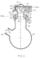
- FIG. 3 represents a classic example of a pump casing 50 provided with a duct 52 for supplying air from the outside, by means of a non-return valve 54.
- a variant would consist in that the duct 52 opens laterally into the cylinder A or B, through a light discovered when the piston is near its top dead center.
- FIG. 3 also shows refrigeration means in the form of fins 56 on the right-hand side, and another variant embodiment of the refrigeration means in the form of a water chamber 58 on the left-hand side.
- FIGS. 1 to 3 there is shown a second embodiment of the device according to the invention, for which the same reference numbers have been used as in FIGS. 1 to 3 for the parts fulfilling an identical function, but increased by 100.
- this device is here characterized in that it no longer comprises a transfer channel 30 serving successively to each of the cylinders as in the embodiment of FIGS. 1 and 2, but two separate and crossed transfer channels 130B, 130A each putting in turn the transit chambers 128A and 128B respectively, constituting the means of transit of intake air 108A, 108B, pistons 120A, 120B with the spaces under piston 106A, 106B, constituted by the pump casings respective when these are respectively in the vicinity of their top dead center and their bottom dead center.
- these crossed transfer channels 130B, 130A are, unlike the embodiment of FIGS. 1 to 3, always traversed in the same direction by the intake air coming from one or other of the pump casings.
- the space under piston 106A is in communication with the transit chamber 128B via the transfer channel 130A, while the transit chamber 128B communicates at this time through the light 109B formed in the skirt of the piston 120B with the self-supercharging duct 112 which opens onto the working chamber 136 by its inlet light 114A.
- the transit chambers can be in communication through the transfer channels 130A or 130B for suitable durations and periods of the cycle. In any case, the duration of communication must be long enough to allow scanning of the self-supercharging duct 112, then of the working chamber such as 136 in the scanning phase.
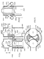
- the piston 220A, 220B of the cylinder 210A, 210B is constituted by a stepped piston so as to define the transit chamber 228A, 228B, constituting the means of transit of intake air 208A, 208B, by a zone vertical annular in permanent communication with the pump space 206A, 206B generated by the natural movement of the piston 220A, 220B and itself constituting the positive displacement pump.
- a duct 252A, 252B for supplying air from the outside via a non-return valve such as 254A is provided similarly to FIG. 3. It is thus understood that the stepped piston 220A, 220B sucks in the intake air from the outside when this piston descends towards bottom dead center as shown on the right-hand side of FIGS. 7a and 7b, and expels the air in the duct. self-supercharging 212A, 212B through the light 209A, 209B formed in the skirt of the piston such as 220A when the piston is in the vicinity of its top dead center, as shown in the left part of Figures 7a, 7b.
- FIGS. 7a and 7b using a stepped piston, results in the elimination of the transfer channels (30, FIGS. 1 to 3; and 130A, 130b, FIGS. 4 to 6) since the stepped piston ensures the function of positive displacement pump during its movement towards top dead center for the same cylinder including the transit chamber such as 220A, in operation.
- FIG. 7b also shows refrigeration means, for example in the form of conduits such as 260 drilled, or even produced by molding in a foundry, in the case of water cooling, a technique also known as name of "boron cooling", distributed around the self-supercharging duct 212A, 212B as shown in partial section along the trace line VIIb-VIIb of FIG. 7a.
- refrigeration means for example in the form of conduits such as 260 drilled, or even produced by molding in a foundry, in the case of water cooling, a technique also known as name of "boron cooling", distributed around the self-supercharging duct 212A, 212B as shown in partial section along the trace line VIIb-VIIb of FIG. 7a.
- FIGS. 7a and 7b using a stepped piston 220A, 220b, also makes it possible, by the appropriate choice of the ratio of its large diameter (D) to its small diameter (d), to increase the air flow supplied by the positive displacement pump.
- D large diameter
- d small diameter
- the aforementioned ratio D / d may in particular be greater than ⁇ 2.
- the engine will not be cooled at low loads by interrupting the engine cooling circuit, and in particular the supply channels including the self-supercharging ducts, while refrigerate from intermediate loads to the maximum load by opening the refrigeration circuit.
- the rise in temperature of the intake air increases their volume and thus produces a decrease in the volume of residual exhaust gases in the cylinder, which favorably influences the minimum flammability threshold of the purge air-residual gases mixture. mainly in the case of spark ignition engines.
- the low pressure turbo-compressor constitutes not only a means of raising the sweeping pressure but also a means, from a certain level of charge, of creating a positive pressure differential between the pressure of intake and exhaust pressure, in a manner well known to those skilled in the art.
Landscapes
- Engineering & Computer Science (AREA)
- Chemical & Material Sciences (AREA)
- Combustion & Propulsion (AREA)
- Mechanical Engineering (AREA)
- General Engineering & Computer Science (AREA)
- Supercharger (AREA)
- Compressor (AREA)
Claims (14)
- Vorrichtung zur Lufteinspeisung in einen Zylinder eines Zweitakt-Verbrennungsmotors mit mindestens einer Gruppe von zwei um 180° taktverschobenen Zylindern und Selbstaufladung, mit mindestens einem Selbstaufladekanal, der die Einlaßschlitze der beiden Zylinder einer Gruppe verbindet und den einzigen Weg für den Lufteinlaß in den in der Spülphase befindlichen Zylinder darstellt, wobei im Inneren oder unter dem Kolben des dazugehörigen Zylinders Einrichtungen vorgesehen sind, durch die die Einlaßluft hindurchströmt und die mindestens in dem Moment, in dem sich dieser Kolben des dazugehörigen Zylinders nahe dem oberen Totpunkt befindet, stromaufwärts von einer Einlaßluftquelle gespeist werden, während sie stromabwärts mit dem Selbstaufladekanal in Verbindung stehen, mit einer Verdrängerpumpe, die durch die natürliche Bewegung eines Kolbens zwischen seinem oberen und seinem unteren Totpunkt und umgekehrt gebildet wird und mit den Einrichtungen, durch die die Einlaßluft hindurchströmt (8A, 8B; 108A, 108B; 208A, 208B), verbunden ist, um ihnen Luft zuzuführen, dadurch gekennzeichnet, daß die Einlaßschlitze im Zylinder so angeordnet sind, daß sie vom Kolben länger freigegeben werden als die Auslaßschlitze, um eine Nachfüllwirkung sicherzustellen, daß die Vorrichtung mindestens eine Gruppe von zwei Selbstaufladekanälen (12) aufweist und die Durchströmeinrichtungen (8A, 8B; 108A, 108B; 208A, 208B) jeder Gruppe von Selbstaufladekanälen (12) symmetrisch Luft zuführen.
- Vorrichtung nach Anspruch 1 mit einem Stufenkolben (220A, 220B), dadurch gekennzeichnet, daß die vorgenannten Durchströmeinrichtungen (208A, 208B) und die vorgenannte Verdrängerpumpe ineinander übergehen und in den Kolben des dem Zylinder in der Spülphase zugeordneten Zylinders integriert sind.
- Vorrichtung nach Anspruch 1, dadurch gekennzeichnet, daß die vorgenannte Verdrängerpumpe durch die Kurbelgehäuse-Pumpe des in der Spülphase befindlichen Zylinders gebildet wird.
- Vorrichtung nach Anspruch 3, dadurch gekennzeichnet, daß die Durchströmeinrichtungen (8A, 8B; 108A, 108B) des Kolbens des dazugehörigen Zylinders über mindestens einen unterhalb des unteren Totpunkts angeordneten Überströmkanal (30; 130A, 130B) stromaufwärts intermittierend mit der Kurbelgehäuse-Pumpe des Zylinders in der Spülphase (wie 20B; 120A) in Verbindung stehen.
- Vorrichtung nach Anspruch 4, dadurch gekennzeichnet, daß jeder Überströmkanal (30) dazu dient, den beiden dazugehörigen Zylindern nacheinander Luft zuzuführen.
- Vorrichtung nach einem der Ansprüche 3 bis 5, dadurch gekennzeichnet, daß zu den Durchströmeinrichtungen (8A, 8B; 108A, 108B) eine Durchströmkammer gehört (28A, 28B; 128 A, 128B), die entweder durch einen kolbeninternen Hohlraum (128A, 128B) oder durch mindestens eine aus dem Vollen des Kolbens herausgearbeitete Aussparung (28A, 28B) zwischen dem Kolben und dem Zylinder gebildet wird und stromaufwärts intermittierend mit der Kurbelgehäuse-Pumpe und stromabwärts mit dem Selbstaufladekanal (12) verbunden ist.
- Vorrichtung nach Anspruch 6, dadurch gekennzeichnet, daß sie im Inneren des Kolbens (wie 20B) einen Hohlraum (22A, 22B) für die Zuführung der Einlaßluft aufweist, welcher stromaufwärts mit dem durch die Kurbelgehäuse-Pumpe gebildeten Raum unter dem Kolben (6A, 6B) in Verbindung steht und stromabwärts durch einen Schlitz (wie 38B) im Kolbenmantel (wie 20B) in diesen mündet, wobei dieser Schlitz über den vorgenannten Überströmkanal (30) durch die natürliche Bewegung jedes Kolbens in seinem Zylinder intermittierend mit den Durchströmeinrichtungen (wie 8A, 8B) des anderen dazugehörigen Kolbens (wie 20A) in Verbindung gebracht wird.
- Vorrichtung nach Anspruch 7, dadurch gekennzeichnet, daß der vorgenannte Hohlraum für die Luftzuführung (22A, 22B) ringförmig unter dem Kolbenboden ausgebildet ist und der Kolben außerdem einen senkrechten Kanal (wie 24B) für die Luftzufuhr vom Raum unter dem Kolben (wie 6B) aufweist, der im Inneren des Kolbens (wie 20B) in einem dem mittigen Überströmkanal (30) diametral gegenüberliegenden ringförmigen Sektor ausgeführt ist und den Raum unter dem Kolben (wie 6B) mit dem vorgenannten Hohlraum (22B) verbindet.
- Vorrichtung nach Anspruch 8, dadurch gekennzeichnet, daß der Raum (wie 26B) um die Lagerung der Pleuel- oder Kolbenstange (wie 20B) herum, der sich vorteilhafterweise bis unter den Kolbenboden erstreckt, stromabwärts durch Schlitze (wie 40B) mit dem vorgenannten ringförmigen Hohlraum (wie 22B), der sich seinerseits unter dem Boden (wie 21B) des Kolbens (wie 20B) erstreckt, in Verbindung steht.
- Vorrichtung nach einem der Ansprüche 2 bis 9, dadurch gekennzeichnet, daß die Einheit aus jeder Gruppe von zwei um 180° taktverschobenen Zylindern (10A, 10B; 210A, 210B) und Kolben (20A, 20B; 220A, 220B) symmetrisch bezüglich einer Längssymmetrieebene angeordnet ist, die durch die Achsen der beiden Zylinder geht.
- Vorrichtung nach einem der Ansprüche 4 oder 6, dadurch gekennzeichnet, daß sie zwei überkreuz angeordenete Überströmkanäle (130A, 130B) aufweist, die beide stromaufwärts ununterbrochen den Raum unter dem Kolben (106B bzw. 106A) mit stromabwärts intermittierend den Durchströmeinrichtungen (wie 108B) des Kolbens (wie 120B) des dazugehörigen Zylinders (wie 110B) verbinden.
- Vorrichtung nach einem der Ansprüche 2 bis 11, dadurch gekennzeichnet, daß jeder Kolben (20A, 20B; 120A, 120B; 220A; 220B) im wesentlichen vollkommen zylindrisch ausgeführt ist.
- Vorrichtung nach Anspruch 2, dadurch gekennzeichnet, daß bei jedem Stufenkolben (220A, 220B) das Verhältnis seines großen Durchmessers (D) zu seinem kleinen Durchmesser (d) größer ist als √2.
- Vorrichtung nach Anspruch 2, bei der der Motor mit einem externen Turbokompressor ausgestattet ist, dadurch gekennzeichnet, daß bei jedem Stufenkolben (220A, 220B) das Verhältnis seines großen Durchmessers (D) zu seinem kleinem Durchmesser (d) auf den kleinstmöglichen, zur Erzielung eines einwandfreien Laufs beim Anlassen und im Schwachlastbereich erforderlichen Wert reduziert ist.
Applications Claiming Priority (3)
| Application Number | Priority Date | Filing Date | Title |
|---|---|---|---|
| FR8804003A FR2629132A1 (fr) | 1988-03-25 | 1988-03-25 | Procede et dispositif d'alimentation en air d'un cylindre d'un moteur deux temps autosuralimente a au moins un groupe de deux cylindres cales a 180o par une chambre de transit d'air alimentee sous pression communiquant par intermittence avec un conduit d'autosuralimentation, et moteur |
| FR8804003 | 1988-03-25 | ||
| PCT/FR1989/000138 WO1989009329A1 (fr) | 1988-03-25 | 1989-03-24 | Procede et dispositif d'alimentation en air d'un cylindre d'un moteur deux temps autosuralimente a au moins un groupe de deux cylindres cales a 180° |
Publications (2)
| Publication Number | Publication Date |
|---|---|
| EP0481972A1 EP0481972A1 (de) | 1992-04-29 |
| EP0481972B1 true EP0481972B1 (de) | 1995-09-13 |
Family
ID=9364679
Family Applications (1)
| Application Number | Title | Priority Date | Filing Date |
|---|---|---|---|
| EP89904082A Expired - Lifetime EP0481972B1 (de) | 1988-03-25 | 1989-03-24 | Vorrichtung zur lufteinspeisung in den zylinder eines selbstaufgeladenen zweitaktmotors mit mindestens einer gruppe von zwei um 180 grade taktverschobenen zylindern |
Country Status (6)
| Country | Link |
|---|---|
| US (1) | US5156118A (de) |
| EP (1) | EP0481972B1 (de) |
| JP (1) | JP2715171B2 (de) |
| DE (1) | DE68924277T2 (de) |
| FR (1) | FR2629132A1 (de) |
| WO (1) | WO1989009329A1 (de) |
Families Citing this family (2)
| Publication number | Priority date | Publication date | Assignee | Title |
|---|---|---|---|---|
| RU2135788C1 (ru) * | 1998-04-22 | 1999-08-27 | Зуев Анатолий Алексеевич | Рабочий процесс двс с сообщающимися цилиндрами |
| CN102619613B (zh) * | 2011-01-26 | 2014-07-16 | 杨成元 | 泵压四冲程单缸分层旋涡燃烧节能汽油机 |
Family Cites Families (11)
| Publication number | Priority date | Publication date | Assignee | Title |
|---|---|---|---|---|
| US1546103A (en) * | 1923-11-20 | 1925-07-14 | Perez Manuel Humberto | Internal-combustion motor |
| FR593420A (fr) * | 1925-02-16 | 1925-08-24 | Carburateur | |
| US1866774A (en) * | 1929-11-18 | 1932-07-12 | Maher Bernard Stanley | Engine |
| US1904816A (en) * | 1930-02-14 | 1933-04-18 | George P Beaudry | Internal combustion engine |
| US2446094A (en) * | 1944-07-05 | 1948-07-27 | Harold E Mattice | Supercharging and scavenging internal-combustion engine |
| US2766650A (en) * | 1954-11-05 | 1956-10-16 | Ottavio A Capra | Heel plate assembly for a removable jaw wrench |
| CH569864A5 (de) * | 1973-09-26 | 1975-11-28 | Motosacoche Sa | |
| FR2319768A1 (fr) * | 1975-07-30 | 1977-02-25 | Leonard Paul | Perfectionnements aux moteurs deux temps |
| CH593420A5 (de) * | 1976-03-31 | 1977-11-30 | Motosacoche Sa | |
| US4250844A (en) * | 1979-04-05 | 1981-02-17 | Tews Jan H | Two-cycle engine and piston |
| FR2649158A1 (fr) * | 1989-06-30 | 1991-01-04 | Inst Francais Du Petrole | Dispositif de controle de debut d'introduction sous pression du melange carbure dans un moteur a combustion interne et son application au moteur 2 temps |
-
1988
- 1988-03-25 FR FR8804003A patent/FR2629132A1/fr not_active Withdrawn
-
1989
- 1989-03-24 US US07/576,421 patent/US5156118A/en not_active Expired - Fee Related
- 1989-03-24 EP EP89904082A patent/EP0481972B1/de not_active Expired - Lifetime
- 1989-03-24 JP JP1503757A patent/JP2715171B2/ja not_active Expired - Lifetime
- 1989-03-24 DE DE68924277T patent/DE68924277T2/de not_active Expired - Fee Related
- 1989-03-24 WO PCT/FR1989/000138 patent/WO1989009329A1/fr not_active Ceased
Also Published As
| Publication number | Publication date |
|---|---|
| DE68924277T2 (de) | 1996-04-25 |
| JPH03503440A (ja) | 1991-08-01 |
| WO1989009329A1 (fr) | 1989-10-05 |
| EP0481972A1 (de) | 1992-04-29 |
| DE68924277D1 (de) | 1995-10-19 |
| US5156118A (en) | 1992-10-20 |
| FR2629132A1 (fr) | 1989-09-29 |
| JP2715171B2 (ja) | 1998-02-18 |
Similar Documents
| Publication | Publication Date | Title |
|---|---|---|
| EP0189716B1 (de) | Einrichtung zur Kraftstoffeinspritzung in eine Brennkraftmaschine mit Hilfe von Druckluft oder -gas | |
| EP0302042B1 (de) | Sechs-Takt-Brennkraftmaschine | |
| EP1018597B1 (de) | Aufgeladene zweitakt- oder Viertaktbrennkraftmaschine | |
| EP0235481A1 (de) | Vorrichtung zum Einlass von Druckgasen in den Brennraum einer Brennkraftmaschine | |
| EP0104541B1 (de) | Verfahren zur Transformation von thermischer Energie in mechanische Energie mittels einer Brennkraftmaschine und diese Maschine | |
| FR2475127A1 (fr) | Generateur de gaz a variation de volume | |
| EP0063598B1 (de) | Zweitakt-axialkolbenmotor | |
| EP0481972B1 (de) | Vorrichtung zur lufteinspeisung in den zylinder eines selbstaufgeladenen zweitaktmotors mit mindestens einer gruppe von zwei um 180 grade taktverschobenen zylindern | |
| FR2583108A2 (fr) | Procede d'amelioration du fonctionnement d'un moteur a combustion interne, a cycle court, et moteur a combustion interne a fonctionnement ameliore a cycle court et a structure simplifiee | |
| FR2704903A1 (fr) | Procédé et dispositifs de contrôle de combustion d'un moteur quatre temps. | |
| EP0238584B1 (de) | Verfahren und vorrichtung zur regelung eines auspuffgaskreises für eine brennkraftmaschine | |
| EP0358655B1 (de) | Verfahren und einrichtung für eine zweitakt-brennkraftmaschine mit nachladung | |
| EP0217374B1 (de) | Kolben-Zylinder Einheit einer Zweitaktbrennkraftmaschine | |
| FR2531139A1 (fr) | Dispositif de controle d'un circuit de gaz d'une chambre de combustion | |
| FR2525687A1 (fr) | Moteur a combustion interne a piston alternatif a deux temps | |
| WO1986000374A1 (fr) | Procede d'amelioration du fonctionnement d'un moteur a combustion interne a deux temps | |
| FR2579669A1 (fr) | Moteur a combustion interne a pistons alternatifs | |
| EP0015792A1 (de) | Verfahren zum Laden eines Zwei-Takt-Verbrennungsmotors und Zwei-Takt-Verbrennungsmotoren mit ausbalancierendem Kolben und mit Kraftstoff/Luftgemisch-Einspritzung | |
| FR2676503A1 (fr) | Moteur thermique. | |
| FR2552493A1 (fr) | Moteur a combustion interne suralimente | |
| BE356902A (de) | ||
| FR2788306A1 (fr) | Moteur compresse a combustion interne a deux temps | |
| FR2810077A1 (fr) | Perfectionnements aux moteurs a deux temps | |
| EP0061984A2 (de) | Viertakt-Brennkraftmaschine mit innerer Verbrennung nach Diesel | |
| CH539776A (fr) | Moteur thermique |
Legal Events
| Date | Code | Title | Description |
|---|---|---|---|
| PUAI | Public reference made under article 153(3) epc to a published international application that has entered the european phase |
Free format text: ORIGINAL CODE: 0009012 |
|
| 17P | Request for examination filed |
Effective date: 19900921 |
|
| AK | Designated contracting states |
Kind code of ref document: A1 Designated state(s): BE DE FR GB IT |
|
| RAP1 | Party data changed (applicant data changed or rights of an application transferred) |
Owner name: CURTIL, REMI |
|
| 17Q | First examination report despatched |
Effective date: 19931228 |
|
| RAP1 | Party data changed (applicant data changed or rights of an application transferred) |
Owner name: CURTIL, REMI |
|
| GRAA | (expected) grant |
Free format text: ORIGINAL CODE: 0009210 |
|
| AK | Designated contracting states |
Kind code of ref document: B1 Designated state(s): BE DE FR GB IT |
|
| REF | Corresponds to: |
Ref document number: 68924277 Country of ref document: DE Date of ref document: 19951019 |
|
| ITF | It: translation for a ep patent filed | ||
| GBT | Gb: translation of ep patent filed (gb section 77(6)(a)/1977) |
Effective date: 19951215 |
|
| PLBE | No opposition filed within time limit |
Free format text: ORIGINAL CODE: 0009261 |
|
| 26N | No opposition filed | ||
| PGFP | Annual fee paid to national office [announced via postgrant information from national office to epo] |
Ref country code: FR Payment date: 19990216 Year of fee payment: 11 |
|
| PGFP | Annual fee paid to national office [announced via postgrant information from national office to epo] |
Ref country code: GB Payment date: 19990316 Year of fee payment: 11 |
|
| PGFP | Annual fee paid to national office [announced via postgrant information from national office to epo] |
Ref country code: DE Payment date: 19990317 Year of fee payment: 11 |
|
| PGFP | Annual fee paid to national office [announced via postgrant information from national office to epo] |
Ref country code: BE Payment date: 19990414 Year of fee payment: 11 |
|
| PG25 | Lapsed in a contracting state [announced via postgrant information from national office to epo] |
Ref country code: GB Free format text: LAPSE BECAUSE OF NON-PAYMENT OF DUE FEES Effective date: 20000324 |
|
| PG25 | Lapsed in a contracting state [announced via postgrant information from national office to epo] |
Ref country code: BE Free format text: LAPSE BECAUSE OF NON-PAYMENT OF DUE FEES Effective date: 20000331 |
|
| BERE | Be: lapsed |
Owner name: CURTIL REMI Effective date: 20000331 |
|
| GBPC | Gb: european patent ceased through non-payment of renewal fee |
Effective date: 20000324 |
|
| PG25 | Lapsed in a contracting state [announced via postgrant information from national office to epo] |
Ref country code: FR Free format text: LAPSE BECAUSE OF NON-PAYMENT OF DUE FEES Effective date: 20001130 |
|
| REG | Reference to a national code |
Ref country code: FR Ref legal event code: ST |
|
| PG25 | Lapsed in a contracting state [announced via postgrant information from national office to epo] |
Ref country code: DE Free format text: LAPSE BECAUSE OF NON-PAYMENT OF DUE FEES Effective date: 20010103 |
|
| PG25 | Lapsed in a contracting state [announced via postgrant information from national office to epo] |
Ref country code: IT Free format text: LAPSE BECAUSE OF NON-PAYMENT OF DUE FEES;WARNING: LAPSES OF ITALIAN PATENTS WITH EFFECTIVE DATE BEFORE 2007 MAY HAVE OCCURRED AT ANY TIME BEFORE 2007. THE CORRECT EFFECTIVE DATE MAY BE DIFFERENT FROM THE ONE RECORDED. Effective date: 20050324 |