EP0482149B1 - Abgabesystem fuer fluessigkeiten mit pipette mit voreinstellbarer position fuer die spitze - Google Patents
Abgabesystem fuer fluessigkeiten mit pipette mit voreinstellbarer position fuer die spitze Download PDFInfo
- Publication number
- EP0482149B1 EP0482149B1 EP91908152A EP91908152A EP0482149B1 EP 0482149 B1 EP0482149 B1 EP 0482149B1 EP 91908152 A EP91908152 A EP 91908152A EP 91908152 A EP91908152 A EP 91908152A EP 0482149 B1 EP0482149 B1 EP 0482149B1
- Authority
- EP
- European Patent Office
- Prior art keywords
- tip
- holder
- stem
- pipette
- chamber
- Prior art date
- Legal status (The legal status is an assumption and is not a legal conclusion. Google has not performed a legal analysis and makes no representation as to the accuracy of the status listed.)
- Expired - Lifetime
Links
- 239000012530 fluid Substances 0.000 title abstract description 40
- 238000003780 insertion Methods 0.000 claims description 17
- 230000037431 insertion Effects 0.000 claims description 17
- 238000000034 method Methods 0.000 claims description 16
- 239000000463 material Substances 0.000 claims description 10
- 230000009471 action Effects 0.000 claims description 3
- 239000012858 resilient material Substances 0.000 claims description 2
- 238000003556 assay Methods 0.000 description 19
- 238000012360 testing method Methods 0.000 description 15
- 239000003153 chemical reaction reagent Substances 0.000 description 12
- 238000010276 construction Methods 0.000 description 10
- 238000013096 assay test Methods 0.000 description 8
- 238000006243 chemical reaction Methods 0.000 description 5
- 238000004519 manufacturing process Methods 0.000 description 5
- 238000003860 storage Methods 0.000 description 5
- 230000007246 mechanism Effects 0.000 description 4
- 239000002184 metal Substances 0.000 description 4
- 230000008859 change Effects 0.000 description 3
- 230000005489 elastic deformation Effects 0.000 description 3
- 238000000465 moulding Methods 0.000 description 3
- 230000004044 response Effects 0.000 description 3
- 230000000717 retained effect Effects 0.000 description 3
- 238000013519 translation Methods 0.000 description 3
- 238000006073 displacement reaction Methods 0.000 description 2
- 230000036541 health Effects 0.000 description 2
- 238000011534 incubation Methods 0.000 description 2
- 230000001678 irradiating effect Effects 0.000 description 2
- 230000013011 mating Effects 0.000 description 2
- 239000004033 plastic Substances 0.000 description 2
- 230000008569 process Effects 0.000 description 2
- 241000894007 species Species 0.000 description 2
- 230000001360 synchronised effect Effects 0.000 description 2
- 238000012546 transfer Methods 0.000 description 2
- 206010000060 Abdominal distension Diseases 0.000 description 1
- 241000217377 Amblema plicata Species 0.000 description 1
- 239000004677 Nylon Substances 0.000 description 1
- 239000012491 analyte Substances 0.000 description 1
- 230000004323 axial length Effects 0.000 description 1
- 239000013060 biological fluid Substances 0.000 description 1
- 239000008280 blood Substances 0.000 description 1
- 210000004369 blood Anatomy 0.000 description 1
- 238000007705 chemical test Methods 0.000 description 1
- 230000006835 compression Effects 0.000 description 1
- 238000007906 compression Methods 0.000 description 1
- 238000011109 contamination Methods 0.000 description 1
- 238000013461 design Methods 0.000 description 1
- 201000010099 disease Diseases 0.000 description 1
- 208000037265 diseases, disorders, signs and symptoms Diseases 0.000 description 1
- 230000000694 effects Effects 0.000 description 1
- 238000000605 extraction Methods 0.000 description 1
- 230000006870 function Effects 0.000 description 1
- 238000005286 illumination Methods 0.000 description 1
- 230000006698 induction Effects 0.000 description 1
- 238000009434 installation Methods 0.000 description 1
- 230000003993 interaction Effects 0.000 description 1
- 238000005461 lubrication Methods 0.000 description 1
- 229920001778 nylon Polymers 0.000 description 1
- 210000002381 plasma Anatomy 0.000 description 1
- 229920001343 polytetrafluoroethylene Polymers 0.000 description 1
- 238000007789 sealing Methods 0.000 description 1
- 210000002966 serum Anatomy 0.000 description 1
- 229910001220 stainless steel Inorganic materials 0.000 description 1
- 239000010935 stainless steel Substances 0.000 description 1
- 239000000126 substance Substances 0.000 description 1
- 238000010998 test method Methods 0.000 description 1
- 229940126585 therapeutic drug Drugs 0.000 description 1
Images



Classifications
-
- B—PERFORMING OPERATIONS; TRANSPORTING
- B01—PHYSICAL OR CHEMICAL PROCESSES OR APPARATUS IN GENERAL
- B01L—CHEMICAL OR PHYSICAL LABORATORY APPARATUS FOR GENERAL USE
- B01L3/00—Containers or dishes for laboratory use, e.g. laboratory glassware; Droppers
- B01L3/02—Burettes; Pipettes
- B01L3/0275—Interchangeable or disposable dispensing tips
Definitions
- the application is directed to a fluid dispensing system and in particular to one which includes a pipette assembly adapted for use with disposable pipette tips.
- Automated test equipment allows large numbers of test samples to be processed rapidly. Such equipment is employed in health care institutions including hospitals and laboratories. Biological fluids, such as whole blood, plasma or serum are tested to find evidence of disease, to monitor therapeutic drug levels, etc.
- a sample of the test fluid is typically provided in a sample cup and all of the process steps including pipetting of the sample onto an assay test element, incubation and readout of the signal obtained are carried out automatically. All the process steps can be carried out while the assay test element is carried by a conveyor within a temperature controlled chamber. Further, in such instruments disposable pipette tips are typically used for the delivery of one fluid only and then discarded so as to avoid contamination which could lead to errors in the assay result.
- the orifice of the pipette tip be located at a predetermined, precisely controlled location above the assay element to prevent spilling or splashing of the fluid and to ensure the transfer of a precise amount of fluid.
- the fluid dispensing system which includes a pipette is used to transfer sample fluid and/or test reagents from storage cups or wells within the instrument to the assay test element.
- the pipette includes a hollow tube or stem typically of metal, which is adapted to cooperate with a disposable pipette tip, which is typically made of a polymeric material.
- the disposable pipette tips are provided in a storage tray within the instrument. Initially, the pipette is advanced downwardly to secure a disposable tip by frictional contact. Thereafter, a predetermined amount of fluid is aspirated into the pipette tip and the tip is then moved automatically to a dispense position above an assay test element where a predetermined volume of the fluid is dispensed to the assay element. Upon completion of the dispense step the tip is discarded and a clean disposable tip is used for the next dispense step.
- EP-A-0 148 333 discloses a pipette assembly comprising a holder, a tip and means for retaining the holder in the tip. More in particular, the holder and the tip, both include a crown and a stem. In the crown of the tip is a chamber into which the stem of the holder is to be inserted. The tip has a passage extending along its central axis from a distal port of that tip in order to communicate with the tip chamber at a distal end of that chamber. At the distal end of the chamber a ledge is located at a predetermined distance from the distal end of the tip. This ledge encircles the end of the stem passage.
- the holder has a passage extending along a central axis of the stem to a distal port.
- a surface of this distal port is configurated so as to mate with the ledge to position the holder distal port at the predetermined distance of the tip distal port.
- the chamber comprises a circumferential sealing rib axially spaced from the pipette seat to form an air seal.
- a fluid dispensing system which includes a pipette assembly and a disposable pipette tip. It is an object of the invention to provide a system wherein disposable pipette tips can be repetitively removed and replaced whereby the orifice of each tip attached to the pipette assembly is located at substantially the same distance from the stem of the pipette assembly on which the tip is carried.
- the pipette assembly is incorporated in an automated analytical instrument, the pipette can be positioned accurately in the dispense position by a microprocessor controlled transport assembly, the latter having a vertical drive for raising and lowering the pipette assembly.
- the pipette assembly is prepared for reuse by removal of the used tip and replacing it with a new one.
- the used tip can be removed by moving the pipette into a tip extractor which envelops a lip formed around the upper end of the tip and raising the pipette assembly to cause the pipette tip to be removed and caught by a collection receptable.
- a replacement tip is provided on the pipette stem by positioning the pipette assembly above a new tip located on a pipette tip holder and lowering the pipette assembly such that the stem engages a proximal end of the tip.
- the fluid dispense system comprises a pipette assembly having a pipette tip holder which includes a crown and a stem extending from the crown, and a disposable pipette tip.
- the pipette tip has a chamber for receiving the stem of the tip holder.
- a snap-action device located along an interface between the holder stem and the tip crown retains the holder stem in the tip chamber.
- the tip stem has a passage extending along a central axis of the tip from a distal port of the tip to communicate with the tip chamber at a distal end of the tip chamber.
- the tip crown is constructed with a ledge at the distal end of the tip chamber, the ledge being located at a predetermined distance from the distal port of the tip.
- the ledge encircles a proximal end of the stem passage. It has an edge which contacts the surface of the holder distal port to form a seal upon insertion of the holder stem into the tip chamber.
- the holder stem has a passage extending along a central axis of the holder stem to a distal port of the holder stem to communicate with the tip passage upon insertion of the holder stem into the tlp chamber.
- a surface of the distal part of the holder stem is configured to mate with the ledge so as to position the holder distal part at the predetermined distance from the tip orifice. More in particular, the nose surface of the holder stem extends transversely away from the distal part of the holder and then extends further in an inclined fashion relative to the axis as a skirt of the nose.
- the ledge in the pipette tip chamber is advantageously constructed of a resilient material, preferable polymeric, to form a fluid seal with the distal part of the holder.
- the vertical drive preferably comprises a stepper motor for accurate positioning of the pipette.
- the vertical drive is connected to the pipette by a spring-loaded lost-motion connection which allows relative motion between the pipette and the vertical drive upon a contacting of the holder with a replacement tip on the tray.
- Inner and outer rings may also be provided along an interface between the tip cavity and the holder stem to provide a further fluid seal.
- FIG. 1 there is shown an analytical instrument 20 which provides automatically a sequence of process steps to accomplish an assay of a test sample.
- a plurality of assay modules 22 are employed within the instrument 20 to increase the throughput rate, one process step being carried out with one module concurrently with the performance of other process steps with other modules.
- the modules 22 are illustrated with respect to a preferred embodiment thereof which includes one or more chambers in the housing. Such chambers may be configured as wells, or reservoirs, for the storage and/or mixing of fluids which are used in the assay procedure or the chambers may culminate in an opening to permit fluids to be provided to a reaction zone within the module.
- the chambers are formed integrally within the housing of the module.
- the analytical instrument 20 includes a turntable or carousel 24 which is rotated about an axle 26 by a motor 28.
- the motor 28 may be mechanically coupled to the carousel 24 by a gear 30 or by a belt drive (not shown).
- the carousel 24 carries the modules 22 from one work station to another work station, two such work stations 32 and 34 being shown, by way of example, in Fig. 1.
- the carousel 24 rotates within a temperature controlled chamber 36 having a heater 38 for maintaining a desired temperature at the various work stations so as to allow for a process step of incubation.
- Work station 32 is a pipetting station whereat sample fluid and any other required fluid test reagent(s) are delivered to the assay modules 22.
- sample fluid and any other required fluid test reagent(s) are delivered to the assay modules 22.
- the pipettes, 40 and 42 are positioned and operated by a pipette mechanism 44 mechanically connected to the pipettes 40 and 42, as indicated by dashed lines.
- a detectable change is effected corresponding to the presence of an analyte or component of interest in the sample fluid.
- the detectable change may be a color change which may be read spectrophotometrically such as with a densitometer or, in an assay method based on fluorescent-labeled biologically active species or one which involves the generation of a fluorescent species as a result of a reaction between test reagents, a fluorescent output signal can be generated and read spectrofluorometrically.
- Such detectable changes may be read from above or below the assay module.
- a fluorometer 46 for irradiating the reaction zone within the assay module and for measuring the fluorescence emitted from the fluorescent species present therein.
- the carousel 24 may be arranged so as to accomodate varying numbers of assay modules 22.
- Each position, or berth 54 for holding an assay module is provided in this embodiment with a small aperture 56 to allow the irradiating illumination to reach the reaction zone in the assay module and to permit the fluorescent emissions to be collected and measured.
- an injector 58 for inserting a module 22 in an empty berth 54, the injector 58 having an arm 60 for gripping a module 22 during the insertion operation.
- the injector 58 also serves to extract a module from a berth 54 by use of the arm 60 upon completion of a test procedure. Operation of the motor 28, the pipette mechanism 44, the fluorometer 46 and the injector 58 are synchronized by means of a microprocessor 62.
- Fig. 2 provides detail in the construction of the pipette mechanism 44 of Fig. 1.
- the pipette mechanism 44 will be described hereinafter as having a pipette transport 64 operative with only one of the pipettes, namely, the pipette 40.
- the transport 64 provides for relative movement, in two dimensions, between the pipette 40 and a set of reservoirs 66.
- the reservoirs 66 are located at a distance from a module 22 on the carousel 24, the reservoirs 66 serving to store reagents useful in carrying out assay tests by the analytical instrument 20.
- the reservoirs 66 are located on a movable tray or table 68 which also holds a set of tips 70 which are to be affixed to a stem 72 of the pipette 40.
- the pipette 40 is translatable in the X direction along a box beam 74 of the transport 64, and the table 68 is translatable in the Y direction by riding along a rail 76 of the transport 64.
- a vertical drive 78 is located within the beam 74 and serves to raise and to lower the pipette 40 in the Z direction.
- a horizontal drive 80 is located within the box beam 74, and drives the pipette in the X direction.
- the vertical drive 78 and the horizontal drive 80 are of conventional design, and are indicated in simplified fashion in Fig. 2. Briefly, the vertical drive 78 may be described as comprising a wheel 82 slidably mounted to a spline shaft 84 which, alternatively, may have a square cross section. The shaft 84 is rotated by a motor 86.
- the horizontal drive 80 includes a base 88 which slides in the X direction along the beam 74 in response to rotation of a motor 90.
- the motor 90 drives a belt 92 through a pulley 94, the belt 92 being connected to the base 88 for translating the base 88 upon rotation of the pulley 94 by the motor 90.
- a fixture 96 upstanding from the base 88 slides the wheel 82 along the shaft 84 upon movement of the base 88 so that the wheel 82 stays in fixed position relative to the base 88.
- the pipette 40 passes through the base 88 so as to be translated in the X direction by the base 88.
- the wheel 82 is mechanically connected to the pipette 40, as by gear teeth on the wheel 82, or by means of a belt drive (not shown).
- the mechanical connection of the wheel 82 to the pipette 40 provides for a translation of the pipette 40 in the Z direction upon rotation of the wheel 82 by the motor 86.
- a belt drive 98 may be employed, similarly, for driving the table 68 in the Y direction in response to rotation of a motor 100 affixed to the rail 76.
- the motor 28 is under control of the microprocessor 62.
- motors 100, 90, and 86 are also under control of the microprocessor 62. Connections of the motors 28, 100, 90, and 86 are indicated in Fig. 2 by terminals A, B. C, and D, respectively.
- movement of the pipette 40 can be synchronized with a positioning of the module 22 by the carousel 24 to a location directly beneath the beam 74.
- a slot 102 is provided in a top wall 104 of the temperature controlled chamber 36. The slot 102 is parallel to the beam 74.
- the location of the slot 102 relative to the beam 74 permits the stem 72 of the pipette 40 to be lowered through the slot 102 selectively above a desired compartment of a plurality of compartments 106 of a module 22.
- the length of the slot 102 is commensurate with the length of the module 22 to permit displacement of the stem 72 in the X direction for alignment with a selected one of the compartments 106.
- the slot 102 is relatively narrow, and has a width large enough to clear the stem 72 and the tip 70 mounted on the distal end of the stem 72.
- the area occupied by the slot 102 is sufficiently small to preclude any significant amount of air flow between the interior and the exterior of the chamber 36. Thereby, the slot 102 has no more than a negligible effect in the control of the chamber temperature, which temperature is controlled by the heater 38 (Fig. 1).
- Fluid reagent is drawn into the pipette tip 70 and expelled from the tip 70 by vacuum pressure delivered to the pipette 40 by a suction unit which is of well-known form and is located within the pipette 40.
- the suction unit comprises a near actuator 108 driven by a stepping motor (not shown) for driving a piston 110 via a rod 112.
- the piston 110 connects via a conduit 114 which passes through the stem 72 and into the tip 70.
- the microprocessor 62 commands the actuator 108 to apply vacuum for inducting fluid, and for releasing vacuum and applying positive pressure, if necessary, to expel the fluid reagent. Induction of fluid is done from a selected one of the reservoirs 66.
- Expelling of the fluid reagent is accomplished only when the tip 70 is in the position for dispensing the fluid to the selected one of the compartments 106 in the designated module 22. It is noted also that fluid reagent can be withdrawn also at one of the compartments 106 of the module 22 to be dispensed in another of the compartments 106. In this respect, a reservoir for storage of fluid reagent can be located directly within the module 22 or remote from the module 22, as at the table 68.
- the locations of the various reservoirs 66 of the table 68 are stored in a memory of the microprocessor 62. This enables the microprocessor 62 to move the table 68 to a specific address in the Y direction, and to move the pipette 40 to a specific address in the X direction, the X and the Y components of the address fully identifying the requisite one of the reservoirs 66. In similar fashion, the microprocessor 62 stores locations of the available tips 70 held by the table 68 so that successive ones of the tips 70 can be selected for affixation to the stem 72.
- the transport 64 is operative in the process of affixing a tip 70 to the stem 72 of a pipette 40, and in the detachment of the tip 70 from the stem 72.
- the procedure begins by a lifting of the pipette 40 so that the tip 70 clears the slot 102.
- the pipette 40 is then free to move along the beam 74 to an extractor 116.
- the extractor 116 has a semicircular channel 118 cut out in the edge of a horizontal portion of the extractor 116, the channel 118 having a diameter large enough to permit clearance of the stem 72 by the channel 118, but small enough to permit engagement of the channel 118 with the proximal end of the tip 70.
- the pipette 40 is brought towards the extractor 116 with the tip 70 being below the channel 118.
- the stem 72 enters the channel 118 after which the pipette 40 is raised to engage the tip 70 with the extractor 116.
- the tip 70 remains stationary as the stem 72 lifts out of the tip 70. Thereupon, the tip 70 falls into a bin 120 for collection of used tips 70. It is advisable to employ the extractor 116 at the beginning of operation of the test system 20 to ensure that the stem 72 is free for affixation of a new tip 70.
- the pipette 40 is brought, by displacement in the X direction, to a location above the table 68, whereupon the table 68 is translated in the Y direction to bring the stem 72 above and in registration with a selected tip 70 held by the table 68.
- the pipette 40 then advances downward, along a central longitudinal axis of the pipette 40, to make contact with the interior surface of the tip 70. Thereupon, the pipette 40 is raised, and the tip 70 is retained on the distal end of the stem 72 by a feature of the invention described in the following.
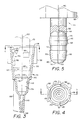
- the pipette 40 includes a novel pipette assembly 122 comprising the tip 70 and a tip holder 124.
- the tip 70 is formed as a hollow body comprising a crown 126 and a stem 128 which extends downwardly from the crown 126 in the normal vertical attitude of the pipette 40.
- the holder 124 is also formed as a hollow body and comprises a crown 130 and the aforementioned stem 72 which extends downwardly from the crown 130 in the normal vertical attitude of the pipette 40. Included within the tip crown 126 is a chamber 132 for receiving the holder stem 72.
- the chamber 132 forms a part of a passage 134 which extends from a proximal end 136 of the tip 70 to a distal port 138 at the far end of the tip stem 128.
- the tip passage 134 includes a relatively narrow bore 140 opening at the distal port 138, the opposite end of the bore 140 widening into a bowl 142 which communicates with the tip chamber 132.
- the tip bowl 142 has sufficient volume for storage of fluid drawn in through the tip bore 140 which fluid is to be expelled later via the tip bore 140.
- the holder 124 is also formed of a hollow body and includes a chamber 144 located in the holder crown 130, the holder 124 including a passage 146 which extends from the chamber 144 through the holder stem 72 to a distal port 148 at the end of the stem 72.
- the holder passage 146 and the tip passage 134 together constitute the conduit 114 previously disclosed in Fig. 2.
- a set of fins 150 extend radially outward from the tip crown 126 for supporting the tip 70 in an aperture 152 of the table 68 (Figs. 2 and 7).
- the tip 70 is retained upon the holder stem 72 by a snap-lock retainer 154 (Fig. 3) formed along an interface between a sidewall 156 of the tip 70 and a sidewall 158 of the holder 124.
- the sidewall 156 encloses the tip chamber 132
- the sidewall 158 encloses the holder passage 146 (Fig. 5).
- One portion of the retainer 154 is formed as an assembly of ridges 160 formed of the inner surface of the tip sidewall 156 and extending inwardly towards a central longitudinal axis 162 of the tip 70.
- three ridges 160 are provided, the ridges 160 being disposed symmetrically about the axis 162.
- the cross section of the tip sidewall 156 is circular.
- An inner edge of each ridge 160 is formed as a chord of the circular cross section of the tip sidewall 156.
- the holder stem 72 has a generally circular cylindrical shape about a longitudinal central axis 164 of the holder 124.
- a second part of the retainer 154 is formed as a protuberance 166 which extends from the outer surface of the holder sidewall 158 with circular symmetry about the holder axis 164.
- the tip 70 of Fig. 3 there is superposed an outline in phantom view of the holder stem 72 to portray an interrelationship among surface features of the holder stem 72 and features of the inner surface of the tip sidewall 156.
- the tip sidewall 156 at the tip crown 126 is tapered with the cross section of the tip chamber 132 increasing in size with progression from the distal end of the chamber 132 towards the proximal end 136 of the tip 70. This facilitates manufacture of the tip 70 by a process of molding the tip 70 from a polymeric material.
- the polymeric material should be relatively soft and resilient to permit elastic deformation of the tip 70 during insertion of the holder stem 72 into the tip chamber 132.
- a longitudinal ray of the sidewall 156 of the truncated conic surface of the tip chamber 132 is inclined relative to the tip axis 162. Similar inclination of a ray of the surface of the tip sidewall 156 is present in the extension of the sidewall 156 to the tip bowl 142 and to the tip bore 140 to provide taper of the tip stem 128 to facilitate manufacture by molding.
- the entire tip 70 is molded as an integral unit.
- the protuberance 166 has a leading surface 168 and a trailing surface 170 which are inclined relative to the holder axis 164. This permits engagement of the protuberance 166 with the tip ridges 160, and distention of the ridges 160 away from the tip axis 162 during insertion of the holder stem 72 into the tip chamber 132 and during a retraction of the holder stem 72 from the tip chamber 132.
- the tip axis 162 and the holder axis 164 coincide. As can be seen with reference to Figs.
- the minimum distance of each ridge 160 from the axis 162 is less than the maximum distance of the protuberance 166 from the axis 164. This produces a snap-action as each of the ridges 160 slide up the leading surface 168 and then begin to slide down the trailing surface 170 of the protuberance 166.
- a ledge 172 in the tip sidewall 156, the ledge 172 extending in a plane transverse to the axis 162.
- a lip 174 which extends toward the proximal end 136 of the tip 70.
- the lip 174 engages with a surface 176 of a nose 178 of the holder stem 72.
- the nose surface 176 extends transversely away from the distal port 148 of the holder 124, and then extends further in an inclined fashion relative to the axis 164 as a skirt 180 of the nose 178.
- the inclination of a ray of the skirt 180 relative to the axis 164 is approximately 45 degrees.
- the nose 178 advances to the ledge 172 with the skirt 180 abutting the lip 174 of the ledge 172.
- the inclination of the trailing surface 170 coacts with the ridges 160 to develop a force having a longitudinal component along the axis 162.
- the force of the retainer 154 urges the holder stem 72 towards the distal end of the tip 70, thereby driving the skirt 180 against the lip 174 with slight deformation of the lip 174.
- the deformation of the lip 174 conforms the lip 174 to the surface of the skirt 180 and provides a seal 182 which blocks all flow of air from the tip bowl 142 into the tip chamber 132.
- the force along the axis 162 developed by the retainer 154 is provided by the resilience of the plastic material of the tip sidewall 156 which enables the tip sidewall 156 and the assembly of ridges 160 to act as a spring for securing the holder stem 72 within the tip chamber 132.
- the tip sidewall 156 and the assembly of ridges 160 readily deform to clear the protuberance 166, the force exerted by the extractor 116 upon the proximal end 136 of the tip 70 exceeding the snap-action force of the retainer 154 to allow extraction of the stem 72.
- a second seal 184 is located along the interface between the holder sidewall 158 and the tip sidewall 156 in the chamber 132.
- the holder stem 72 is provided with an outwardly extending ring 186 which forms a part of the nose 178.
- An inwardly extending ring 188 is located on the inner surface of the tip sidewall 156 in the chamber 132, and is disposed with circular symmetry about the axis 162.
- the inwardly extending ring 188 is arranged between the first-mentioned seal 182 and the retainer 154.
- the outwardly extending ring 186 is tapered for increasing diameter with progression away from the distal port 148.
- the taper allows for engagement of the outwardly extending ring 188 with the inwardly extending ring 186 to form the seal 184 upon insertion of the holder stem 72 within the chamber 132.
- the ring 186 of the holder 124 extends for a greater distance along the holder axis 164 than the corresponding extent of the ring 188 of the tip 70 along the tip axis 162 to allow for sliding of the nose 178 past the tip ring 188.
- the resilience of the plastic material of the tip sidewall 156 which material is also employed in the construction of the ring 188, allows for elastic deformation of the ring 188 as is slides along the tapered surface of the ring 186 on the nose 178.
- a feature of the invention is the establishment of a predetermined length to the pipette assembly 122 including the holder 124 in conjunction with any one of a number of replacement tips 70.
- the total length of the pipette assembly 122 has the desired predetermined length, which length is measured from the tip distal port 138 to a reference point in the holder 124, such as the distal end of the nose 178 or the distal edge of the crown 130.
- This predetermined length is maintained accurately among all of the tips 70 by the abutment of the skirt 180 of the nose 178 against the lip 174 of the ledge 172.
- the retainer 154 by urging the holder stem 72 against the ledge 172 ensures accurate mating of the skirt 180 with the lip 174 to maintain the desired predetermined length of the pipette assembly 122.
- the forward edges (the edges closest to the tip distal port 138) of the ridges 160 and the ring 188 are provided with a taper which facilitates the molding operation in the manufacture of the tip 70.
- the taper facilitates removal of the tip 70 from the part of the mold located within the tip 70 by allowing the ridges 160 and the ring 188 to slide over corresponding depressions in the mold.
- testing of a completed tip 70 is provided by use of a circular pin-shaped gauge which is inserted into the tip 70 to contact the lip 174 to test the circumference thereof.
- a longitudinal ray of the tip bore 140 is inclined at an an angle of 2 degrees with respect to the tip axis 162.
- the same angle of inclination is employed for longitudinal rays in the sidewall 156 of the tip bowl 142 and in a forward portion of the sidewall of the tip chamber 132.
- the forward portion of the sidewall of the tip chamber 132 extends approximately one-half of the axial length of the chamber 132.
- the sidewall 156 of the remaining half of the chamber 132 is tapered to a greater extent such that a ray of the sidewall is inclined at an angle of approximately 4 degrees.
- the minimum diameter of a circular tangent to the inwardly extending edges of the ridges 160 is 0.270 inches with a tolerance of 0.002 inches.
- the angle of inclination of a ray of the sidewall 156 at the distal end of the tip bowl 142 is approximately 45 degrees.
- the inner diameter of the tip ring 188 of the second seal 184 is in the range of 0.243 inches to 0.246 inches.
- the diameter of the lip 174 of the ledge 172 is 0.187 inches with a tolerance of 0.002 inches.
- the extent of the lip 174 along the lip axis 162 is 0.005 inches.
- the ring 186 of the nose 178 has a maximum diameter of 0.248 inches and a minimum diameter of 0.238 inches both with a tolerance of 0.002 inches.
- the ring 186 of the nose 178 is tapered such that a longitudinal ray of the surface of the ring is inclined relative to the holder axis 164 at an angle of 3 degrees.
- the maximum diameter is 0.286 inches with a tolerance of 0.002 inches
- the minimum diameter at the distal and proximal ends of the protuberance 166 is 0.20 inches with a tolerance of 0.002 inches.
- the leading and the trailing surfaces 168 and 170 of the protuberance 166 are tapered such that a ray of the surfaces is inclined at an angle of 15 degrees relative to the holder axis 164.
- the pipette tip has three notches spaced about 120° apart cut into the proximal end 136 of the tip 70.
- One such notch 151 is shown in Fig. 3 for purposes of illustration.
- the notches 151 are about 0.1 inch deep, about 0.1 inch across at the top and preferably form an included angle of about 25° with relation to axis 162.
- the notches 151 are arranged such that the ridges 160 are not formed directly below them.
- the notches 151 allow the protruberance 166 to be extended outwardly farther from axis 164 (Fig. 5).
- the leading surface 170 of the protruberance 166 can be at a larger angle, for example, 30°, relative to axis 164 and the trailing surface 170 can remain the same, e.g., 15°.
- the tip holder 124 is constructed of a metal, such as stainless steel, and is provided with a smooth surface to facilitate sliding into the tip chamber 132.
- the length of the pipette assembly 122 is selected in accordance with dimensions of the analytical instrument employed in the system 20 (Figs. 1 and 2), including dimensions of the carousel 24, the module 22, and the chamber 36.
- the length of the tip 70 as measured from the distal port 138 to the proximal edge of the lip 174, is in the range of 0.750 inch to 0.754 inch.
- the distance from the distal port 148 to the center of the protuberance 166 (the outwardly extending peak) is 0.470 inches.
- the maximum width of a ridge 160 as measured in a plane transverse to the tip axis 162, is approximately 0.015 inches.
- the interior diameter of the tip chamber 132 at the ledge 172 is 0.250 inch.
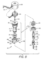
- the pipette 40 further comprises a spring-loaded lost-motion connection 190 which permits use of a stepping motor, the motor 86, for operating the vertical drive 78.
- a stepping motor advances stepwise. Therefore, by use of a stepping motor in the vertical drive 78, the pipette 40 moves upward and downward in a sequence of incremental steps.
- the sequence of incremental steps is advantageous for control by the microprocessor 62 in that accurate control of the position of the pipette 40 can be attained by the microprocesspr by the designation of a specific number of steps for advancement or retraction of the pipette 40.
- FIG. 6 shows the situation in which the pipette 40 can be advanced or retracted in the vertical direction freely.
- Fig. 7 shows the situation in which downward advancement of the pipette 40 is constrained by the table 68 which supplies the replacement tips 70 for the pipette 40.
- the table 68 which supplies the replacement tips 70 for the pipette 40.
- the fins 150 are being pressed against the table 68 (Fig. 7.
- the pipette assembly 122 is restrained by the table 68 from further downward advancement even though the motor 86 may still be activated electrically for further advancement.
- the lost-motion connection 190 provides this function so that even if the number of steps directed by the microprocessor 62 exceed the amount required to seat the nose 178 against the lip 174, the lost-motion connection 190 allows the pipette 40 to remain stationary while the vertical drive 78 continues to advance downwardly.
- the spring 192 in the connection 190 maintains downward force against the holder 124 during the additional advancement of the vertical drive 78, the force exerted by the spring 192 being sufficient to seat the nose 178 of the holder 124 against the lip 174 of the tip 70.
- the lost-motion connection 190 further comprises a support body 194 having a crown 196 and a stem 198 extending downward from the crown 196, a slide 200 comprising a base 202 extending transversely of an axis of the pipette 40 and a collar 204 extending from the base 202 parallel to the pipette axis, and a nut 206 which is knurled to permit tightening by hand.
- the slide 200 slides along the stem 198, and includes a set screw 208 which mounts within the collar 204 and extends into a slot 210 in the stem 198 to allow translation of the slide 200 along the stem 198 while preventing rotation of the slide 200 about the stem 198.
- two "O" rings 212 may be positioned on opposite sides of the set screw 208 for encircling the stem 198 to maintain lubrication between the stem 198 and the slide 200.
- Apertures 214 in the base 202 allow connection of the slide 200 to an outer housing 216 of the vertical drive 78. Securing of the base 202 to the housing 216 may be accomplished by screws (not shown) passing through the apertures 214 into the housing 216.
- the linear actuator 108 is located above the crown 196 and is enclosed within a cap 218 which is secured by threads to the crown 196.
- the motor of the actuator 108 operates a positioning element 220 by linear translation of the element 220 along the pipette axis.
- a piston assembly 222 which is supported within the chamber 144 of the holder 124, and extends upwardly through a central bore 224 of the support body 194 to connect with the positioning element 220.
- the piston assembly 222 is of well-known construction and is available commercially, the piston assembly 222 having the piston rod 112 which drives the piston 110, previously described with reference to Fig. 2. (The piston 110 is not shown in Fig.
- the piston 110 has the form of an insert of inert material, such as polytetrafluoroethylene (Teflon), within a nylon cylinder 226.
- the cylinder 226 is dimensioned to nest within the holder chamber 144 and serves as a liner between the holder 124 and the piston 110.
- the piston 110 is spring-loaded by a coil spring 228 disposed within a cylindrical shell 230 of the assembly 222
- the positioning element 220 drives the piston rod 112 to advance the piston 110 in a downward direction towards the holder stem 72, and the spring 228 exerts a retractive force for retracting the piston away from the holder stem 72.
- an electrical cable 232 connects the actuator 108 with the microprocessor 62, the cable passing through an aperture in the cap 218.
- the base 202 being fixed to the bottom of the housing 216 moves up and down with the vertical drive 78.
- the pipette 40 is free to move up and down, then the movement of the pipette 40 follows the movement of the slide 200 exactly.
- the slide 200 continues to advance further in the downward direction, and slides along the stem 198 of the support body 194.
- This sliding motion of the slide 200 constitutes a lost-motion connection of the slide 200 to the stem 198, and allows the vertical drive 78 to move stepwise further in the downward direction in response to the designated step count of the microprocessor 62.
- the spring 192 is compressed so as to maintain a desired force of the holder 124 upon the tip 70 as the tip 70 is held by its fins 150 in the aperture 152 of the table 68.
- the piston assembly 222 is inserted through the bore 224 of the support body 194 to be connected to the positioning element 220 of the actuator 108.
- the electrical cable 232 for the actuator 108 is pulled through the aperture in the cap 218, and the actuator 108 is placed within the cap 218, the latter being secured to the crown 196.
- the slide 200 is provided with the optional oil rings 212, and then is slid onto the stem 198 of the support body 194. The slide 200 is then oriented to place the set screw 208 in registration with a slot 210, whereupon the set screw 208 is rotated to advance the screw to the slot 210.
- the spring 192 is slid onto the stem 198 beneath the slide base 202 and is secured in its position on the stem 198 by the nut 206, the latter having an internal thread for mating with an external thread on the bottom end of the stem 198.
- the bottom portion of the piston assembly 222 is then placed in the chamber 144 of the tip holder 124, whereupon the holder 124 is secured to the bottom end of the stem 198 by external threads on the holder 124 which mate with internal threads on the body stem 198.
- a flat 234 on the holder crown 130 facilitates the gripping of the crown with a wrench for tightening the holder 124 into the stem 198.
- the system of the invention permits the pipette to transport fluid from a reservoir to a module compartment, and allows for the replacement of pipette tips between successive dispensing of the fluid.
- the pipette holder can engage with a replacement tip by a snap action by use of a vertical drive employing a stepping motor, this being accomplished by the use of a spring-loaded lost-motion connection.
Landscapes
- Health & Medical Sciences (AREA)
- Clinical Laboratory Science (AREA)
- Chemical & Material Sciences (AREA)
- Chemical Kinetics & Catalysis (AREA)
- Automatic Analysis And Handling Materials Therefor (AREA)
- Sampling And Sample Adjustment (AREA)
- Devices For Use In Laboratory Experiments (AREA)
Claims (14)
- Pipettenaufbau (122) enthaltend:
einen Halter (124) mit einer Krone (130) und einem Schaft (72), der sich von der Krone (130) aus erstreckt;
eine Spitze (70), enthaltend eine Krone (126) und einen Schaft (128), der sich von der Krone (126) aus erstreckt, wobei in der Krone (126) der Spitze (70) eine Kammer (132) vorgesehen ist und der Schaft (72) des Halters (124) in die Kammer (132) der Spitze (70) einführbar ist; und
eine Einrichtung (154) zum Halten des Schaftes (72) des Halters in der Kammer (132) der Spitze; und
worin der Schaft (128) der Spitze einen Durchgang (134) aufweist, der sich entlang einer zentralen Achse (162) der Spitze (70) von einer distalen Mündung (138) der Spitze (70) aus erstreckt, um mit der Kammer (132) der Spitze an einem distalen Ende der Kammer (132) der Spitze in Verbindung zu treten, wobei am distalen Ende der Kammer der Spitze ein Absatz (172) in einem vorbestimmten Abstand von der distalen Mündung (138) der Spitze vorgesehen ist, wobei der Absatz (172) ein proximales Ende des Schaftdurchganges (134) umgibt; und
der Schaft (72) des Halters einen Durchgang (146) aufweist, der sich entlang einer zentralen Achse (164) des Schaftes (72) des Halters zu einer distalen Mündung (148) des Schaftes (72) des Halters erstreckt, um mit dem Spitzendurchgang (134) beim Einsetzen des Schaftes (72) des Halters in die Kammer (132) der Spitze in Verbindung zu treten, wobei eine Fläche (180) der distalen Mündung (148) des Schaftes (72) des Halters so ausgebildet ist, daß sie mit dem Absatz (172) in Eingriff steht, um die distale Mündung (148) des Halters in dem vorbestimmten Abstand zu der distalen Mündung der Spitze zu halten;
dadurch gekennzeichnet, daß der Absatz (172) einen vorspringenden Rand (174) aufweist, der mit der Fläche (180) der distalen Mündung (148) des Halters in Berührung steht, um beim Einfügen des Schaftes (72) des Halters in die Kammer (132) der Spitze eine Abdichtung zu bilden, und daß die Nasenfläche (176) des Schaftes (72) des Halters sich dann quer von der distalen Mündung (148) des Halters (124) weg und sich dann weiter in einer Neigung relativ zu der Achse (164) als Umfassung (180) der Nase (178) erstreckt. - Pipettenaufbau (122) nach Anspruch 1, worin die Halteeinrichtung (154) den Schaft (72) des Halters gegen den Absatz (172) drückt.
- Pipettenaufbau (122) nach Anspruch 2, worin die Krone (126) der Spitze eine Seitenwand (156) enthält, welche die Kammer (132) umgibt, wobei der Schaft (72) des Halters eine Seitenwand (158) enthält, die den Durchgang (146) des Halters umgibt und wobei die Halteeinrichtung (154) enlang einer Grenzfläche zwischen der Seitenwand (158) des Schaftes (72) des Halters und der Seitenwand (156) der Krone (126) der Spitze gebildet ist.
- Pipettenaufbau (122) nach Anspruch 3, worin die Halteeinrichtung (154) eine Wulstanordnung enthält, die auf einer der Seitenwände (156, 158) angeordnet ist, und ein Element zur Aufnahme des Wulstes enthält, das auf der zweiten der Seitenwände (156, 158) zur Aufnahme eines Wulstelements der Wulstanordnung (160) beim Einführen des Schaftes (72) des Halters (72) in die Kammer (132) der Spitze angeordnet ist, enthält.
- Pipettenaufbau (122) nach Anspruch 4, worin das Aufnahmeelement (166) auf dem Schaft (72) des Halters und das Wulstelement (160) auf der Krone (126) der Spitze angeordnet ist, wobei das Wulstelement (160) mit dem Aufnahmelement (166) auf einer proximalen Seite des Aufnahmeelements (166) beim Einführen des Schaftes (72) des Halters in die Kammer (132) der Spitze in Berührung steht, um den Schaft (72) des Halters gegen den Absatz (172) zu drücken.
- Pipettenaufbau (122) nach Anspruch 5, worin das Aufnahmeelement (166) die Form eines Vorsprunges hat, der die Krone (138) des Halters umgibt, wobei der Vorsprung eine Fläche aufweist, die gegenüber einer Achse (164) des Schaftes (72) des Halters geneigt ist, um mit dem Wulstelement (160) in Berührung zu kommen, und um eine Schnappwirkungskraft bei der Bewegung des Wulstelements (160) über einen Scheitel des Vorsprunges hinaus während des Einführens des Schaftes (72) des Halters in die Kammer (132) der Spitze zu erzeugen.
- Pipettenaufbau (122) nach Anspruch 6, worin der Schaft (72) des Halters eine äußere Ringerweiterung mit einer Verjüngung aufweist, die einen größeren Durchmesser mit zunehmendem Abstand zum proximalen Ende des Halters (124) ergibt, und worin die Krone (126) der Spitze eine innere Ringverlängerung aufweist, die mit der Verjüngung der äußeren Ringerweiterung beim Einführen des Schaftes (72) des Halters in die Kammer (132) der Spitze in Berührung kommt, wobei die Krone (126) der Spitze aus einem verformbaren Material gebildet ist, um durch den Kontakt der inneren mit der äußeren Ringerweiterung eine Abdichtung zu ergeben.
- Pipettenaufbau (122) nach Anspruch 6, worin die Seitenwand (158) der Krone des Halters zylindrisch mit einem kreisförmigen Querschnitt ist, wobei sich das Wulstelement (160) teilweise entlang einer Innenfläche der Kammer (132) erstreckt, und eine Kante (160) des Wulstelements eine Saite des Querschnittskreises ist.
- Pipettenaufbau (122) nach Anspruch 8, worin die Wulstanordnung drei der genannten Wulstelemente aufweist, die gleichmäßig um den Querschnittskreis angeordnet sind.
- Pipettenaufbau (122) nach einem der Ansprüche 1 bis 9, worin der Schaft (72) des Halters eine äußere Ringerweiterung (186) mit einer Verjüngung aufweist, die einen größeren Durchmesser mit zunehmendem Abstand zum proximalen Ende des Halters hat, wobei die Krone (126) der Spitze eine innere Ringerweiterung (188) aufweist, die mit der äußeren Ringerweiterung (186) beim Einführen des Schaftes (72) des Halters in die Kammer (132) der Spitze in Berührung kommt, wobei die Krone (126) der Spitze aus einem verformbaren Material gebildet ist, um durch den Kontakt der inneren mit der äußeren Ringerweiterung (188, 186) eine zweite Abdichtung (184) zu ergeben.
- Verfahren zur Befestigung einer Pipettenspitze (70) an einem Pipettenhalter (124) zur Bildung eines Pipettenaufbaus (122) mit einer auswechselbaren Spitze (70), wobei der Pipettenaufbau enthält:
einen Halter (124) mit einer Krone (130) und einem Schaft (72), der sich von der Krone (130) aus erstreckt;
eine Spitze (70), enthaltend eine Krone (126) und einen Schaft (128), der sich von der Krone (126) aus erstreckt, wobei in der Krone (126) der Spitze (70) eine Kammer (132) vorgesehen ist und der Schaft (72) des Halters (124) in die Kammer (132) der Spitze (70) einführbar ist; und
worin der Schaft (128) der Spitze einen Durchgang (134) aufweist, der sich entlang einer zentralen Achse (162) der Spitze (70) von einer distalen Mündung (138) der Spitze (70) aus erstreckt, um mit der Kammer (132) der Spitze an einem distalen Ende der Kammer (132) der Spitze in Verbindung zu treten; und
der Schaft (72) des Halters einen Durchgang (146) aufweist, der sich entlang einer zentralen Achse (164) des Schaftes (72) des Halters zu einer distalen Mündung (128) des Schaftes (72) des Halters erstreckt, um mit dem Durchgang (134) der Spitze beim Einführen des Schaftes (72) des Halters in die Kammer (132) der Spitze in Verbindung zu treten,
dadurch gekennzeichnet, daß man am distalen Ende der Kammer (132) der Spitze einen Absatz (172) ausbildet und in einem vorbestimmten Abstand zu der distalen Mündung (138) der Spitze (70) anordnet, wobei der Absatz (172) ein proximales Ende des Durchganges (146) des Schaftes umgibt und eine Kante (174) aufweist, die mit der Fläche der distalen Mündung (148) des Halters in Verbindung steht;
daß man eine Fläche der distalen Mündung (148) des Schaftes (72) des Halters so ausbildet, daß die Nasenfläche (176) des Schaftes des Halters sich quer von der distalen Mündung (148) des Halters (124) weg und sich dann weiter in einer Neigung relativ zu der Achse (164) als Umfassung (180) der Nase (178) erstreckt, um mit dem Absatz (172) in Eingriff zu kommen; und
daß man die distale Mündung (148) des Halters (124) mit dem Absatz (172) in Berührung bringt, so daß sie sich in dem vorbestimmten Abstand zu der distalen Mündung (138) der Spitze befindet. - Verfahren nach Anspruch 11, welches eine weitere Stufe umfaßt:
Ausbildung einer Vorrichtung mit Schnappwirkung entlang einer Grenzfläche zwischen dem Schaft (72) des Halters und der Krone (126) der Spitze, wobei die Vorrichtung mit Schnappwirkung dahingehend wirkt, daß eine Spitze (70) an dem Halter (124) befestigt wird, wenn der Schaft (72) des Halters in den Hohlraum der Spitze gedrückt wird. - Verfahren nach Anspruch 12, welches eine weitere Stufe umfaßt:
Drücken des Pipettenhalters (124) in eine Richtung entlang einer Achse der Pipette (162) gegen eine Halterung einer Ersatzspitze mit Hilfe eines Schrittschaltmotors, und Zwischenschaltung einer federbelasteten Totgang-Verbindung zwischen dem Schrittschaltmotor und dem Halter (124), um den Halter (124) gegen die Ersatzspitze (70) zu drücken, während die Ersatzspitze (70) auf den Halter (124) befestigt wird. - Verfahren nach Anspruch 13, welches eine weitere Stufe umfaßt:
Ausbildung des Absatzes (172) aus elastischem Material, um eine Abdichtung zwischen der Ersatzspitze (70) und dem Halter (124) zu erzeugen.
Applications Claiming Priority (3)
| Application Number | Priority Date | Filing Date | Title |
|---|---|---|---|
| US07/526,310 US5200151A (en) | 1990-05-21 | 1990-05-21 | Fluid dispensing system having a pipette assembly with preset tip locator |
| US526310 | 1990-05-21 | ||
| PCT/US1991/001917 WO1991017833A2 (en) | 1990-05-21 | 1991-03-21 | Fluid dispensing system having a pipette assembly with preset tip locator |
Publications (2)
| Publication Number | Publication Date |
|---|---|
| EP0482149A1 EP0482149A1 (de) | 1992-04-29 |
| EP0482149B1 true EP0482149B1 (de) | 1995-05-24 |
Family
ID=24096823
Family Applications (1)
| Application Number | Title | Priority Date | Filing Date |
|---|---|---|---|
| EP91908152A Expired - Lifetime EP0482149B1 (de) | 1990-05-21 | 1991-03-21 | Abgabesystem fuer fluessigkeiten mit pipette mit voreinstellbarer position fuer die spitze |
Country Status (9)
| Country | Link |
|---|---|
| US (1) | US5200151A (de) |
| EP (1) | EP0482149B1 (de) |
| JP (1) | JPH05500025A (de) |
| AT (1) | ATE122931T1 (de) |
| CA (1) | CA2039600A1 (de) |
| DE (1) | DE69109998T2 (de) |
| DK (1) | DK0482149T3 (de) |
| ES (1) | ES2075445T3 (de) |
| WO (1) | WO1991017833A2 (de) |
Families Citing this family (67)
| Publication number | Priority date | Publication date | Assignee | Title |
|---|---|---|---|---|
| JP2761611B2 (ja) * | 1992-02-22 | 1998-06-04 | 株式会社堀場製作所 | 分析用の前処理装置 |
| DE4341229C2 (de) * | 1993-12-03 | 1995-09-07 | Eppendorf Geraetebau Netheler | Pipettensystem |
| US5496523A (en) * | 1994-05-06 | 1996-03-05 | Sorenson Bioscience | Filtered micropipette tip for high/low volume pipettors |
| JP3115501B2 (ja) | 1994-06-15 | 2000-12-11 | プレシジョン・システム・サイエンス株式会社 | 分注機を利用した磁性体の脱着制御方法及びこの方法によって処理される各種装置 |
| DE4423878A1 (de) * | 1994-07-07 | 1996-01-11 | Boehringer Mannheim Gmbh | Vorrichtung und Verfahren zum Abscheiden von magnetischen Mikropartikeln |
| US5639425A (en) * | 1994-09-21 | 1997-06-17 | Hitachi, Ltd. | Analyzing apparatus having pipetting device |
| US6156565A (en) * | 1996-02-21 | 2000-12-05 | Biomerieux, Inc. | Incubation station for test sample cards |
| US5697409A (en) * | 1996-02-21 | 1997-12-16 | Biomerieux Vitek, Inc. | Diluting and pipetting stations for sample testing machine |
| US5856194A (en) | 1996-09-19 | 1999-01-05 | Abbott Laboratories | Method for determination of item of interest in a sample |
| US5795784A (en) | 1996-09-19 | 1998-08-18 | Abbott Laboratories | Method of performing a process for determining an item of interest in a sample |
| US6066297A (en) * | 1997-01-03 | 2000-05-23 | Matrix Technologies Corporation | Small sample volume displacement pipette tips |
| ES2322859T3 (es) * | 1998-05-01 | 2009-06-30 | Gen-Probe Incorporated | Analizador de diagnostico automatizado. |
| BR9915086A (pt) | 1998-11-06 | 2001-07-17 | Rainin Instr Co Inc | Pipeta de deslocamento de ar, e, combinação em uma pipeta de deslocamento de ar |
| US6248295B1 (en) * | 1998-11-06 | 2001-06-19 | Rainin Instrument Co., Inc. | Pipette with improved pipette tip and mounting shaft combination |
| US6197259B1 (en) * | 1998-11-06 | 2001-03-06 | Rainin Instrument Co., Inc. | Easy eject pipette tip |
| US6426047B1 (en) | 1999-02-01 | 2002-07-30 | Matrix Technologies Corporations | Disposable tip magazine |
| DE19917375C2 (de) * | 1999-04-16 | 2001-09-27 | Hamilton Bonaduz Ag Bonaduz | Pipettiereinheit |
| US6399024B1 (en) * | 2000-02-01 | 2002-06-04 | Incyte Genomics, Inc. | Multichannel pipette head |
| US6596240B2 (en) | 2001-01-12 | 2003-07-22 | Porex Corporation | Pipette tip for easy mounting and ejecting from a pipette |
| US6973845B2 (en) * | 2001-01-18 | 2005-12-13 | Beckman Coulter, Inc. | Low insertion force tip/mandrel |
| US7217391B2 (en) * | 2001-03-16 | 2007-05-15 | Beckman Coulter, Inc. | Rotary incubation station for immunoassay systems |
| US6717107B1 (en) * | 2001-05-29 | 2004-04-06 | Lincoln Global, Inc. | Two stage welder and method of operating same |
| US6568288B2 (en) | 2001-06-29 | 2003-05-27 | Rainin Instrument, Llc | Pipette with improved pipette tip and mounting shaft |
| US7754155B2 (en) * | 2002-03-15 | 2010-07-13 | Ross Amelia A | Devices and methods for isolating target cells |
| US20030175818A1 (en) * | 2002-03-15 | 2003-09-18 | Ross Amelia A. | Devices and methods for isolating and recovering target cells |
| US6780381B2 (en) | 2002-04-08 | 2004-08-24 | Felix H. Yiu | Pipettor and externally sealed pipette tip |
| US6793891B2 (en) | 2002-04-08 | 2004-09-21 | Felxi Yiu | Pipettor and externally sealed pipette tip |
| AU2003226075B2 (en) * | 2002-04-12 | 2008-09-25 | Instrumentation Laboratory Company | Immunoassay probe |
| US6955077B2 (en) * | 2002-05-09 | 2005-10-18 | Quality Scientific Plastics, Inc. | Pipette tip with an internal sleeve and method for forming same |
| DE10222511B4 (de) * | 2002-05-22 | 2005-03-17 | Eppendorf Ag | Pipettenspitze |
| US7517694B2 (en) * | 2002-07-26 | 2009-04-14 | Ortho-Clinical Diagnostics, Inc. | Metering tip with internal features to control fluid meniscus and oscillation |
| JP3990965B2 (ja) * | 2002-10-04 | 2007-10-17 | 株式会社日立ハイテクノロジーズ | 自動分析装置 |
| US20040071602A1 (en) * | 2002-10-15 | 2004-04-15 | Yiu Felix H. | Pipettor head adapter |
| US7396512B2 (en) | 2003-11-04 | 2008-07-08 | Drummond Scientific Company | Automatic precision non-contact open-loop fluid dispensing |
| US7641859B2 (en) * | 2004-02-11 | 2010-01-05 | Matrix Technologies Corporation | Pipette tip mounting and ejection assembly and associated pipette tip |
| US7320259B2 (en) * | 2004-03-06 | 2008-01-22 | Medax International, Inc. | Pipette tip for easy separation |
| US20050255005A1 (en) * | 2004-05-13 | 2005-11-17 | Arta Motadel | Stackable pipette tips having increased accuracy |
| US8211386B2 (en) | 2004-06-08 | 2012-07-03 | Biokit, S.A. | Tapered cuvette and method of collecting magnetic particles |
| US20060037980A1 (en) * | 2004-08-19 | 2006-02-23 | Keson Industries | Discharge assembly for flowable material in a container |
| US7409880B2 (en) * | 2005-03-28 | 2008-08-12 | Indiana Proteomics Consortium, Llc | System useful for holding a sample and in subjecting the sample to chromatographic analysis |
| US8701506B2 (en) * | 2006-02-03 | 2014-04-22 | James O. Morris | Liquid sampling apparatus |
| EP1862219B1 (de) * | 2006-05-29 | 2018-02-07 | Qiagen GmbH | Vorrichtung zur halterung von pipettenspitzen sowie pipettiervorrichtung |
| DE102006036764B4 (de) * | 2006-08-05 | 2012-11-29 | Eppendorf Ag | Pipettiersystem |
| US20080075636A1 (en) * | 2006-09-22 | 2008-03-27 | Luminex Corporation | Assay Preparation Systems |
| US7662343B2 (en) * | 2006-10-24 | 2010-02-16 | Viaflo Corporation | Locking pipette tip and mounting shaft |
| US7662344B2 (en) * | 2006-10-24 | 2010-02-16 | Viaflo Corporation | Locking pipette tip and mounting shaft |
| US7794664B2 (en) | 2006-11-16 | 2010-09-14 | Idexx Laboratories, Inc. | Pipette tip |
| JP2008232829A (ja) * | 2007-03-20 | 2008-10-02 | Hitachi High-Technologies Corp | 分注用ノズルチップ |
| US20090071267A1 (en) * | 2007-09-17 | 2009-03-19 | Greg Mathus | Pipette tip ejection mechanism |
| CA2712430A1 (en) * | 2008-01-25 | 2009-07-30 | Luminex Corporation | Assay preparation plates, fluid assay preparation and analysis systems, and methods for preparing and analyzing assays |
| US8277757B2 (en) * | 2009-09-29 | 2012-10-02 | Integra Biosciences Corp. | Pipette tip mounting shaft |
| JP5635811B2 (ja) * | 2010-05-28 | 2014-12-03 | 深江化成株式会社 | ピペット装置 |
| EP2752247A3 (de) * | 2010-07-23 | 2016-08-31 | Beckman Coulter, Inc. | System oder Verfahren zur Aufnahme analytischer Einheiten |
| US8524170B2 (en) * | 2011-02-22 | 2013-09-03 | Rainin Instrument, Llc | Pipette and sealing tip |
| EP2606977B1 (de) * | 2011-12-23 | 2019-07-03 | Eppendorf AG | Pipettenspitze |
| US9156030B2 (en) | 2011-12-28 | 2015-10-13 | Eppendorf Ag | Pipette tip |
| GB201304797D0 (en) | 2013-03-15 | 2013-05-01 | Diagnostics For The Real World Ltd | Apparatus and method for automated sample preparation and adaptor for use in the apparatus |
| WO2015006751A1 (en) * | 2013-07-12 | 2015-01-15 | President And Fellows Of Harvard College | Systems and methods for cell culture device interconnection and fluidic device interconnection |
| EP3160648B1 (de) * | 2014-06-30 | 2024-04-03 | Ventana Medical Systems, Inc. | Probenverarbeitungssysteme, pipettenanordnungen und verfahren zur zubereitung von reagenzien |
| JP6681167B2 (ja) * | 2015-10-13 | 2020-04-15 | 藤森工業株式会社 | 液体供給装置およびチップユニット |
| EP3578260B1 (de) * | 2016-06-15 | 2021-10-13 | Hamilton Company | Pipettenspitze |
| US11065614B2 (en) | 2016-06-15 | 2021-07-20 | Hamilton Company | Pipetting device, pipette tip coupler, and pipette tip: devices and methods |
| US10898892B2 (en) | 2016-06-15 | 2021-01-26 | Hamilton Company | Pipetting device, pipette tip coupler, and pipette tip: devices and methods |
| US11235318B2 (en) | 2016-06-15 | 2022-02-01 | Hamilton Company | Pipetting device, pipette tip coupler, and pipette tip: devices and methods |
| EP3869207A1 (de) | 2020-02-24 | 2021-08-25 | Biotage AB | Grossvolumiges trennsystem |
| AU2021366390A1 (en) * | 2020-10-19 | 2023-06-22 | Yourgene Health Canada Inc. | Apparatus, system, and methods for handling labware |
| WO2026028613A1 (ja) * | 2024-08-02 | 2026-02-05 | 株式会社日立ハイテク | 分注ノズル、分注装置及び自動分析装置 |
Family Cites Families (14)
| Publication number | Priority date | Publication date | Assignee | Title |
|---|---|---|---|---|
| DE2526296C3 (de) * | 1975-06-12 | 1978-05-18 | Eppendorf Geraetebau Netheler + Hinz Gmbh, 2000 Hamburg | Aufsteckbare Pipettenspitze |
| FI52025C (fi) * | 1976-04-08 | 1977-06-10 | Osmo Antero Suovaniemi | Menetelmä ja laitteisto nesteannosteluun, nesteen siirtoon ja laimennu ssarjoihin. |
| FI57542C (fi) * | 1978-06-02 | 1980-09-10 | Suovaniemi Finnpipette | Volymreglerbar pipett |
| US4347750A (en) * | 1980-06-16 | 1982-09-07 | Eastman Kodak Company | Potentiometric metering apparatus |
| US4347875A (en) * | 1980-07-14 | 1982-09-07 | Eastman Kodak Company | Self-cleaning nozzle construction for aspirators |
| FR2515339A1 (fr) * | 1981-10-28 | 1983-04-29 | Marteau D Autry Eric | Pipette de precision a deplacement positif |
| US4478094A (en) * | 1983-01-21 | 1984-10-23 | Cetus Corporation | Liquid sample handling system |
| FI843976L (fi) * | 1983-10-13 | 1985-04-14 | Cetus Corp | Utbytbar pipettspets. |
| US4671123A (en) * | 1984-02-16 | 1987-06-09 | Rainin Instrument Co., Inc. | Methods and apparatus for pipetting and/or titrating liquids using a hand held self-contained automated pipette |
| US4586546A (en) * | 1984-10-23 | 1986-05-06 | Cetus Corporation | Liquid handling device and method |
| US4824641A (en) * | 1986-06-20 | 1989-04-25 | Cetus Corporation | Carousel and tip |
| US4748859A (en) * | 1987-03-06 | 1988-06-07 | Rainin Instrument Co., Inc. | Disposable pipette tip |
| GB8808583D0 (en) * | 1988-04-12 | 1988-05-11 | Flow Lab | Pipette tip pickup apparatus |
| DE3824767A1 (de) * | 1988-07-21 | 1990-02-01 | Eppendorf Geraetebau Netheler | Aufsteckbare pipettenspitze in form eines entsprechend einem aufsteckkopfstueck, insbesondere konus einer pipette, wenigstens abschnittsweise ausgefuehrten gefaesses |
-
1990
- 1990-05-21 US US07/526,310 patent/US5200151A/en not_active Expired - Fee Related
-
1991
- 1991-03-21 EP EP91908152A patent/EP0482149B1/de not_active Expired - Lifetime
- 1991-03-21 WO PCT/US1991/001917 patent/WO1991017833A2/en not_active Ceased
- 1991-03-21 JP JP3507587A patent/JPH05500025A/ja active Pending
- 1991-03-21 AT AT91908152T patent/ATE122931T1/de not_active IP Right Cessation
- 1991-03-21 ES ES91908152T patent/ES2075445T3/es not_active Expired - Lifetime
- 1991-03-21 DE DE69109998T patent/DE69109998T2/de not_active Expired - Fee Related
- 1991-03-21 DK DK91908152.1T patent/DK0482149T3/da active
- 1991-04-02 CA CA002039600A patent/CA2039600A1/en not_active Abandoned
Also Published As
| Publication number | Publication date |
|---|---|
| WO1991017833A2 (en) | 1991-11-28 |
| JPH05500025A (ja) | 1993-01-14 |
| DK0482149T3 (da) | 1995-08-14 |
| ES2075445T3 (es) | 1995-10-01 |
| DE69109998D1 (de) | 1995-06-29 |
| ATE122931T1 (de) | 1995-06-15 |
| EP0482149A1 (de) | 1992-04-29 |
| US5200151A (en) | 1993-04-06 |
| WO1991017833A3 (en) | 1991-12-26 |
| CA2039600A1 (en) | 1991-11-22 |
| DE69109998T2 (de) | 1995-09-21 |
Similar Documents
| Publication | Publication Date | Title |
|---|---|---|
| US5200151A (en) | Fluid dispensing system having a pipette assembly with preset tip locator | |
| US5141871A (en) | Fluid dispensing system with optical locator | |
| EP0524307B1 (de) | Kalibrierverfahren für ein automatisches analysegerät | |
| EP0979146B1 (de) | Reaktion behälter apparat | |
| US5192506A (en) | Incubator port closure for automated assay system | |
| JP5706086B2 (ja) | 手持ち式ピペット装置 | |
| CN101896821B (zh) | 注射器系统 | |
| EP0062251A1 (de) | Automatische Pipettiervorrichtung | |
| EP0138205A1 (de) | Bidirektionales System zum Übertragen flüssiger Proben | |
| US5697409A (en) | Diluting and pipetting stations for sample testing machine | |
| CN1534298B (zh) | 具有固定的多功能探针的分析仪 | |
| JPH0579944B2 (de) | ||
| CN1540354A (zh) | 用于分析仪的具有探针导轨的测试单元支架 | |
| EP1216754B1 (de) | Reaktion Behälter Apparat | |
| EP0484481A1 (de) | Apparat zur automatischen analyse | |
| JP3255657U (ja) | ピペット用シングルチャネル下部、および上部とシングルチャネル下部とを備えたピペット | |
| JP3318024B2 (ja) | 生化学分析装置 | |
| AU761965B2 (en) | Reaction receptacle apparatus | |
| JPS63101759A (ja) | 液体秤取装置 |
Legal Events
| Date | Code | Title | Description |
|---|---|---|---|
| PUAI | Public reference made under article 153(3) epc to a published international application that has entered the european phase |
Free format text: ORIGINAL CODE: 0009012 |
|
| AK | Designated contracting states |
Kind code of ref document: A1 Designated state(s): AT BE CH DE DK ES FR GB IT LI LU NL SE |
|
| 17P | Request for examination filed |
Effective date: 19920514 |
|
| 17Q | First examination report despatched |
Effective date: 19930726 |
|
| RAP1 | Party data changed (applicant data changed or rights of an application transferred) |
Owner name: BEHRING DIAGNOSTICS INC. |
|
| GRAA | (expected) grant |
Free format text: ORIGINAL CODE: 0009210 |
|
| AK | Designated contracting states |
Kind code of ref document: B1 Designated state(s): AT BE CH DE DK ES FR GB IT LI LU NL SE |
|
| REF | Corresponds to: |
Ref document number: 122931 Country of ref document: AT Date of ref document: 19950615 Kind code of ref document: T |
|
| ET | Fr: translation filed | ||
| REF | Corresponds to: |
Ref document number: 69109998 Country of ref document: DE Date of ref document: 19950629 |
|
| REG | Reference to a national code |
Ref country code: DK Ref legal event code: T3 |
|
| ITF | It: translation for a ep patent filed | ||
| REG | Reference to a national code |
Ref country code: ES Ref legal event code: FG2A Ref document number: 2075445 Country of ref document: ES Kind code of ref document: T3 |
|
| PLBE | No opposition filed within time limit |
Free format text: ORIGINAL CODE: 0009261 |
|
| STAA | Information on the status of an ep patent application or granted ep patent |
Free format text: STATUS: NO OPPOSITION FILED WITHIN TIME LIMIT |
|
| 26N | No opposition filed | ||
| PGFP | Annual fee paid to national office [announced via postgrant information from national office to epo] |
Ref country code: DK Payment date: 19971229 Year of fee payment: 8 |
|
| PGFP | Annual fee paid to national office [announced via postgrant information from national office to epo] |
Ref country code: NL Payment date: 19971231 Year of fee payment: 8 |
|
| PGFP | Annual fee paid to national office [announced via postgrant information from national office to epo] |
Ref country code: LU Payment date: 19980123 Year of fee payment: 8 |
|
| PGFP | Annual fee paid to national office [announced via postgrant information from national office to epo] |
Ref country code: AT Payment date: 19980206 Year of fee payment: 8 |
|
| PGFP | Annual fee paid to national office [announced via postgrant information from national office to epo] |
Ref country code: GB Payment date: 19980209 Year of fee payment: 8 |
|
| PGFP | Annual fee paid to national office [announced via postgrant information from national office to epo] |
Ref country code: SE Payment date: 19980302 Year of fee payment: 8 |
|
| PGFP | Annual fee paid to national office [announced via postgrant information from national office to epo] |
Ref country code: ES Payment date: 19980323 Year of fee payment: 8 |
|
| PGFP | Annual fee paid to national office [announced via postgrant information from national office to epo] |
Ref country code: CH Payment date: 19980415 Year of fee payment: 8 |
|
| PGFP | Annual fee paid to national office [announced via postgrant information from national office to epo] |
Ref country code: BE Payment date: 19980416 Year of fee payment: 8 |
|
| PGFP | Annual fee paid to national office [announced via postgrant information from national office to epo] |
Ref country code: FR Payment date: 19990302 Year of fee payment: 9 |
|
| PGFP | Annual fee paid to national office [announced via postgrant information from national office to epo] |
Ref country code: DE Payment date: 19990305 Year of fee payment: 9 |
|
| PG25 | Lapsed in a contracting state [announced via postgrant information from national office to epo] |
Ref country code: LU Free format text: LAPSE BECAUSE OF NON-PAYMENT OF DUE FEES Effective date: 19990321 Ref country code: GB Free format text: LAPSE BECAUSE OF NON-PAYMENT OF DUE FEES Effective date: 19990321 Ref country code: AT Free format text: LAPSE BECAUSE OF NON-PAYMENT OF DUE FEES Effective date: 19990321 |
|
| PG25 | Lapsed in a contracting state [announced via postgrant information from national office to epo] |
Ref country code: SE Free format text: LAPSE BECAUSE OF NON-PAYMENT OF DUE FEES Effective date: 19990322 Ref country code: ES Free format text: LAPSE BECAUSE OF NON-PAYMENT OF DUE FEES Effective date: 19990322 |
|
| PG25 | Lapsed in a contracting state [announced via postgrant information from national office to epo] |
Ref country code: LI Free format text: LAPSE BECAUSE OF NON-PAYMENT OF DUE FEES Effective date: 19990331 Ref country code: DK Free format text: LAPSE BECAUSE OF NON-PAYMENT OF DUE FEES Effective date: 19990331 Ref country code: CH Free format text: LAPSE BECAUSE OF NON-PAYMENT OF DUE FEES Effective date: 19990331 Ref country code: BE Free format text: LAPSE BECAUSE OF NON-PAYMENT OF DUE FEES Effective date: 19990331 |
|
| BERE | Be: lapsed |
Owner name: BEHRING DIAGNOSTICS INC. Effective date: 19990331 |
|
| PG25 | Lapsed in a contracting state [announced via postgrant information from national office to epo] |
Ref country code: NL Free format text: LAPSE BECAUSE OF NON-PAYMENT OF DUE FEES Effective date: 19991001 |
|
| EUG | Se: european patent has lapsed |
Ref document number: 91908152.1 |
|
| GBPC | Gb: european patent ceased through non-payment of renewal fee |
Effective date: 19990321 |
|
| REG | Reference to a national code |
Ref country code: CH Ref legal event code: PL |
|
| NLV4 | Nl: lapsed or anulled due to non-payment of the annual fee |
Effective date: 19991001 |
|
| EUG | Se: european patent has lapsed |
Ref document number: 91908152.1 |
|
| REG | Reference to a national code |
Ref country code: DK Ref legal event code: EBP |
|
| PG25 | Lapsed in a contracting state [announced via postgrant information from national office to epo] |
Ref country code: FR Free format text: LAPSE BECAUSE OF NON-PAYMENT OF DUE FEES Effective date: 20001130 |
|
| REG | Reference to a national code |
Ref country code: FR Ref legal event code: ST |
|
| PG25 | Lapsed in a contracting state [announced via postgrant information from national office to epo] |
Ref country code: DE Free format text: LAPSE BECAUSE OF NON-PAYMENT OF DUE FEES Effective date: 20010103 |
|
| REG | Reference to a national code |
Ref country code: ES Ref legal event code: FD2A Effective date: 20010503 |
|
| PG25 | Lapsed in a contracting state [announced via postgrant information from national office to epo] |
Ref country code: IT Free format text: LAPSE BECAUSE OF NON-PAYMENT OF DUE FEES;WARNING: LAPSES OF ITALIAN PATENTS WITH EFFECTIVE DATE BEFORE 2007 MAY HAVE OCCURRED AT ANY TIME BEFORE 2007. THE CORRECT EFFECTIVE DATE MAY BE DIFFERENT FROM THE ONE RECORDED. Effective date: 20050321 |