EP0482202A1 - Maskenmaterial in verbundenen elementen - Google Patents
Maskenmaterial in verbundenen elementen Download PDFInfo
- Publication number
- EP0482202A1 EP0482202A1 EP91906692A EP91906692A EP0482202A1 EP 0482202 A1 EP0482202 A1 EP 0482202A1 EP 91906692 A EP91906692 A EP 91906692A EP 91906692 A EP91906692 A EP 91906692A EP 0482202 A1 EP0482202 A1 EP 0482202A1
- Authority
- EP
- European Patent Office
- Prior art keywords
- masking
- series
- members
- plug
- masking members
- Prior art date
- Legal status (The legal status is an assumption and is not a legal conclusion. Google has not performed a legal analysis and makes no representation as to the accuracy of the status listed.)
- Withdrawn
Links
Images

Classifications
-
- B—PERFORMING OPERATIONS; TRANSPORTING
- B05—SPRAYING OR ATOMISING IN GENERAL; APPLYING FLUENT MATERIALS TO SURFACES, IN GENERAL
- B05B—SPRAYING APPARATUS; ATOMISING APPARATUS; NOZZLES
- B05B12/00—Arrangements for controlling delivery; Arrangements for controlling the spray area
- B05B12/16—Arrangements for controlling delivery; Arrangements for controlling the spray area for controlling the spray area
- B05B12/20—Masking elements, i.e. elements defining uncoated areas on an object to be coated
- B05B12/26—Masking elements, i.e. elements defining uncoated areas on an object to be coated for masking cavities
Definitions
- the present invention relates to a series of connected masking members of which each masking member is used to protect a hole from a surface treatment such as coating, plating, phosphatizing and the like.
- a treatment that comprises the spraying of polyvinyl-chloride sol and the like and heating said polyvinyl-chloride sol to form a film of polyvinyl-chloride sol which is performed on the underside of a car.
- said underside of a car has holes such as drain holes, bolt holes and the like and it may be necessary to avoid said polyvinyl-chloride sol entering into said holes.
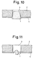
- a plug-type masking member (1) made of material such as a themoplastic foam has been used. Said plug-type masking member (1) is inserted in a hole (3) of an article (2) and then a surface treatment is performed to form a film (4) of said surface treatment as shown in Fig. 10 and after then said plug-type masking member (1) is removed by a hook or by heating to soften and contract said masking member (1) as shown in Fig. 11 (Tokkosho No. 48-29532).
- said plug-type masking members are reciprocally individual and the work to insert said plug-type masking member (1) into holes (3) requires much labor, since the worker must pick up each said plug-type masking member (1) one by one and said work requires much labor and may be troublesome especially in a mass-production continuation process such as the car-manufacturing process.
- the present invention provides a series of connected masking members consisting of a plural number of plug-type unit of single masking members connected reciprocally wherein the connecting parts of said series of connected masking members are snap-off parts and said snap-off parts have a minimum diameter within said series of connected masking members and said minimum diameter is 1/10 to 9/10 of the maximum diameter of said series of connected masking members.
- thermoplastic resin such as polystyrene, polyethylene, polypropylene, polyvinyl chloride, polyamide and the like, a thermosetting resin such as melamine resin, urea resin, phenol resin, epoxy resin and the like, a filler mix containing plastic wherein a filler such as calcium carbonate, talc, bentonite, blast furnace slag, flyash, and the like is mixed in said thermoplastic resin or said thermosetting resin, a foamed plastic of said thermoplastic resin, said thermosetting resin, or said filler mix containing plastic, a fiber material wherein organic fiber, inorganic fiber, pulp and the like is bound by a synthetic resin binder, cork, wood, and the like may be used.
- a thermoplastic resin such as polystyrene, polyethylene, polypropylene, polyvinyl chloride, polyamide and the like
- thermosetting resin such as melamine resin, urea resin, phenol resin, epoxy resin and the like
- a filler mix containing plastic wherein
- a preferable material for said series of conntected masking members of the present invention may be polystyrene foam. since said polystyrene foam is hard and brittle, and the snapping off of one of said connected masking members may be very easy.
- the snapping off of each said connected masking members may be easier.
- press injection molding, cast molding, expansion molding, expansion injection molding may be applied.
- a sticking proof agent such as water-soluble polymer, DFK resin, synthetic resin paint, release agent, silicone, wax, and the like may be coated on the surface of said series of connected masking members to prevent the sticking of a melted masking member to the place where said masking member has been attached.
- the first unit of such a series of masking members at the top is inserted into a hole to be protected by holding said series of connected masking members with a worker's hand, and said first unit of said series of masking members is separated at the top from the second unit of said series of masking members of said series of connected masking members by snapping off the snap-off part between said first unit of said masking members at the top and the second unit of said masking members.
- said first unit of said masking members at the top is attached in said hole and said second unit of said masking members is then situated at the top so that said second unit of said masking members at the top is inserted into another hole and separated by snapping it off from the second next unit of said masking members, the same as for said first unit of said masking members.
- each said unit of said masking members may be easily separated by snapping it off at the correct snapping position and said series of connected masking members may not be broken during transportation, conveyance and handling so that workers can perform masking work very smoothly and the fatigue of such workers may be reduced and therefore, said series of connected masking members may be very suitable for the mass-production continuation process.
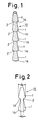
- Figs. 1 to 6 show an embodiment of the present invention
- Figs. 1 to 6 show an embodiment of the present invention.
- (1) is a plug-type unit masking member having a tapering cylinderical shape wherein the lower part of said unit of said masking member has a reverse tapering shape (1)A and a plural number of said units of said masking member (1) (commonly 5 to 20 pieces of said units of said masking member (1) but the number of pieces depends on the size of said units of said masking member) are connected reciprocally and snap-off parts (2) are situated at the connecting part between each said unit of said masking member so that said plural number of units of said masking members are connected reciprocally to form a series of connected masking members (10).
- Fig. 1 is a plug-type unit masking member having a tapering cylinderical shape wherein the lower part of said unit of said masking member has a reverse tapering shape (1)A and a plural number of said units of said masking member (1) (commonly 5 to 20 pieces of said units of said masking member (1) but the number of pieces depends on the size of said units of said mask
- the diameter d1 of said snap-off part (2) is the minimum and supposing that the maximum diameter of one of said plug-type unit masking members (1) is d2 and the relation between d1 and d2 may be 0.9 ⁇ d1 /d2 ⁇ 0.1.
- said series of connected masking members (10) may be snapped off in a suitable length to be easily held with a worker's hand, and for instance, the first plug-type unit of said masking member (1) at the top is inserted into a hole (4) of an article (3) to be protected and then said first unit of each said masking member (1) is separated by snapping it off between said first unit of said masking member (1) and said second unit of said masking member (1) as shown in Fig. 3.
- a surface treatment is carried out on the surface of said article (3) to form a film (5) of said surface treatment as shown in Fig.
- said plug-type unit masking member (1) is made of a thermoplastic foam
- said unit of said masking member (1) may be heated at a higher temperature than the softening point of said thermoplastic foam so as to be softened and at the same time the air and the gas of the blowing agent may come out of said softened masking member (1) so that said masking member (1) may contract as shown in Fig. 5 and in a case where said hole (4) is a bolt hole, when a bolt (6) is attached in said hole (4) as shown in Fig. 6, said contracting masking member (1) may be removed from said hole (4) together with said film (5) covering said hole (4).
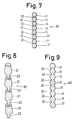
- a series of connected masking members (20) in which a plural number of plug-type units of a masking member (11) having a ball shape are connected reciprocally with intermediating snap-off parts (12) may be provided and said plug-type units of said masking member have various shapes corresponding to the required shape of the hole insofar as the ratio of the diameter d1 of said snap-off part and the maximum diameter d2 is 0.1 to 0.9.
- a series of connected masking members (30) and (40) wherein a plural number of plug-type units of each masking member (1) are connected reciprocally with intermediating snap-off parts (22), (32) having a pole shape may be provided in the present invention.
- said snap-off parts (22), (32) between said plug-type units of each masking member may be more easily snapped off since said snap-off parts (22), (32) have a pole shape.
Landscapes
- Details Or Accessories Of Spraying Plant Or Apparatus (AREA)
- Electroplating Methods And Accessories (AREA)
- Coating Apparatus (AREA)
Applications Claiming Priority (2)
| Application Number | Priority Date | Filing Date | Title |
|---|---|---|---|
| JP1990038707U JPH03128455U (de) | 1990-04-10 | 1990-04-10 | |
| JP38707/90U | 1990-04-10 |
Publications (2)
| Publication Number | Publication Date |
|---|---|
| EP0482202A1 true EP0482202A1 (de) | 1992-04-29 |
| EP0482202A4 EP0482202A4 (en) | 1992-07-08 |
Family
ID=12532791
Family Applications (1)
| Application Number | Title | Priority Date | Filing Date |
|---|---|---|---|
| EP19910906692 Withdrawn EP0482202A4 (en) | 1990-04-10 | 1991-04-09 | Masking material in connected pieces |
Country Status (4)
| Country | Link |
|---|---|
| EP (1) | EP0482202A4 (de) |
| JP (1) | JPH03128455U (de) |
| CA (1) | CA2060516A1 (de) |
| WO (1) | WO1991015304A1 (de) |
Cited By (4)
| Publication number | Priority date | Publication date | Assignee | Title |
|---|---|---|---|---|
| EP0813910A3 (de) * | 1996-06-18 | 1999-06-23 | VOSSCHEMIE GmbH | Schaumstoffstreifen |
| EP0853982A3 (de) * | 1997-01-15 | 2001-12-12 | STAHLSCHMIDT & MAIWORM GmbH | Verfahren und Vorrichtung zum Abdecken von Befestigungslöchern an einem Rad |
| US6413391B1 (en) | 1999-10-29 | 2002-07-02 | Bae Systems Plc | Masking techniques for metal plating |
| EP1998900A4 (de) * | 2006-03-20 | 2010-03-17 | Toerestorps Trad Ab | Abdeckvorrichtung, verfahren zur herstellung der vorrichtung und verwendung davon |
Families Citing this family (1)
| Publication number | Priority date | Publication date | Assignee | Title |
|---|---|---|---|---|
| JP2005046733A (ja) * | 2003-07-29 | 2005-02-24 | Nagoya Oil Chem Co Ltd | 孔部用連結マスキング材 |
Family Cites Families (3)
| Publication number | Priority date | Publication date | Assignee | Title |
|---|---|---|---|---|
| JPH0728944Y2 (ja) * | 1987-06-13 | 1995-07-05 | 名古屋油化株式会社 | 孔部用連結マスキング材 |
| JPH0612878Y2 (ja) * | 1988-04-05 | 1994-04-06 | 名古屋油化株式会社 | 連結マスキング材 |
| JPH0618602Y2 (ja) * | 1988-04-05 | 1994-05-18 | 名古屋油化株式会社 | 連結マスキング材 |
-
1990
- 1990-04-10 JP JP1990038707U patent/JPH03128455U/ja active Pending
-
1991
- 1991-04-09 CA CA002060516A patent/CA2060516A1/en not_active Abandoned
- 1991-04-09 WO PCT/JP1991/000468 patent/WO1991015304A1/ja not_active Ceased
- 1991-04-09 EP EP19910906692 patent/EP0482202A4/en not_active Withdrawn
Non-Patent Citations (2)
| Title |
|---|
| No relevant documents d * |
| See also references of WO9115304A1 * |
Cited By (5)
| Publication number | Priority date | Publication date | Assignee | Title |
|---|---|---|---|---|
| EP0813910A3 (de) * | 1996-06-18 | 1999-06-23 | VOSSCHEMIE GmbH | Schaumstoffstreifen |
| EP0853982A3 (de) * | 1997-01-15 | 2001-12-12 | STAHLSCHMIDT & MAIWORM GmbH | Verfahren und Vorrichtung zum Abdecken von Befestigungslöchern an einem Rad |
| US6413391B1 (en) | 1999-10-29 | 2002-07-02 | Bae Systems Plc | Masking techniques for metal plating |
| US6436266B1 (en) | 1999-10-29 | 2002-08-20 | Bae Systems Plc | Masking techniques for metal plating |
| EP1998900A4 (de) * | 2006-03-20 | 2010-03-17 | Toerestorps Trad Ab | Abdeckvorrichtung, verfahren zur herstellung der vorrichtung und verwendung davon |
Also Published As
| Publication number | Publication date |
|---|---|
| JPH03128455U (de) | 1991-12-25 |
| WO1991015304A1 (en) | 1991-10-17 |
| CA2060516A1 (en) | 1991-10-11 |
| EP0482202A4 (en) | 1992-07-08 |
Similar Documents
| Publication | Publication Date | Title |
|---|---|---|
| US4576664A (en) | Fixing article holders to surfaces | |
| EP0207720B1 (de) | Maske | |
| ATA16093A (de) | Verfahren und vorrichtung zur warmformung und stapelung von hohlen gegenständen mit boden aus einem kunststoffband | |
| EP0287839A3 (de) | Mehrschichtiger Kunststoffbehälter | |
| GB1196655A (en) | Improvements in and relating to Fasteners | |
| EP0368615A1 (de) | Abdeckelement | |
| DE3774356D1 (de) | Granuliertes duengemittel mit einem abbaubaren ueberzug und verfahren zu seiner herstellung. | |
| NL194803B (nl) | Metalen bevestigingsmiddel voorzien van een polymere bekleding en werkwijze voor het vervaardigen daarvan. | |
| DE69328168D1 (de) | Verfahren und vorrichtung zur herstellung eines kunststoffgegenstandes bestehend aus einem gegossenen körper und einer gegossenen beschichtung | |
| DE58908963D1 (de) | Verfahren zur Herstellung von Rohrleitungsteilen aus Kunststoff, anorganischem Füllstoff und Glasfasern im Schleuderguss-Verfahren sowie ein nach diesem Verfahren hergestelltes Rohrleitungsteil. | |
| EP0482202A1 (de) | Maskenmaterial in verbundenen elementen | |
| CA2127658A1 (en) | Conveyable Cover Former and Fastening System | |
| DE60037715D1 (de) | Geformter Artikel aus einer amorphen Legierung, mit gehärteter Oberfläche und Verfahren zu dessen Herstellung | |
| US5277530A (en) | Adhesively secured pump fastener system | |
| US5270085A (en) | Masking member | |
| BR9607278A (pt) | Processos para formar um revestimento de poliuretano sobre um substrato e para preparar um copolímero composiçao de revestimento e artigo moldado ou formado | |
| DE69210537D1 (de) | Artikel mit Form zur Erfassung der Position sowie Verfahren und Vorrichtung zur deren Herstellung und Verarbeitung | |
| DE69732292D1 (de) | Verfahren und vorrichtung zur herstellung von mit thermoplastischem kunststoff beschichteten metallblechen | |
| DE59908038D1 (de) | Vorrichtung und verfahren zur herstellung von faserverstärkten kunststoffen bzw. kunststoffbauteilen nach einem modifizierten rtm-verfahren | |
| SE9302041D0 (sv) | Kardborrefoerband | |
| DE69809649D1 (de) | Behälter mit einer verringerten Menge von aus diesem abgegebenem Azetaldehyd und Verfahren zum Formen desselben | |
| US5193716A (en) | Masking method | |
| EP0367259A1 (de) | Maskenteil | |
| BR8904392A (pt) | Aparelho para pulverizacao de goticulas de adesivo termoplastico sobre um substrato,aparelho para pulverizacao de goticulas de material termoplastico sobre um substrato e processo para pulverizacao de goticulas de adesivo termoplastico | |
| EP0480066A1 (de) | Verfahren zur maskierung |
Legal Events
| Date | Code | Title | Description |
|---|---|---|---|
| PUAI | Public reference made under article 153(3) epc to a published international application that has entered the european phase |
Free format text: ORIGINAL CODE: 0009012 |
|
| 17P | Request for examination filed |
Effective date: 19911211 |
|
| AK | Designated contracting states |
Kind code of ref document: A1 Designated state(s): DE FR GB IT SE |
|
| A4 | Supplementary search report drawn up and despatched |
Effective date: 19920521 |
|
| AK | Designated contracting states |
Kind code of ref document: A4 Designated state(s): DE FR GB IT SE |
|
| 17Q | First examination report despatched |
Effective date: 19940302 |
|
| STAA | Information on the status of an ep patent application or granted ep patent |
Free format text: STATUS: THE APPLICATION IS DEEMED TO BE WITHDRAWN |
|
| 18D | Application deemed to be withdrawn |
Effective date: 19941220 |