EP0482251A1 - Incinérateur - Google Patents
Incinérateur Download PDFInfo
- Publication number
- EP0482251A1 EP0482251A1 EP90311260A EP90311260A EP0482251A1 EP 0482251 A1 EP0482251 A1 EP 0482251A1 EP 90311260 A EP90311260 A EP 90311260A EP 90311260 A EP90311260 A EP 90311260A EP 0482251 A1 EP0482251 A1 EP 0482251A1
- Authority
- EP
- European Patent Office
- Prior art keywords
- reburn
- reburn unit
- coupled
- unit
- outlet opening
- Prior art date
- Legal status (The legal status is an assumption and is not a legal conclusion. Google has not performed a legal analysis and makes no representation as to the accuracy of the status listed.)
- Granted
Links
- 230000006872 improvement Effects 0.000 title claims description 18
- 238000002485 combustion reaction Methods 0.000 claims abstract description 86
- 239000000446 fuel Substances 0.000 claims abstract description 26
- 229930195733 hydrocarbon Natural products 0.000 claims abstract description 24
- 150000002430 hydrocarbons Chemical class 0.000 claims abstract description 24
- 239000007787 solid Substances 0.000 claims abstract description 20
- 239000007789 gas Substances 0.000 claims description 69
- 239000002956 ash Substances 0.000 claims description 47
- 235000002918 Fraxinus excelsior Nutrition 0.000 claims description 31
- QVGXLLKOCUKJST-UHFFFAOYSA-N atomic oxygen Chemical compound [O] QVGXLLKOCUKJST-UHFFFAOYSA-N 0.000 claims description 30
- 239000001301 oxygen Substances 0.000 claims description 30
- 229910052760 oxygen Inorganic materials 0.000 claims description 30
- 239000012530 fluid Substances 0.000 claims description 29
- XLYOFNOQVPJJNP-UHFFFAOYSA-N water Substances O XLYOFNOQVPJJNP-UHFFFAOYSA-N 0.000 claims description 28
- 239000003517 fume Substances 0.000 claims description 25
- 230000033001 locomotion Effects 0.000 claims description 23
- 238000000034 method Methods 0.000 claims description 21
- 230000001706 oxygenating effect Effects 0.000 claims description 20
- 238000004891 communication Methods 0.000 claims description 18
- 239000004215 Carbon black (E152) Substances 0.000 claims description 11
- 239000000463 material Substances 0.000 claims description 11
- 239000007788 liquid Substances 0.000 claims description 8
- 230000007613 environmental effect Effects 0.000 claims description 7
- 238000005260 corrosion Methods 0.000 claims description 5
- 230000007797 corrosion Effects 0.000 claims description 5
- 230000009970 fire resistant effect Effects 0.000 claims description 3
- 238000001035 drying Methods 0.000 abstract description 3
- 230000014759 maintenance of location Effects 0.000 abstract description 3
- 230000009977 dual effect Effects 0.000 abstract description 2
- 230000007246 mechanism Effects 0.000 description 22
- 230000006378 damage Effects 0.000 description 8
- 230000008878 coupling Effects 0.000 description 5
- 238000010168 coupling process Methods 0.000 description 5
- 238000005859 coupling reaction Methods 0.000 description 5
- 230000000694 effects Effects 0.000 description 5
- 238000001816 cooling Methods 0.000 description 4
- 230000006870 function Effects 0.000 description 4
- 239000000203 mixture Substances 0.000 description 4
- 230000008901 benefit Effects 0.000 description 3
- 238000011161 development Methods 0.000 description 3
- 230000018109 developmental process Effects 0.000 description 3
- 230000009286 beneficial effect Effects 0.000 description 2
- 230000002939 deleterious effect Effects 0.000 description 2
- 238000010438 heat treatment Methods 0.000 description 2
- 239000012528 membrane Substances 0.000 description 2
- 230000008569 process Effects 0.000 description 2
- 230000009467 reduction Effects 0.000 description 2
- 239000002699 waste material Substances 0.000 description 2
- 240000007594 Oryza sativa Species 0.000 description 1
- 235000007164 Oryza sativa Nutrition 0.000 description 1
- 238000005299 abrasion Methods 0.000 description 1
- 230000009471 action Effects 0.000 description 1
- 230000004888 barrier function Effects 0.000 description 1
- 230000033228 biological regulation Effects 0.000 description 1
- 230000000903 blocking effect Effects 0.000 description 1
- 239000011248 coating agent Substances 0.000 description 1
- 238000000576 coating method Methods 0.000 description 1
- 239000000567 combustion gas Substances 0.000 description 1
- 238000010276 construction Methods 0.000 description 1
- 238000013016 damping Methods 0.000 description 1
- 238000005202 decontamination Methods 0.000 description 1
- 230000003588 decontaminative effect Effects 0.000 description 1
- 238000010586 diagram Methods 0.000 description 1
- 230000005611 electricity Effects 0.000 description 1
- 238000003912 environmental pollution Methods 0.000 description 1
- 238000011049 filling Methods 0.000 description 1
- 238000009434 installation Methods 0.000 description 1
- 238000012423 maintenance Methods 0.000 description 1
- 239000002184 metal Substances 0.000 description 1
- 238000002156 mixing Methods 0.000 description 1
- 238000012986 modification Methods 0.000 description 1
- 230000004048 modification Effects 0.000 description 1
- 239000002245 particle Substances 0.000 description 1
- 239000004033 plastic Substances 0.000 description 1
- 229920003023 plastic Polymers 0.000 description 1
- 238000003825 pressing Methods 0.000 description 1
- 238000012545 processing Methods 0.000 description 1
- 238000011084 recovery Methods 0.000 description 1
- 230000008439 repair process Effects 0.000 description 1
- 230000004044 response Effects 0.000 description 1
- 230000000979 retarding effect Effects 0.000 description 1
- 235000009566 rice Nutrition 0.000 description 1
- 230000000630 rising effect Effects 0.000 description 1
- 239000000126 substance Substances 0.000 description 1
- 238000012546 transfer Methods 0.000 description 1
- 210000005239 tubule Anatomy 0.000 description 1
- 238000010792 warming Methods 0.000 description 1
Images


Classifications
-
- F—MECHANICAL ENGINEERING; LIGHTING; HEATING; WEAPONS; BLASTING
- F23—COMBUSTION APPARATUS; COMBUSTION PROCESSES
- F23H—GRATES; CLEANING OR RAKING GRATES
- F23H3/00—Grates with hollow bars
- F23H3/02—Grates with hollow bars internally cooled
-
- F—MECHANICAL ENGINEERING; LIGHTING; HEATING; WEAPONS; BLASTING
- F23—COMBUSTION APPARATUS; COMBUSTION PROCESSES
- F23G—CREMATION FURNACES; CONSUMING WASTE PRODUCTS BY COMBUSTION
- F23G7/00—Incinerators or other apparatus for consuming industrial waste, e.g. chemicals
-
- F—MECHANICAL ENGINEERING; LIGHTING; HEATING; WEAPONS; BLASTING
- F23—COMBUSTION APPARATUS; COMBUSTION PROCESSES
- F23G—CREMATION FURNACES; CONSUMING WASTE PRODUCTS BY COMBUSTION
- F23G5/00—Incineration of waste; Incinerator constructions; Details, accessories or control therefor
- F23G5/08—Incineration of waste; Incinerator constructions; Details, accessories or control therefor having supplementary heating
- F23G5/14—Incineration of waste; Incinerator constructions; Details, accessories or control therefor having supplementary heating including secondary combustion
- F23G5/16—Incineration of waste; Incinerator constructions; Details, accessories or control therefor having supplementary heating including secondary combustion in a separate combustion chamber
- F23G5/165—Incineration of waste; Incinerator constructions; Details, accessories or control therefor having supplementary heating including secondary combustion in a separate combustion chamber arranged at a different level
-
- F—MECHANICAL ENGINEERING; LIGHTING; HEATING; WEAPONS; BLASTING
- F23—COMBUSTION APPARATUS; COMBUSTION PROCESSES
- F23G—CREMATION FURNACES; CONSUMING WASTE PRODUCTS BY COMBUSTION
- F23G5/00—Incineration of waste; Incinerator constructions; Details, accessories or control therefor
- F23G5/44—Details; Accessories
- F23G5/46—Recuperation of heat
-
- F—MECHANICAL ENGINEERING; LIGHTING; HEATING; WEAPONS; BLASTING
- F23—COMBUSTION APPARATUS; COMBUSTION PROCESSES
- F23G—CREMATION FURNACES; CONSUMING WASTE PRODUCTS BY COMBUSTION
- F23G5/00—Incineration of waste; Incinerator constructions; Details, accessories or control therefor
- F23G5/50—Control or safety arrangements
-
- F—MECHANICAL ENGINEERING; LIGHTING; HEATING; WEAPONS; BLASTING
- F23—COMBUSTION APPARATUS; COMBUSTION PROCESSES
- F23G—CREMATION FURNACES; CONSUMING WASTE PRODUCTS BY COMBUSTION
- F23G7/00—Incinerators or other apparatus for consuming industrial waste, e.g. chemicals
- F23G7/06—Incinerators or other apparatus for consuming industrial waste, e.g. chemicals of waste gases or noxious gases, e.g. exhaust gases
- F23G7/061—Incinerators or other apparatus for consuming industrial waste, e.g. chemicals of waste gases or noxious gases, e.g. exhaust gases with supplementary heating
- F23G7/065—Incinerators or other apparatus for consuming industrial waste, e.g. chemicals of waste gases or noxious gases, e.g. exhaust gases with supplementary heating using gaseous or liquid fuel
-
- F—MECHANICAL ENGINEERING; LIGHTING; HEATING; WEAPONS; BLASTING
- F23—COMBUSTION APPARATUS; COMBUSTION PROCESSES
- F23J—REMOVAL OR TREATMENT OF COMBUSTION PRODUCTS OR COMBUSTION RESIDUES; FLUES
- F23J1/00—Removing ash, clinker, or slag from combustion chambers
- F23J1/02—Apparatus for removing ash, clinker, or slag from ash-pits, e.g. by employing trucks or conveyors, by employing suction devices
-
- F—MECHANICAL ENGINEERING; LIGHTING; HEATING; WEAPONS; BLASTING
- F23—COMBUSTION APPARATUS; COMBUSTION PROCESSES
- F23L—SUPPLYING AIR OR NON-COMBUSTIBLE LIQUIDS OR GASES TO COMBUSTION APPARATUS IN GENERAL ; VALVES OR DAMPERS SPECIALLY ADAPTED FOR CONTROLLING AIR SUPPLY OR DRAUGHT IN COMBUSTION APPARATUS; INDUCING DRAUGHT IN COMBUSTION APPARATUS; TOPS FOR CHIMNEYS OR VENTILATING SHAFTS; TERMINALS FOR FLUES
- F23L1/00—Passages or apertures for delivering primary air for combustion
- F23L1/02—Passages or apertures for delivering primary air for combustion by discharging the air below the fire
-
- F—MECHANICAL ENGINEERING; LIGHTING; HEATING; WEAPONS; BLASTING
- F23—COMBUSTION APPARATUS; COMBUSTION PROCESSES
- F23M—CASINGS, LININGS, WALLS OR DOORS SPECIALLY ADAPTED FOR COMBUSTION CHAMBERS, e.g. FIREBRIDGES; DEVICES FOR DEFLECTING AIR, FLAMES OR COMBUSTION PRODUCTS IN COMBUSTION CHAMBERS; SAFETY ARRANGEMENTS SPECIALLY ADAPTED FOR COMBUSTION APPARATUS; DETAILS OF COMBUSTION CHAMBERS, NOT OTHERWISE PROVIDED FOR
- F23M5/00—Casings; Linings; Walls
- F23M5/08—Cooling thereof; Tube walls
-
- F—MECHANICAL ENGINEERING; LIGHTING; HEATING; WEAPONS; BLASTING
- F23—COMBUSTION APPARATUS; COMBUSTION PROCESSES
- F23M—CASINGS, LININGS, WALLS OR DOORS SPECIALLY ADAPTED FOR COMBUSTION CHAMBERS, e.g. FIREBRIDGES; DEVICES FOR DEFLECTING AIR, FLAMES OR COMBUSTION PRODUCTS IN COMBUSTION CHAMBERS; SAFETY ARRANGEMENTS SPECIALLY ADAPTED FOR COMBUSTION APPARATUS; DETAILS OF COMBUSTION CHAMBERS, NOT OTHERWISE PROVIDED FOR
- F23M9/00—Baffles or deflectors for air or combustion products; Flame shields
- F23M9/04—Baffles or deflectors for air or combustion products; Flame shields with air supply passages in the baffle or shield
-
- F—MECHANICAL ENGINEERING; LIGHTING; HEATING; WEAPONS; BLASTING
- F23—COMBUSTION APPARATUS; COMBUSTION PROCESSES
- F23M—CASINGS, LININGS, WALLS OR DOORS SPECIALLY ADAPTED FOR COMBUSTION CHAMBERS, e.g. FIREBRIDGES; DEVICES FOR DEFLECTING AIR, FLAMES OR COMBUSTION PRODUCTS IN COMBUSTION CHAMBERS; SAFETY ARRANGEMENTS SPECIALLY ADAPTED FOR COMBUSTION APPARATUS; DETAILS OF COMBUSTION CHAMBERS, NOT OTHERWISE PROVIDED FOR
- F23M9/00—Baffles or deflectors for air or combustion products; Flame shields
- F23M9/06—Baffles or deflectors for air or combustion products; Flame shields in fire-boxes
-
- F—MECHANICAL ENGINEERING; LIGHTING; HEATING; WEAPONS; BLASTING
- F23—COMBUSTION APPARATUS; COMBUSTION PROCESSES
- F23G—CREMATION FURNACES; CONSUMING WASTE PRODUCTS BY COMBUSTION
- F23G2203/00—Furnace arrangements
- F23G2203/107—Furnace arrangements with vibrating grate
-
- F—MECHANICAL ENGINEERING; LIGHTING; HEATING; WEAPONS; BLASTING
- F23—COMBUSTION APPARATUS; COMBUSTION PROCESSES
- F23G—CREMATION FURNACES; CONSUMING WASTE PRODUCTS BY COMBUSTION
- F23G2203/00—Furnace arrangements
- F23G2203/40—Stationary bed furnace
- F23G2203/401—Stationary bed furnace with support for a grate or perforated plate
-
- F—MECHANICAL ENGINEERING; LIGHTING; HEATING; WEAPONS; BLASTING
- F23—COMBUSTION APPARATUS; COMBUSTION PROCESSES
- F23G—CREMATION FURNACES; CONSUMING WASTE PRODUCTS BY COMBUSTION
- F23G2207/00—Control
- F23G2207/10—Arrangement of sensing devices
- F23G2207/101—Arrangement of sensing devices for temperature
-
- F—MECHANICAL ENGINEERING; LIGHTING; HEATING; WEAPONS; BLASTING
- F23—COMBUSTION APPARATUS; COMBUSTION PROCESSES
- F23G—CREMATION FURNACES; CONSUMING WASTE PRODUCTS BY COMBUSTION
- F23G2207/00—Control
- F23G2207/30—Oxidant supply
-
- F—MECHANICAL ENGINEERING; LIGHTING; HEATING; WEAPONS; BLASTING
- F23—COMBUSTION APPARATUS; COMBUSTION PROCESSES
- F23G—CREMATION FURNACES; CONSUMING WASTE PRODUCTS BY COMBUSTION
- F23G2207/00—Control
- F23G2207/60—Additives supply
Definitions
- Austrian patent 317,401 to Bent Faurholdt published on August 26, 1974, introduces air into a reburn tunnel through a pipe placed on the middle of that tunnel itself.
- Faurholdt suggests no use for his pipe other than introducing the air into the tunnel.
- introducing the air through perforations in the pipe results in a "T" configuration for the velocity components of the gases. This may even result in the air thus introduce resisting the flow of gases through the reburn tunnel.
- the present invention provides additional improvements to an incinerator system that will increase its efficiency.
- the system will have the ability to reach operating temperatures prior to the introduction to refuse and with the expenditure of only minimal amounts of auxiliary fuel.
- the developments provide greater ease in the utilization of an incinerator system.
- a fume burning system improves the environmental quality of a gaseous fluid emanating from the output of some source. That source will contain combustible hydrocarbons.
- the fume burning system should include a reburn unit having an inlet opening coupled to and in fluid communication with the output of the source of the fluid.
- the reburn unit also includes an outlet opening for the egress of the gaseous products of combustion from it. Additionally, it should have a burner, coupled to the unit, which burns the fuel inside of the reburn unit. This has the purpose of maintaining the temperature at a level that insures the complete burning of the combustible hydrocarbons.
- the reburn unit includes oxygenating means coupled to it. This component introduces an oxygen-containing gas into the reburn unit to support combustion.
- One improvement of this type of a fume burner involves splitting the reburn unit itself into first and second reburn sections. Basically, they each represent a twin of the other and either can accomplish the functions without the other operating at all.
- the inlet opening to the reburn unit includes first and second inlet ports coupled to and in fluid communication with the output of the hydrocarbon source.
- the first and second inlet ports open into the first and second reburn sections respectively.
- the outlet opening includes first and second outlet ports. These represent the outlets for the first and second reburn sections, respectively.
- the burner and the oxygenating means each includes first and second sections.
- the first section for these two components couples to the first reburn section while the second section of these components couples to the second reburn section.
- the burner section and the oxygenating means performs their functions of burning a fuel and introducing the oxygen-containing gas.
- the reburn unit may include an excitor placed within, surrounded by, and coupled to the reburn unit.
- the excitor as a minimal purpose, in effect reduces the cross-sectional area through which the oxygen-containing gas must travel to reach the combustible hydrocarbons. Furthermore, it provides a reflective surface which will permit the heat either entering or generated within the reburn unit to reach the gaseous molecules to further encourage complete combustion.
- the excitor has the purpose of reducing the cross-sectional area on planes transverse to the path passing from the inlet opening to the outlet opening of the reburn unit.
- the excitor in this configuration, may serve to introduce the oxygen-containing gas into the reburn unit. It does so with nozzles, in fluid communication with the oxygenating mechanism and having an arrangement on the surface of the excitor.
- the nozzles introduce the air into the space between the inner surface of the reburn unit and the excitor and does so at a nonperpendicular angle to the direction of the path from the inlet to the outlet of the excitor.
- the excitor need not introduce the air or other oxygen-containing gas into the reburn unit to have an important and useful function. It may remain passively within the reburn unit to reflect the heat generated or introduced there. This will maintain the gases at an elevated temperature in which they will undergo their efficient and thorough combustion. To accomplish this, the surface of the excitor facing the interior of the reburn should have a composition of a heat and corrosion resistant material. This precludes its destruction at the temperatures and in the gaseous environments at which the reburn unit operates.
- the excitor should not absorb and pass the heat from the reburn unit into its interior. Rather, it should have a relatively low thermal conductivity to effectuate the reflection of the heat from its surface back into the gases undergoing combustion.
- the surface of the excitor facing the interior of the reburn should have a composition of a material with a thermal conductivity constant k less than about where q is the heat conductivity in Btu/Hr. through a surface of thickness l in inches, area A in square feet, and temperature T in degree F.
- a fume burner when having a low input of gaseous fluid, may operate more efficiently when it permits a lower throughput of gases.
- the fume burner may include a choking device coupled to its outlet opening to selectively reduce the cross-sectional area of this outlet opening. This will retain the gases within the reburn unit for a sufficient period of time to accomplish full combustion even though it has a minimal input. This may also find use upon the initial commencement of operation of the unit after it has cooled down and before introducing refuse. The unit can then reach operating temperature where it avoids environmental pollution. Reversing the damping effect and permitting the return unit's outlet opening to revert to its full size then allows the system's normal operation.
- the components given above may form part of an integrated incinerator system.
- the incinerator system will also include a main combustion chamber having an inlet for the introduction of solid bulk refuse.
- An outlet opening from the main chamber permits the egress of the gaseous products of combustion from there.
- the outlet opening from the main combustion chamber then couples to and displays fluid communication with the inlet opening of the reburn unit.
- the method of burning fumes utilizing twin reburn tunnels involves passing the fumes from an output of a source directly into the inlet openings of first and second reburn sections. To maintain a desired temperature, the process will generally require burning a fuel in these two reburn sections. In order to promote the combustion of the gases, an oxygen-containing gas must be introduced into the reburn sections. Lastly, the gaseous combustion products within the reburn sections pass out through outlet openings.
- a fuel undergoes burning within the reburn unit.
- an oxygen-containing gas must enter the reburn unit to achieve combustion of the hydrocarbons.
- the oxygen-containing gas enters the space between the inner surface of the reburn and the excitor at a nonperpendicular angle relative to the direction of the flow of the gas in that space.
- the gaseous combustion products pass out of the reburn unit.
- the burning of fumes proceeds in a reburn unit as generally indicated above.
- the combustion of fuel in that unit maintains the desired temperature.
- Introducing the oxygen-containing gas permits the combustion of the fumes as required.
- the area of the outlet opening through which the gaseous combustion products pass out of the reburn unit may be selectively reduced in order to maintain the temperature in the unit at the desired level with the addition of minimal or no auxiliary fuel.
- the main incinerator chamber has a grate device located above the floor of the main chamber in close proximity to the inlet opening.
- the grating device should hold the refuse for a limited period of time after its introduction through the inlet opening. Subsequently, the grate device allows the refuse to drop through, while continuing to burn, to the floor of the main chamber.
- auxiliary grate of this fashion may prove propitious for various types of refuse including material having a large content of moisture or with a large amount of high Btu combustibles.
- the retention of the refuse for a brief period of time on the grate allows it to dry before it drops to the chamber floor. Otherwise, maintaining the fire in the desired condition might prove more difficult.
- the method of burning refuse to obtain this advantage involves placing it through an inlet opening into an enclosed main chamber of an incinerator system and, specifically, onto a grate located within the main chamber. A fire-resistant floor sits below the grate. The process continues with the partial burning of the refuse while on the grate.
- the burning of the refuse in the incinerator produces ashes dumped into a pit filled with water.
- the water in fact, provides a seal between the environment on the inside of the incinerator and that of the room on the outside. These ashes must undergo removal from time to time to avoid filling the pit.
- An improved device for removing the ashes from the pit includes first an elongated track having its first end located in proximity to the pit. The second end lies further away and at a higher level than the first end.
- a scooping device moves along the track and displays first and second configurations. In the first configuration, it holds onto the ashes while, in the second, it releases whatever ashes it may be holding.
- An elevator moves the scoop device along the track until it reaches a first position near the first end in the pit. In this position, the scoop itself sits in the water in the pit.
- the elevator can then move the scoop to a second position near the other end of the track. At this location, the scoop sits entirely out of the water of the pit.
- a control device couples to the scoop.
- the controller moves the scoop, when at the first location inside the pit, from the second to the first of the configurations. This allows the scoop to actually grab onto ashes and other debris within the pit.
- the controller When at the second, or elevated, position, the controller causes the scoop to move from the first to the second configurations. As a result, the scoop releases the ashes it may have held. Typically, the ashes will then fall into a bin or truck.
- the removal of the ashes or other debris from the pit commences by moving the scoop downward along the track until it reaches the first end located in proximity to the pit. The downward movement of the scoop then stops.
- the scoop then changes its configuration so that it may retain the debris in the pit. While remaining in the configuration to retain the debris, the scoop moves upward along the track and out of the pit. While out of the pit, the scoop changes from the first to the second configuration in which it drops the ashes at an appropriate location.
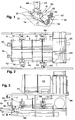
- FIGURE 1 gives a perspective view of an incinerator system installation.
- FIGURE 2 presents a top plan view of a reburn unit having two separate reburn tunnels with each tunnel having two seperate reburn stages.
- FIGURE 3 provides a side elevational view of the reburn unit shown in FIGURE 2 and also shows further stages for processing the exaust gases.
- FIGURE 4 gives a cross-sectional view of the twin reburn tunnels of FIGURE 3 along the line 4-4.
- FIGURE 5 provides a close-up view, partially in section, of the damper that can serve to close off either or even both of the twin reburn tunnels of Figures 1 to 4.
- FIGURE 6 shows the outlet openings of the twin reburn tunnels and the choke dampers which can partially close each of the outlet openings.
- FIGURE 7 illustrates a damper that can serve to close off the inlet opening to either the twin reburn tunnels or partially block the outlet openings.
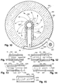
- FIGURE 8 gives a cross-sectional view of a reburn tunnel having an excitor inside where air enters through both the reburn unit's wall and the excitor's wall.
- FIGURE 9 provides a side cross-sectional view of a portion of a reburn tunnel having an excitor inside in which air enters the reburn tunnel through nozzles placed only on the excitor.
- FIGURE 10 gives a cross-sectional view along the line 10-10 of the reburn tunnel shown in FIGURE 9.
- FIGURES 11 to 15 provide diagramatic cross-sectional views of reburn tunnels with excitors showing, in particular, different techniques for increasing the cross-sectional areas of the reburn tunnels in going from the inlet opening to the outlet opening.
- FIGURE 16 gives an isometric view, partially in section, of an incinerator main chamber having a grate in the vicinity of the inlet opening to the chamber but located above the chamber's floor.
- FIGURE 17 displays an end view, in cross section, of the incinerator chamber of FIGURE 16.
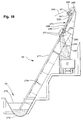
- FIGURE 18 provides a side elevational view of a scoop mechanism for removing ashes from the output pit of an incinerator system.
- FIGURE 19 gives a side elevational view of an ash scoop used in the mechanism of FIGURE 18.
- FIGURE 20 displays a top plan of the scoop of FIGURE 19.
- FIGURE 21 gives an end elevational view along the line 21-21 of the track guide of the scoop of FIGURE 20.
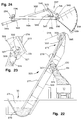
- FIGURE 22 illustrates a side elevational view of yet a further alternate ash removal mechanism.
- FIGURE 23 provides an enlarged view of the chute mechanism shown in FIGURE 22.
- FIGURE 24 gives a side elevational view of an alternate ash removal scoop for use in the mechanisms shown in Figures 18, 22, and 23.
- FIGURE 1 shows an incinerator system generally at 30.
- Bulk refuse or hydrocarbon-containing liquids enters the incinerator 30 through the loader 31 and enters the main chamber 32.
- solid refuse remains upon the pulsating hearth floors 33 and 34.
- the removal mechanism designated generally at 36 lifts it and places it in the truck 37.
- the door 38 permits access to the interior of the main chamber 32 for the usual maintenance.
- the gases produced by the combustion within the main chamber pass through the dual reburn tunnels 41 and 42 and through the further treating, recirculation, and heat removal stages 43. They eventually leave through the stack 44. Heat recovered from the incinerator system 30 may pass into the pipe 45.
- the reburn tunnels 41 and 42 include the respective first reburn stages 51 and 52 and respective second reburn stages 53 and 54.
- the burners 55 and 56 at the beginning of the first stages 51 and 52 maintain the temperatures in the tunnels 41 and 42 at the desired levels for proper operation. They also bring the reburn temperatures up to the proper levels at the each commencement of operation. In fact, environmental regulations often require that the incinerator achieve its operating temperatures prior to the introduction of the first amount of refuse whatsoever after a shut-down.
- the burners 55 and 56 assist in this task.
- the blowers 57 and 58 provide air to the first stages 51 and 52 for combustion and the blowers 59 and 60 perform the same function for the second stages 53 and 54.
- the gases from the second stages 53 and 54 pass through the outlets 63 and 64.
- the second reburn stages 53 and 54 have greater cross-sectional areas than the first reborn stages 51 and 52 of the tunnels 41 and 42, respectively. This allows the second reborn stages 53 and 54 to accommodate the greater volumes of gases resulting from the introduction of air and from the combustion of volitalized hydrocarbons within the tunnels 41 and 42. This represents one method of increasing the volume of the reborn tunnels from their inlets to the outlets. Other techniques accomplishing the same objective receive discussion below with reference to Figures 11 to 15.
- the gases from the main chamber 32 pass through the outlet openings 67 and 68 which also form the inlet openings to the reborn units 41 and 42, respectively.
- the dampers 69 and 70 when in the positions shown in FIGURES 3 to 5, cover the opening 67 and 68, respectively, and close them off. In operation, of course, at least one of the dampers 69 and 70 will remain open. When the main chamber 32 has sufficient combustible material inside, both will open and allow the gases to pass through to the reborn tunnels 41 and 42.
- the dampers 69 and 70 include the axial extensions 71 and 72.
- the lever arms 75 and 76 then connect ridgedly to the extensions 71 and 72.
- the rods 77 and 78 connect the lever arms 75 and 76 to the pistons 79 and 80 which attach ridgedly at their other ends to the brackets 81 and 82.
- the extension of the pistons 79 and 80 in Figures 3 to 5, especially the last, will induce the rotation of the lever arm 76 and its counterpart not shown about the center of the axis 72 to result in the opening of the dampers 69 and 70.
- the counterweights 83 and 84 rotationally coupled to the other ends of the lever arms 75 and 76. They counterbalance the weight of the dampers 69 and 70 and facilitate their controlled motion.
- a significant part of the weight of the dampers 69 and 70 results from their having a covering of the refractory 86 as shown in FIGURE 5. This, of course, provides protection against the high temperatures and corrosiveness of the gases passing around them.
- damper 69 and 70 To help further protect the damper 69 and 70, they include air channels as discussed below with reference to FIGURE 7. The passage of air through the dampers 69 and 70 keeps them at a low enough temperature to prevent their destruction.
- the dampers 91 and 92 cover the outlet opening 63 and 64 of the reburn tunnels 41 and 42, respectively. As shown in FIGURE 6, however, the dampers 91 and 92, even when in the closed position as shown there, only cover up to about a maximum of about 60 percent of the outlet opening 63 and 64. When closed, they retain the gases within the reburn tunnels 41 and 42 for a longer time to assure their complete combustion. Typically such retention becomes desirable when the tunnels 41 and 42, and often, the main chamber 32, operate upon substantially less than the maximum amount of refuse or combustion gases than the system can handle.
- the dampers 91 and 92 operate independently of each other depending upon the conditions in the respective reburn tunnels 41 and 42. They may, for example, submit to the control of temperature sensors placed within their respective tunnels. A lowering temperature may indicate the need to close the appropriate damper to retain the heat within the respective tunnel. Alternately, when the incinerator system produces steam, the damper control may measure the steam pressure produced by the system. A declining steam pressure may indicate a smaller quantity of heat within the system. This would provide an indication that either or both of the dampers 91 and 92 should close at least to some extent.
- the dampers 91 and 92 in FIGURE 6 not only have the totally open or totally closed positions. They may also occupy intermediary locations to effectively block the outputs 63 and 64 by an amount less than the maximum closure that the dampers can achieve.
- the movement of the damper 91 appears in FIGURE 6 under the action of the lever arm 93 connected to the piston 94 which effectuates the desired movement between opening and closing.
- the cable 95 attaches to the damper 91, passes over the pully 97 and connects to the weight 99 to counterbalance the weight of the damper 91. Only the cable 96, the pully 98, and the weight 100 appear in FIGURE 6 for the tunnel 42.
- the choke dampers 91 and 92 serve to retain the gas within the reburn tunnels 41 and 42 for a greater period of time. In other words, it slows down the passage of the gas through these chambers.
- the gas speed should typically not exceed about 55 feet per second. To assure proper combustion, the gas should move no faster than about 46 feet per second.
- the dampers 91 and 92 take the form of rectangular blocks that pivot to open and close. Alternately, as square blocks, they may slide sideways into the position where they partially close the outlet openings 63 and 64. They reopen them by sliding sidewaysin the opposite direction. In fact, they may even slide through an opening in the exterior wall of the incinerator system for this purpose.
- the choke dampers at the ends of the reburn tunnels 41 and 42 may take the form of butterfly valves. This would give them either a round or rectangular configuration located within the outlets of the reburn units. They would then pivot about their centers to partially close or open the reburn's outlets. In the latter configuration, they would remain within the opening but present their edges of minimal area to avoid substantial interference with the passage of the gases.
- FIGURE 7 shows a typical damper, for example, the closure 70 to the outlet opening 68 to the second reburn tunnel 42 seen in FIGURE 5.
- a supply of air passes through the damper 70 to keep its temperature from rising to a point where it could suffer serious damage from the heated environment from which it operates.
- the ends of the axial extensions 72 sit on the outside of the tunnel 42.
- the extensions 72 have hollow interiors which permits the passage of gas through them.
- the flexible tube 104 connects to the nearer axial extension 74 to provide a source of cool gas.
- the cool gas travels through the interior of extension 72 into the axis 106 and out the opening 108 into the chamber 110. It then follows a path created by the dividers 112 and indicated by the arrows 114. Eventually it reaches the opening 116 in the axis 106 where it passes out through the other axial extension 72 and in it to the flexible tube 118.
- FIGURE 18 shows a reburn tunnel generally at 123 which may serve as either of the sections 51 or 53 of the reburn tunnel 41 or the sections 52 and 54 of the reburn tunnel 42.
- the tunnel 123 sits generally on the supports 124 and 125.
- the outer skin 126 surrounds the tunnel 123 and forms the plenum 127 in conjunction with the wall 128.
- the blower 129 places air in the plenum 127 under pressure. From there, the air may pass through the nozzles 130 which take it into the interior 131 of the reburn tunnel 123.
- the refractory 132 covers the interior wall 128 and the nozzles 130 to protect them from the heat and the corrosive environment of the interior 131 of the tunnel 123. Additionally, the air within the plenum 127 may pass through the support 133 and into the excitor 134 located in the tunnel's interior 131. From there it passes through the nozzles 135 and into the interior 131 where it helps support combustion.
- the support 133 itself includes the inner wall 138 generally having a metalic composition.
- the refractory 139 surrounds the wall 138 to protect it from the tunnel's environment.
- the support 133 may have a rectangular cross section on planes parallel to the surface on which the tunnel sits. This will provide it with maximum cross-sectional area for the amount of the interference in the gas flow in the tunnel that it creates.
- the excitor 134 protects its inner metal wall 142 from corrosion and heat damage with the refractory covering 143.
- the nozzles 135 pass through the refractory 143.
- air leaving the nozzles 135 does so with a tangential component of velocity.
- the nozzles 135 make an angle with the radii from the center of the excitor 134. Forty five degrees represents a desirable angle.
- the gas emanating from the nozzles 135 with the tangential component of velocity follows the path generally shown by the arrows 144.
- This tangential movement of the air causes it to efficiently and effectively mix with the combustible gases contained in the tunnel's interior 131.
- the nozzles 135 as well as the outer nozzles 130 will generally introduce the air with an axial component of velocity. In other words, the nozzles point downstream.
- the velocity of the gases leaving the nozzles may in fact make a 45 degree relative to the axial, or downstream, direction.
- the nozzles 135 may appear on the excitor 134 in rows in passing from the inlet to the outlet. To further assist the creation of the desired turbulence within the interior 131, the nozzles may have a staggered configuration from row to row to provide a more even air supply and turbulence.
- FIGURE 8 may undergo modifications for different purposes.
- plugging the nozzles 130 will result in all of the air from the plenum 127 passing around the wall 128, through the support 133, into the excitor 134, and out of the nozzles 135 into the tunnel's interior 131. This appears to have a beneficial effect in creating the turbulence necessary for combustion.
- placing a barrier at the location 145 between the outer wall 126 and the plenum wall 128 will cause the air from the blower 129 to pass around substantially all of the plenum 127 before it reaches the inlet 146 to the support 133. This will have the effect of cooling the wall 128 with the air prior to its introduction into the interior 131. Furthermore, warming the air helps maintain the temperature inside the tunnel 123 at the necessary levels for combustion.
- the excitor 134 may have no nozzles on it whatsoever. In this eventuality, all the air entering the tunnel's interior 131 will pass through the nozzles 130 on the reburn unit 123 itself. Nonetheless, the excitor must still have some air passing through it from one support to the other. This provides a cooling effect to prevent the heat within the reburn tunnel 123 from destroying the excitor 134.
- the excitor 134 serves additional purposes.
- the heat created within the interior 131 of the tunnel 123 itself helps to support the combustion of the gases inside.
- the heat near the middle of the interior 131 will pass into the refractory surface 143 of the excitor 134. From there it will radiate back into the interior 131 where it will help excite combustion.
- the wall of the excitor 134 should permit very little of the heat to pass through.
- it should have a low thermal conductivity constant k, generally less than about 60.
- the conductivity constant k as defined above, will not exceed about 24.
- the air entering the interior 131 must create turbulence in order to accomplish combustion.
- the excitor 134 reduces the maximum dimension of the space in the interior of the tunnel 123.
- air entering the interior 131 has a much shorter distance to travel to reach the combustible gasses.
- it can more effectively create the required turbulence for combustion because of the presence of the excitor 134.
- the space between the outer surface of the refractory 143 of the excitor 134 and the inner surface of the refractory 132 covering the outer wall 128 should remain constant all around the excitor 134. This permits the most efficient mixing and turbulence of the oxygen introduced into the tunnel's interior 131. In the case of a circular reburn tunnel as shown in FIGURE 8, this would result in the interior 131 assuming an annular configuration.
- FIGURE 9 shows generally a portion of a reburn tunnel 153 which may, in fact, represent part of either of the reburn tunnels 41 or 42.
- the outer wall 154 includes the refractory covering 155 but no nozzles passing through it. Rather, all of the air entering the interior 156 of the tunnel 153 passes through the nozzles 157 on the excitor 158. That air, as before, enters the excitor 158 through its supports 159 and 160 and, eventually from the plenum 161. As seen in FIGURE 10, the blower 162 provides the air under pressure which eventually passes through the nozzles 157 into the interior 156.
- the nozzles 157 introduce the air with an axial component of velocity. Stated in other words, the air is introduced at least partially in the direction from the inlet of the reburn section 153 to the outlet, or in the direction from the first support 159 towards the second support 160. As in FIGURE 9, that angle generally amounts to about 45 degrees.
- the nozzles impart a tangential as well as a radial component of velocity to the air passing through them. Again, the nozzles will introduce the air at an angle of about 45 degrees relative to the radial direction. Thus, half of the non-axial velocity of the gases will move them outward and the other half moves them around the interior 156.
- FIGURE 10 where the arrows 166 show the general vorticity to the direction of movement of the air.
- FIGURE 11 gives a diagram of a section of a reborn tunnel having the outer wall 180, the refractory 181 and the two excitor sections 182 and 183.
- the arrow indicates the direction of the gas movement as in FIGURES 12 to 15.
- the excitors 182 and 183 have the same, constant cross-sectional area.
- the cross-sectional area of the interior 184 increases in the direction of the gas movement because the refractory wall 181 slopes outward. This permits the reborn section to accommodate the increasing amounts of air introduced either through the wall 181 or the excitors 182 and 183.
- the cross-sectional area of the interior 184 increases gradually because of the gradual slope of the refractory wall.
- FIGURE 12 appears another reborn section. It too has the outer wall 190 and 191, the refractory 192 and 193, and the excitor sections 194 and 195. As shown there, the interior 196 experiences a sharp, discontinuous increase at the juncture 197. This may, for example, represent the juncture between two separate reborn stages as shown in FIGURES 2 and 3 and discussed above.
- FIGURE 13 again shows a reborn section having the outer wall 200 and 201, refractory sections 202 and 203 and excitor sections 204 and 205.
- the interior volume 206 increases gradually at the juncture 207 between the two sections.
- the sloping wall at the juncture 207 results in less adding another undesired turbulence than the very sharp discontinuity 197 shown in FIGURE 12.
- FIGURE 14 Another reburn section appears in FIGURE 14 and includes the outer wall 210, the refractory 211, and the excitor sections 212 and 213.
- the smaller cross-sectional area of the excitor 213 as compared to the excitor 214 results in an increase in the cross-sectional area 214 of the interior as the gas travels from the excitor 212 to the excitor 213.
- FIGURE 15 shows the reburn section with the walls 220 and 221 and the excitor sections 222 and 223.
- the conic shape of the excitor sections 222 and 223 results in a gradual increase of the volume of the gas as it passes across them in the interior 224.
- the initial combustion of the refuse takes place in the main chamber 32 as seen in Figures 16 and 17.
- the screw feeders 230 may assist in the introduction of particulate refuse such as rice hulls. More typically, bulk refuse enters through the opening 231 in the forewall 232. In any event, the bulk refuse entering the incinerator 32 sits upon the grate generally at 234. It will rest there briefly to permit combustion to commence.
- the refuse may undergo drying while it rests upon the grate 234 to permit its more facile subsequent burning. If, upon enterring, it immediately sat upon the hearth 33, it would experience greater difficulty in drying in order to undergo subsequent combustion.
- a very high Btu content material such as plastics may burn at very high temperatures. If this occurred on the floor 33, the uneven heating could cause slogging of the floor itself.
- the refuse sits upon the grate 234, for a limited period of time.
- the majority of the fixed hydrocarbons within the material should remain unburned when the refuse slips through or off the grate 234 and onto the floor 33.
- the volatile hydrocarbon content may well have, by this time, already entered the gas stream.
- the grate 234 to permit the refuse to fall to the floor 33, will include the holes 235 passing through it.
- the size of the openings of the holes 235 generally lies in the range of 12 to 18 inches This permits most types of refuse to fall through to the floor prior to the burning of the majority of the fixed hydrocarbons.
- the grate 23 of course, exists in the heated and corrosive environment of the main chamber 32. Thus, it should generally have some mechanism for cooling it to prevent its destruction by heat or corrosion.
- the grate 234 includes the hollow longitudinal pipes 236 and 237 and the cross pipes 238.
- the pipe 236 has the couplings 239 and 240 while the pipe 237 includes the couplings 241 and 242. This permits the passage through it of a fluid which will effectuate the cooling of the grate 234.
- the fluid thus introduced may take the form of air, water, steam, or oil.
- the pipes 236 to 238 of the grate 234 will have a refractory coating to provide further heat protection.
- a wear surface composed typically of face hardened refractory will help protect the grate 234 from abrasion due to the refuse placed upon it.
- the floor 33 may assume a number of forms.
- a particular and advanced type of pulsed hearth floor appears in Basic's U. S. Patent 4,475,469 mentioned above.
- Other types of floors may work also, displaying various degrees of desirability.
- the floor 33 may simply be form of a stationary hearth. Some form of a ram or other pusher would then typically move the refuse along until it burned into ashes which would then fall into an appropriate collector. Often, however, the floor will experience some form of movement to assist the burning refuse in traveling from the inlet to the outlet of the main chamber 32.
- the floor 33 may often constitute a hearth, whether moving or stationary.
- the pulsating hearth whether in the configuration shown in Basic's patent or otherwise has proved most efficient.
- the hearth experiences arcuate movement, in pulses, in the direction from the inlet 231 toward the outlet. It moves more rapidly in the former direction than the latter in order to toss the refuse along almost in a snow-shovel type movement.
- the hearth floor 33 shown in FIGURE 16 has a shape that has proved beneficial in the burning of many types of refuse.
- the floor inclines from the inlet 232 to the outlet ash pit 244. This slight lean built into the upper floor 33 and the lower floor 34 assists the refuse in moving in response to any motion experienced by the floors.
- the floors 33 and 34 include the ridges 246 and 247, respectively, on their upper surfaces. This helps channel and shuffle the refuse sitting there to aid in its combustion.
- the jets 248 on the upper floor 33 and 249 on the lower floor 34 provide under-fire air to assist combustion to the burning refuse.
- the nozzles 249 As shown in FIGURE 17, the nozzles 249, as do the nozzles 248 of the upper floor 33, the lower floor 34, incline downwards as they introduce the air into the main chamber 32. This downward angle on the nozzles 249 and 248 helps prevent the entrance of particles of refuse into them which could result in their clogging.
- the amount of air introduced through the nozzles 248 and 249 may vary depending upon the conditions within the incinerator system in general in the main chamber 32 in particular. Thus, as discussed above, the system may contain insufficient refuse to operate at or near capacity. Introducing in this case less air through these jets, may assist the entire incinerator system to reach or remain at its proper operating temperature.
- the main chamber 32 could include a grate floor underneath the grate 234. The refuse would fall from the upper grate to the lower grate and then undergo its full combustion. This lower grate may then either remain stationary or experience some type of movement to transfer the burning refuse in the direction of the ash pit 244.
- the main chamber 32 includes the membrane sidewalls 253 and 254 which appear diagramatically in FIGURES 16 AND 17. In these walls, the water passes through the lower inlet pipes 255 and 256. From there it passes through the tubules 257 and 258 of the membrane walls 253 and 254 to the header pipe 259. From there it may travel elsewhere to provide useful energy in the form of steam for electricity, heating, or other purposes.
- the main chamber may not have sufficient refuse to support the heat throughout the incinerotor system.
- the amount of heat taken out through the header 259 may suffer a reduction in order to leave sufficient heat within the main chamber and reburn tunnels to maintain the temperatures required for clean and efficient burning.
- the ash pit 244 of the main chamber 32 includes the screw feeders 263 and 264. These remove ashes from the pit 244. However, as with other ash removal systems such as the chain drag system, the moving components of the screw feeders 263 and 264 sit under the water and in the ash pit where any repair proves difficult. A significantly improved type of ash removal system appears in FIGURES 18 to 25.
- the ash pit 35 appears at the bottom of FIGURE 18. Typically, it will contain water 271 and the ashes 272 at the bottom.
- the water 271 provides a seal between the interior of the main combustion chamber and the room atmosphere.
- the scoop mechanism shown generally at 273 descends along the track 277 until the scoop 278, in the configuration shown in solid lines in FIGURE 18, enters the water 271 and digs into the ash heap 272. It then reverts to its carrying configuration shown in dashed lines in FIGURE 18 while remaining at the bottom of the pit 272. This allows the scoop 278 to capture a portion of the ashes 272.
- the scoop mechanism 273 then rises along the track 277. Desirably, it will stop shortly after lifting the scoop 278 itself out of the water 271. The water entrained with the ashes 272 will then have an opportunity to drain through the openings 281 in the bottom of the scoop 278. The back of the track 277 forms a trough 278 which will guide the dripping water back into the pit 35.
- the scoop 278 moves from its holding configuration shown in dashed lines to its release configuration shown in solid lines.
- the ashes then fall from the scoop 278 through the opening 282 in the trough 278 and into the truck 37 or other container.
- the side guards 283 keep the ashes from splattering outside of the truck 37.
- the scoop mechanism 273 moves upward and downward under the influence of the cable 284.
- the cable 284 attaches to a typical winch which winds up and releases the cable 284 depending upon the winch's controls.
- the cable 284 passes over the pully 285 and attaches to the scoop mechanism 273.
- the winch unwinds the cable 284, the latter passes over the pulley 285 and allows the scoop mechanism 273 to descend into the pit 35.
- the winch winds up the cable 284, it pulls on the scoop mechanism 273 dragging it out of the water and up the track 277.
- the scoop mechanism, or trolley, 273 appears in greater detail in FIGURES 19 and 20.
- the trolley 273 first consists of the rigid frame formed by the runner bars 288 and 289, and the front crossbar 290 and the rear crossbar 291 rigidly adhered to the runner bars 288 and 289.
- the front wheels 292 and 293 and the rear wheels 294 and 295 ride inside of the track 277 as shown in FIGURE 21.
- the horizontal guide wheels 296 and 297 press against the tracks 277 from the outside of the rear wheels 294 and 295, respectively. This assures proper alignment of the trolley 273 on the track 277.
- the arrangement of the guide wheels 296 and 297 has a further advantage in considering the use of the trolley 273 in removing ashes from the pit 35. Specifically, the rear wheels 294 and 295 riding inside of the track members 277 and the guide wheels 296 and 297 pressing against the side of the track members 277 largely orient the scoop mechanism 273 on the track 277. When the cable 284 allows the scoop 278 to descend into the pit 35, only the front end of the trolley 273 actually enters the water 271. The rear of the trolley 273, including the wheels 294 to 297, remain at all times outside of the water 271.
- the scoop 278 includes the ridgedly attached flange 301 to which the rod 302 pivotally connects at the juncture 303.
- the other end of the rod 302 connects to a piston contained within the cylinder 306.
- the piston 306 in turn pivotally connects to the flanges 307 and 308 on the rear crossbar 291.
- the scoop 278 may contact a solid object in the pit 35. This happens since the incinerator system 30 accepts bulk refuse without presorting. A common item that may find its way into the pit 35 is a muffler or other solid discard. Desirably, the cylinder 306 should not attempt to force the movement of the scoop 278 any further. Thus, in this intermediate configuration, the scoop 278 will remain in contact with the solid object.
- the controls may actually reduce the pressure within the cylinder 306 once the scoop 278 contacts the solid object within the pit 35. This provides additional assurance that the solid object will not damage any component of the ash removal system.
- the fluid for controlling the cylinder 306 passes through the hoses 315 and 316 which in turn wrap around the reel 317.
- the reel 317 releases and recaptures the midportions 319 and 320 of the hoses to keep them out of the way of the trolley 273.
- FIGURE 22 shows the track mechanism generally at 325, but with a slightly different chute mechanism for delivering the ashes into the truck 37.
- the track 277 and the trolley 273 remain virtually the same as before.
- the track 325 includes the rotating chute guide 326 which assumes the configuration shown in FIGURE 22 with the trolley 273 near the top of the track. Then the scoop 278 moves from its retaining to its releasing configuration. When this occurs and the ashes drop from the scoop, the chute guide 326 directd the ashes to the truck 37. After the ashes have entered the truck 37, the chute guide 326 rotates in the counterclockwise direction shown in FIGURE 22 so that its shovel 327 forms a portion of the trough 328.
- FIGURE 23 shows the opposite side of the track 325 from that seen in FIGURE 22.
- the operation of the rotating track portion 327 of the chute 326 results from the influence of the cylinder 330.
- the cylinder 330 forces out its piston, the latter connects to the lever arm 331 rigidly attached to the rotating track portion 327.
- the lever arm 331 will take the position shown in phantom and the track portion 327 will connect with the remaining of the chute 328.
- FIGURE 24 An alternate type of scoop mechanism appearing generally at 337 in FIGURE 24. It utilizes the same trolly as in FIGURES 19 and 20. Thus, it includes the same runner bars 288 and 289 with the crossbars 290 and 291. It moves along the track in the same manner as described previously utilizing the wheels 292 to 297.
- This trolley employs, instead of the scoop 278 shown in the prior figures, the bucket 338 which has the holes 339 for water to pass through.
- the bucket 338 has a rotational coupling at the juncture 292 and the flange 340 which controls its configuration.
- the flange 340 in turn connects to the lever arm 341 which attaches to the usual bar 302.
- the bar 302 connects to a piston within the hydraulic cylinder 339.
- the cylinder 339 in turn, has a pivotal coupling to the flange 340 which must be added to the trolley 273 as of FIGURES 19 and 20.
- the bar 302 at its juncture 303, also couples to the lever arm 346.
- the latter pivotally couples to the flange 347 attached by the braces 348 to the crossbar 290.
- the lever arm 346 thus assures the correct rotational motion of the juncture 303 and, concomitantly, the scooping movement of the bucket 338.
- the trolley 337 then moves up the track 277. Then the cylinder extends the rod 302, and the bucket rotates in the clockwise direction of FIGURE 24 and dumps its contents.
- the back hoe scoop 278 shown in FIGURES 19 and 20 would appear more desirable for the usual municipal waste.
- the scoop 278 may have to stop its motion in the forward direction when contacting a solid object like a muffler or a bicycle.
- the pneumatic cylinder 306 has a greater cushioning to permit the scoop 278 to stop its motion when it makes the contact and yet not destroy either the cylinder 306 or the scoop 278.
- the valving for the cylinder 306 may reduce the pressure should the scoop 278 contact such a solid object. This helps avoid destruction in many of the components of the trolley 273 or the track 277.
- the trolley should include the brackets 345 and 347. Otherwise, switching between the two mechanisms simply involves exchanging the cylinders 306 and 344 and the scoop 278 with the bucket 338. Additionally, the bucket 338 requires the lever arms 341 and 346 while the scoop 278 does not use any such lever arm.
- the ash removal system may employ either type of scoop depending upon the refuse placed into the incinerator.
Landscapes
- Engineering & Computer Science (AREA)
- Mechanical Engineering (AREA)
- General Engineering & Computer Science (AREA)
- Combustion & Propulsion (AREA)
- Chemical & Material Sciences (AREA)
- Environmental & Geological Engineering (AREA)
- Incineration Of Waste (AREA)
- Gasification And Melting Of Waste (AREA)
- Treatment Of Sludge (AREA)
- Processing Of Solid Wastes (AREA)
- Bakery Products And Manufacturing Methods Therefor (AREA)
- Breeding Of Plants And Reproduction By Means Of Culturing (AREA)
- Solid Fuels And Fuel-Associated Substances (AREA)
Priority Applications (17)
| Application Number | Priority Date | Filing Date | Title |
|---|---|---|---|
| AT99101310T ATE299573T1 (de) | 1990-10-15 | 1990-10-15 | Anlage und verfahren zur rauchverbrennung |
| EP99101313A EP0913636B1 (fr) | 1990-10-15 | 1990-10-15 | Dispositif et procédé d'incinération pour déchets en vrac |
| AT99101311T ATE287514T1 (de) | 1990-10-15 | 1990-10-15 | Anlage und verfahren zur rauchverbrennung unter verwendung einer nachverbrennungseinheit mit rauchgasklappe |
| EP99101310A EP0913638B1 (fr) | 1990-10-15 | 1990-10-15 | Système et procédé de combustion des fumées |
| DE69034183T DE69034183T2 (de) | 1990-10-15 | 1990-10-15 | Anlage und Verfahren zur Rauchverbrennung unter Verwendung einer Nachverbrennungseinheit mit Rauchgasklappe |
| DE69034199T DE69034199T2 (de) | 1990-10-15 | 1990-10-15 | Anlage und Verfahren zur Rauchverbrennung |
| EP99101312A EP0922906A3 (fr) | 1990-10-15 | 1990-10-15 | Dispositif pour enlever des débris |
| DE69033225T DE69033225T2 (de) | 1990-10-15 | 1990-10-15 | Müllverbrennungsanlage |
| DK90311260T DK0482251T3 (da) | 1990-10-15 | 1990-10-15 | Forbedringer ved forbrændingsovn |
| ES99101310T ES2248929T3 (es) | 1990-10-15 | 1990-10-15 | Sistema y metodo para el quemado de humos. |
| ES90311260T ES2135378T3 (es) | 1990-10-15 | 1990-10-15 | Incinerador. |
| DK99101310T DK0913638T3 (da) | 1990-10-15 | 1990-10-15 | System og fremgangsmåde til röggasforbrænding |
| EP90311260A EP0482251B1 (fr) | 1981-03-27 | 1990-10-15 | Incinérateur |
| ES99101311T ES2232037T3 (es) | 1990-10-15 | 1990-10-15 | Sistema de quemado de humos y metodo que emplea unidad de requemado con medios de reduccion de flujo. |
| AT90311260T ATE182667T1 (de) | 1990-10-15 | 1990-10-15 | Müllverbrennungsanlage |
| EP99101311A EP0913637B1 (fr) | 1990-10-15 | 1990-10-15 | Dispositif et procédé de combustion des fumées utilisant une chambre de postcombustion équipée d'un dispositif étrangleur |
| GR990402387T GR3031289T3 (en) | 1981-03-27 | 1999-09-22 | Incinerator improvements |
Applications Claiming Priority (2)
| Application Number | Priority Date | Filing Date | Title |
|---|---|---|---|
| US06/248,054 US4438705A (en) | 1981-03-27 | 1981-03-27 | Incinerator with two reburn stages, and, optionally, heat recovery |
| EP90311260A EP0482251B1 (fr) | 1981-03-27 | 1990-10-15 | Incinérateur |
Related Child Applications (4)
| Application Number | Title | Priority Date | Filing Date |
|---|---|---|---|
| EP99101312A Division EP0922906A3 (fr) | 1990-10-15 | 1990-10-15 | Dispositif pour enlever des débris |
| EP99101313A Division EP0913636B1 (fr) | 1990-10-15 | 1990-10-15 | Dispositif et procédé d'incinération pour déchets en vrac |
| EP99101311A Division EP0913637B1 (fr) | 1990-10-15 | 1990-10-15 | Dispositif et procédé de combustion des fumées utilisant une chambre de postcombustion équipée d'un dispositif étrangleur |
| EP99101310A Division EP0913638B1 (fr) | 1990-10-15 | 1990-10-15 | Système et procédé de combustion des fumées |
Publications (2)
| Publication Number | Publication Date |
|---|---|
| EP0482251A1 true EP0482251A1 (fr) | 1992-04-29 |
| EP0482251B1 EP0482251B1 (fr) | 1999-07-28 |
Family
ID=22937470
Family Applications (6)
| Application Number | Title | Priority Date | Filing Date |
|---|---|---|---|
| EP86116254A Expired - Lifetime EP0235370B1 (fr) | 1981-03-27 | 1982-03-24 | Système d'incinération |
| EP82102435A Expired EP0064589B1 (fr) | 1981-03-27 | 1982-03-24 | Incinérateur avec deux étages pour la combustion retardée et la récupération de chaleur, facultativement |
| EP86116252A Expired - Lifetime EP0235369B1 (fr) | 1981-03-27 | 1982-03-24 | Système de combustion des fumées |
| EP86116251A Withdrawn EP0235368A1 (fr) | 1981-03-27 | 1982-03-24 | Foyer pour incinérateur |
| EP86116253A Withdrawn EP0234005A1 (fr) | 1981-03-27 | 1982-03-24 | Chambre de combustion |
| EP90311260A Expired - Lifetime EP0482251B1 (fr) | 1981-03-27 | 1990-10-15 | Incinérateur |
Family Applications Before (5)
| Application Number | Title | Priority Date | Filing Date |
|---|---|---|---|
| EP86116254A Expired - Lifetime EP0235370B1 (fr) | 1981-03-27 | 1982-03-24 | Système d'incinération |
| EP82102435A Expired EP0064589B1 (fr) | 1981-03-27 | 1982-03-24 | Incinérateur avec deux étages pour la combustion retardée et la récupération de chaleur, facultativement |
| EP86116252A Expired - Lifetime EP0235369B1 (fr) | 1981-03-27 | 1982-03-24 | Système de combustion des fumées |
| EP86116251A Withdrawn EP0235368A1 (fr) | 1981-03-27 | 1982-03-24 | Foyer pour incinérateur |
| EP86116253A Withdrawn EP0234005A1 (fr) | 1981-03-27 | 1982-03-24 | Chambre de combustion |
Country Status (13)
| Country | Link |
|---|---|
| US (1) | US4438705A (fr) |
| EP (6) | EP0235370B1 (fr) |
| JP (7) | JPH0665925B2 (fr) |
| KR (1) | KR880002409B1 (fr) |
| AT (2) | ATE59896T1 (fr) |
| AU (1) | AU562529B2 (fr) |
| CA (1) | CA1183728A (fr) |
| DE (2) | DE3280291D1 (fr) |
| DK (1) | DK172931B1 (fr) |
| GR (1) | GR3031289T3 (fr) |
| IE (1) | IE56016B1 (fr) |
| NO (1) | NO159043C (fr) |
| NZ (1) | NZ200041A (fr) |
Cited By (2)
| Publication number | Priority date | Publication date | Assignee | Title |
|---|---|---|---|---|
| EP0509774A3 (en) * | 1991-04-15 | 1993-02-03 | John N. Basic Sr. | Incinerator improvements |
| EP1983261A1 (fr) * | 2007-04-20 | 2008-10-22 | Ernst Schenkel | Compensateur de mouvement |
Families Citing this family (48)
| Publication number | Priority date | Publication date | Assignee | Title |
|---|---|---|---|---|
| US4475469A (en) * | 1981-03-27 | 1984-10-09 | Basic J N Sen | Pulsating incinerator hearth |
| DE3245846C2 (de) * | 1981-12-28 | 1986-05-28 | Mitsubishi Denki K.K., Tokio/Tokyo | Sicherheitsvorrichtung für ein chirurgisches Laserstrahlgerät |
| DE3312863C2 (de) * | 1983-04-09 | 1986-12-04 | Kernforschungsanlage Jülich GmbH, 5170 Jülich | Brennkammer zum Verbrennen von Abgasen |
| JPS61246514A (ja) * | 1985-04-22 | 1986-11-01 | Tsurumi Gosei Rozai Kk | 金属スクラツプ中の可燃性物質の焼却除去装置 |
| JPS6246117A (ja) * | 1985-08-20 | 1987-02-28 | Tsurumi Gosei Rozai Kk | ガス化燃焼による金属回収方法及び金属回収用ガス化燃焼装置 |
| JPS62129614A (ja) * | 1985-11-29 | 1987-06-11 | Nippon Nenshiyou Syst Kk | 低圧力・低発熱量ガスの燃焼装置 |
| JPS62147210A (ja) * | 1985-12-20 | 1987-07-01 | Matsushita Electric Works Ltd | 焼却炉 |
| JPS635238U (fr) * | 1986-06-25 | 1988-01-14 | ||
| JPS63105309A (ja) * | 1986-10-21 | 1988-05-10 | Seinan Kogyo Kk | 廃プラスチツク専焼炉 |
| JPS63273717A (ja) * | 1987-04-30 | 1988-11-10 | Kurimoto Iron Works Ltd | 粗大ごみ焼却処理装置 |
| JP3504901B2 (ja) | 1987-06-01 | 2004-03-08 | ワールドワイド・パテント・ライセンシング・カンパニー・エル・エル・シー | 煙霧燃焼システム |
| JPS6414515A (en) * | 1987-07-08 | 1989-01-18 | Kurimoto Ltd | Incinerating disposer for plastic series waste |
| JPH063295B2 (ja) * | 1987-09-30 | 1994-01-12 | シャープ株式会社 | ごみ処理機 |
| JPH0547942Y2 (fr) * | 1987-10-27 | 1993-12-17 | ||
| FR2625294B1 (fr) * | 1987-12-23 | 1990-08-17 | Fondis Sa | Procede de postcombustion amelioree des imbrules et moyens pour le mettre en oeuvre dans un appareil de chauffage |
| JPH0612344Y2 (ja) * | 1988-05-13 | 1994-03-30 | シャープ株式会社 | 生ごみ焼却炉 |
| US4870910A (en) * | 1989-01-25 | 1989-10-03 | John Zink Company | Waste incineration method and apparatus |
| US5370066A (en) * | 1989-09-21 | 1994-12-06 | Phoenix Environmental, Ltd. | Method for making solid waste material environmentally safe using heat |
| US5230292A (en) * | 1989-09-21 | 1993-07-27 | Phoenix Environmental, Ltd. | Apparatus for making solid waste material environmentally safe using heat |
| US5127347A (en) * | 1989-09-21 | 1992-07-07 | Phoenix Environmental, Ltd. | Method and apparatus for the reduction of solid waste material using coherent radiation |
| US5065680A (en) * | 1989-09-21 | 1991-11-19 | Phoenix Environmental, Ltd. | Method and apparatus for making solid waste material environmentally safe using heat |
| US5199363A (en) * | 1989-09-21 | 1993-04-06 | Phoenix Environmental, Ltd. | Method and apparatus for making solid waste material environmentally safe using heat |
| JP3133769B2 (ja) | 1990-12-28 | 2001-02-13 | ワールドワイド・パテント・ライセンシング・カンパニー・エル・エル・シー | 焼却システムの改良 |
| US5161471A (en) * | 1991-11-13 | 1992-11-10 | Riley Stoker Corporation | Apparatus for reburning ash material of a previously burned primary fuel |
| US5152232A (en) * | 1992-01-06 | 1992-10-06 | Crawford James P | Incinerator apparatus |
| US5976488A (en) * | 1992-07-02 | 1999-11-02 | Phoenix Environmental, Ltd. | Process of making a compound having a spinel structure |
| US5353719A (en) * | 1992-12-09 | 1994-10-11 | Eshleman Roger D | Apparatus and method for controlled processing of materials |
| US5730072A (en) * | 1995-10-17 | 1998-03-24 | Advanced Envirotech Systems, Inc. | Method and system for continuous rapid incineration of solid waste in an oxygen-rich environment |
| US5890442A (en) * | 1996-01-23 | 1999-04-06 | Mcdermott Technology, Inc. | Gas stabilized reburning for NOx control |
| US5769010A (en) * | 1996-02-01 | 1998-06-23 | Btu International, Inc. | Furnace including localized incineration of effluents |
| US6055916A (en) * | 1998-05-08 | 2000-05-02 | Stevers; Paul H. | Waste material processing apparatus and method |
| US5934892A (en) | 1998-08-06 | 1999-08-10 | Institute Of Gas Technology | Process and apparatus for emissions reduction using partial oxidation of combustible material |
| CA2374593C (fr) | 1999-05-21 | 2009-02-17 | Barlow Projects, Inc. | Systeme de combustion de carburant ameliore |
| US20050072342A1 (en) * | 2003-01-29 | 2005-04-07 | Basic John N. | Incinerator seals |
| US6932002B2 (en) * | 2003-09-04 | 2005-08-23 | Recycling Solutions Technology, Llc | System and method of processing solid waste |
| US20050211143A1 (en) * | 2003-09-04 | 2005-09-29 | Recycling Solutions Technology, Llc | System and method of generating electricity |
| WO2006056053A1 (fr) * | 2004-11-23 | 2006-06-01 | Kenneth Davison | Procede et appareil de gazeification de materiaux organiques solides a l'aide d'un systeme d'elimination de cendres a alimentation laterale/centrale |
| ITRM20050260A1 (it) * | 2005-05-25 | 2005-08-24 | Luca Bidolli | Dispositivo per bruciare combustibili liquidi gassificati. |
| US7743717B2 (en) * | 2006-12-08 | 2010-06-29 | Plasma Waste Recycling, Inc. | Apparatus for conveying solid waste to a furnace |
| JP2008190808A (ja) * | 2007-02-06 | 2008-08-21 | Soai:Kk | 燃焼装置 |
| US20090114861A1 (en) * | 2007-09-12 | 2009-05-07 | Paul Luebbers | Control system for dynamic orifice valve apparatus and method |
| JP5141171B2 (ja) * | 2007-10-05 | 2013-02-13 | 三浦工業株式会社 | ボイラ |
| WO2010106538A1 (fr) * | 2009-03-17 | 2010-09-23 | T.D.E. Recovery Technologies Ltd. | Réacteur de pyrolyse |
| US20120240831A1 (en) * | 2011-03-22 | 2012-09-27 | Guilherme Martins Ferreira | System and Process for the Combustion of Solid Fuels |
| US9784447B1 (en) * | 2012-01-23 | 2017-10-10 | II Paul N Ohunna | Flexible universal flue pipe connector with damper and sweep access (connector with damper and access) |
| US9175786B2 (en) | 2013-08-30 | 2015-11-03 | Lumec Control Products, Inc. | Valve apparatus |
| US10697713B2 (en) * | 2014-07-02 | 2020-06-30 | Trane International Inc. | Gas-fired tube swaged joint |
| CN108224463A (zh) * | 2018-02-23 | 2018-06-29 | 铁岭众缘环保设备制造有限公司 | 一种捆状秸秆锅炉的推料机构 |
Citations (5)
| Publication number | Priority date | Publication date | Assignee | Title |
|---|---|---|---|---|
| US3190244A (en) * | 1960-12-19 | 1965-06-22 | Gordon H Hoskinson | Incinerator and smoke-consuming apparatus |
| US3702756A (en) * | 1971-01-06 | 1972-11-14 | Vernon D Bowman | Smokeless antitoxic burner apparatus |
| US3797415A (en) * | 1972-10-30 | 1974-03-19 | J Young | Incinerator with a plurality of outer walls and a hollow grate |
| US4635569A (en) * | 1986-03-28 | 1987-01-13 | Irving Domnitch | Incinerator system arrangement with dual scrubbing chambers |
| US4856438A (en) * | 1988-03-14 | 1989-08-15 | Dean Peugh | Furnace |
Family Cites Families (30)
| Publication number | Priority date | Publication date | Assignee | Title |
|---|---|---|---|---|
| US1957921A (en) * | 1930-12-15 | 1934-05-08 | John C White | Furnace |
| GB686590A (en) * | 1948-08-20 | 1953-01-28 | Fr De Const Mecaniques Soc | Improved shaking grate for boilers and other heating devices |
| FR1178501A (fr) * | 1956-07-06 | 1959-05-12 | Stein & Roubaix | Four à atmosphère, à sole oscillante pour le transport des articles dans le four |
| US2965051A (en) * | 1959-04-20 | 1960-12-20 | Kocee James | Trash burner |
| US3489109A (en) * | 1968-07-09 | 1970-01-13 | Waste Combustion Corp | Apparatus for burning combustible products in exhaust gases and removing fly ash therefrom |
| US3610179A (en) * | 1970-02-27 | 1971-10-05 | Alexander Shaw Jr | Incinerator |
| AU1757270A (en) * | 1970-04-15 | 1972-01-20 | Kumakichi Sugano | Incinerator |
| AT317401B (de) * | 1970-04-28 | 1974-08-26 | Faurholdt Bent | Verbrennungsofen für die Verbrennung von Kunststoffmaterialien |
| US3680501A (en) * | 1970-07-08 | 1972-08-01 | Modern Pollution Control Inc | Incinerator |
| US3658482A (en) * | 1970-09-08 | 1972-04-25 | College Research Corp | Afterburner |
| AU2096770A (en) * | 1970-10-12 | 1972-04-13 | Evirontech Corporation | Multipurpose furnace with smoke afterburner |
| JPS4821472U (fr) * | 1971-07-19 | 1973-03-10 | ||
| US3792671A (en) * | 1972-05-17 | 1974-02-19 | Clean Air Ator Corp | Incinerator with afterburner |
| DE2227614A1 (de) * | 1972-06-07 | 1973-12-20 | Froeling Kessel Behaelterappar | Abfallverbrennungsanlage mit nachverbrennungskammer |
| JPS514598B2 (fr) * | 1972-07-11 | 1976-02-13 | ||
| US3844233A (en) * | 1973-08-09 | 1974-10-29 | Consumat Syst | Directional control of hot gases from an incinerator or the like |
| US3863756A (en) * | 1973-08-23 | 1975-02-04 | R J Reynolds Company | Reciprocating conveyor |
| US3822651A (en) * | 1973-09-04 | 1974-07-09 | D Harris | Water cooled kiln for waste disposal |
| JPS50138669A (fr) * | 1974-04-20 | 1975-11-05 | ||
| US3875874A (en) * | 1974-05-28 | 1975-04-08 | Berton G Altmann | Device for combustion of gaseous wastes |
| JPS5212783A (en) * | 1975-07-21 | 1977-01-31 | Chikara Kogyo Kk | Furnace generatin super heated steam |
| US3995568A (en) * | 1975-11-12 | 1976-12-07 | Miro Dvirka | Incinerator and combustion air system therefor |
| JPS54112574A (en) * | 1978-02-23 | 1979-09-03 | Daito Sanshin Co Ltd | Air inhibition combustion type waste incinerator |
| JPS5520358A (en) * | 1978-07-31 | 1980-02-13 | Hitachi Metals Ltd | Incinerator |
| US4246850A (en) * | 1979-03-16 | 1981-01-27 | Trecan Limited | Incinerator |
| JPS5618534U (fr) * | 1979-07-18 | 1981-02-18 | ||
| US4270467A (en) * | 1980-01-14 | 1981-06-02 | Enertherm, Inc. | Low mass flow waste fuel incinerator |
| JPS56142315A (en) * | 1980-04-03 | 1981-11-06 | Toshio Oyamada | Incinerator |
| DE3072145D1 (en) * | 1980-09-01 | 1989-04-20 | Zink Co John | Disposal of oxides of nitrogen and heat recovery in a single self-contained structure |
| US4317417A (en) * | 1981-01-02 | 1982-03-02 | Samuel Foresto | Incinerator apparatus and method of utilizing the cleaned waste gases thereof |
-
1981
- 1981-03-27 US US06/248,054 patent/US4438705A/en not_active Expired - Lifetime
-
1982
- 1982-03-17 NZ NZ200041A patent/NZ200041A/en unknown
- 1982-03-22 CA CA000398937A patent/CA1183728A/fr not_active Expired
- 1982-03-24 DE DE8686116254T patent/DE3280291D1/de not_active Expired - Lifetime
- 1982-03-24 EP EP86116254A patent/EP0235370B1/fr not_active Expired - Lifetime
- 1982-03-24 AT AT86116252T patent/ATE59896T1/de active
- 1982-03-24 EP EP82102435A patent/EP0064589B1/fr not_active Expired
- 1982-03-24 DE DE8686116252T patent/DE3280290D1/de not_active Expired - Lifetime
- 1982-03-24 AT AT86116254T patent/ATE59895T1/de not_active IP Right Cessation
- 1982-03-24 EP EP86116252A patent/EP0235369B1/fr not_active Expired - Lifetime
- 1982-03-24 EP EP86116251A patent/EP0235368A1/fr not_active Withdrawn
- 1982-03-24 EP EP86116253A patent/EP0234005A1/fr not_active Withdrawn
- 1982-03-25 DK DK198201363A patent/DK172931B1/da not_active IP Right Cessation
- 1982-03-25 IE IE708/82A patent/IE56016B1/en unknown
- 1982-03-26 NO NO821030A patent/NO159043C/no not_active IP Right Cessation
- 1982-03-26 KR KR8201310A patent/KR880002409B1/ko not_active Expired
- 1982-03-27 JP JP57048172A patent/JPH0665925B2/ja not_active Expired - Lifetime
-
1984
- 1984-08-15 AU AU31916/84A patent/AU562529B2/en not_active Expired
-
1990
- 1990-03-26 JP JP2076567A patent/JPH0363408A/ja active Granted
- 1990-10-15 EP EP90311260A patent/EP0482251B1/fr not_active Expired - Lifetime
-
1992
- 1992-05-06 JP JP4140983A patent/JPH0759969B2/ja not_active Expired - Lifetime
- 1992-12-25 JP JP4357808A patent/JP2528426B2/ja not_active Expired - Lifetime
-
1994
- 1994-02-28 JP JP6054499A patent/JP2525726B2/ja not_active Expired - Lifetime
- 1994-02-28 JP JP6054497A patent/JP2525725B2/ja not_active Expired - Lifetime
- 1994-02-28 JP JP6054498A patent/JPH0759968B2/ja not_active Expired - Lifetime
-
1999
- 1999-09-22 GR GR990402387T patent/GR3031289T3/el unknown
Patent Citations (5)
| Publication number | Priority date | Publication date | Assignee | Title |
|---|---|---|---|---|
| US3190244A (en) * | 1960-12-19 | 1965-06-22 | Gordon H Hoskinson | Incinerator and smoke-consuming apparatus |
| US3702756A (en) * | 1971-01-06 | 1972-11-14 | Vernon D Bowman | Smokeless antitoxic burner apparatus |
| US3797415A (en) * | 1972-10-30 | 1974-03-19 | J Young | Incinerator with a plurality of outer walls and a hollow grate |
| US4635569A (en) * | 1986-03-28 | 1987-01-13 | Irving Domnitch | Incinerator system arrangement with dual scrubbing chambers |
| US4856438A (en) * | 1988-03-14 | 1989-08-15 | Dean Peugh | Furnace |
Cited By (3)
| Publication number | Priority date | Publication date | Assignee | Title |
|---|---|---|---|---|
| EP0509774A3 (en) * | 1991-04-15 | 1993-02-03 | John N. Basic Sr. | Incinerator improvements |
| EP1434004A3 (fr) * | 1991-04-15 | 2004-07-07 | John N. Basic Sr. | Incinérateur |
| EP1983261A1 (fr) * | 2007-04-20 | 2008-10-22 | Ernst Schenkel | Compensateur de mouvement |
Also Published As
Similar Documents
| Publication | Publication Date | Title |
|---|---|---|
| EP0482251A1 (fr) | Incinérateur | |
| US5209169A (en) | Incinerator improvements | |
| US5413715A (en) | Incinerator improvements | |
| US5007353A (en) | Incinerator improvements | |
| EP0913638B1 (fr) | Système et procédé de combustion des fumées | |
| AU649933B2 (en) | Incinerator improvements | |
| AU661232B2 (en) | Incinerator improvements | |
| AU677376B2 (en) | Incinerator improvements | |
| AU667625B2 (en) | Incinerator improvements | |
| AU677809B2 (en) | Incinerator improvements | |
| IE903646A1 (en) | Incinerator improvements | |
| NZ314563A (en) | Removing ashes from pit beneath furnace, scoop moves on track between pit and raised discharge position | |
| HK1067692A (en) | Incinerator improvements | |
| IE20000398A1 (en) | Fume Burning System and Method | |
| IE20000400A1 (en) | Incinerator System and Method for Bulk Refuse | |
| HK1020769A (en) | Device and method for removing debris | |
| JP3365985B2 (ja) | 水を含む灰をピットから除去する装置及び方法 | |
| IE20000399A1 (en) | Device and Method for removing Debris | |
| JP3504901B2 (ja) | 煙霧燃焼システム | |
| JP3133769B2 (ja) | 焼却システムの改良 | |
| JP3476452B2 (ja) | 水分を含む灰をピットから除去する装置および水分を含む廃物をピットから除去する方法 | |
| KR0173305B1 (ko) | 개선된 소각로 시스템 | |
| JP2000154909A (ja) | ばらごみ及び炭化水素含有液用焼却システム及びごみ焼却法 |
Legal Events
| Date | Code | Title | Description |
|---|---|---|---|
| PUAI | Public reference made under article 153(3) epc to a published international application that has entered the european phase |
Free format text: ORIGINAL CODE: 0009012 |
|
| AK | Designated contracting states |
Kind code of ref document: A1 Designated state(s): AT BE CH DE DK ES FR GB GR IT LI LU NL SE |
|
| 17P | Request for examination filed |
Effective date: 19921002 |
|
| 17Q | First examination report despatched |
Effective date: 19930607 |
|
| GRAG | Despatch of communication of intention to grant |
Free format text: ORIGINAL CODE: EPIDOS AGRA |
|
| RAP1 | Party data changed (applicant data changed or rights of an application transferred) |
Owner name: BASIC, JOHN N. SR. |
|
| GRAG | Despatch of communication of intention to grant |
Free format text: ORIGINAL CODE: EPIDOS AGRA |
|
| GRAH | Despatch of communication of intention to grant a patent |
Free format text: ORIGINAL CODE: EPIDOS IGRA |
|
| GRAH | Despatch of communication of intention to grant a patent |
Free format text: ORIGINAL CODE: EPIDOS IGRA |
|
| GRAA | (expected) grant |
Free format text: ORIGINAL CODE: 0009210 |
|
| AK | Designated contracting states |
Kind code of ref document: B1 Designated state(s): AT BE CH DE DK ES FR GB GR IT LI LU NL SE |
|
| REF | Corresponds to: |
Ref document number: 182667 Country of ref document: AT Date of ref document: 19990815 Kind code of ref document: T |
|
| REG | Reference to a national code |
Ref country code: CH Ref legal event code: EP |
|
| ITF | It: translation for a ep patent filed | ||
| REG | Reference to a national code |
Ref country code: CH Ref legal event code: NV Representative=s name: KIRKER & CIE SA |
|
| REF | Corresponds to: |
Ref document number: 69033225 Country of ref document: DE Date of ref document: 19990902 |
|
| ET | Fr: translation filed | ||
| REG | Reference to a national code |
Ref country code: ES Ref legal event code: FG2A Ref document number: 2135378 Country of ref document: ES Kind code of ref document: T3 |
|
| REG | Reference to a national code |
Ref country code: DK Ref legal event code: T3 |
|
| PLBE | No opposition filed within time limit |
Free format text: ORIGINAL CODE: 0009261 |
|
| STAA | Information on the status of an ep patent application or granted ep patent |
Free format text: STATUS: NO OPPOSITION FILED WITHIN TIME LIMIT |
|
| 26N | No opposition filed | ||
| REG | Reference to a national code |
Ref country code: GB Ref legal event code: IF02 |
|
| PGFP | Annual fee paid to national office [announced via postgrant information from national office to epo] |
Ref country code: GR Payment date: 20040924 Year of fee payment: 15 |
|
| PGFP | Annual fee paid to national office [announced via postgrant information from national office to epo] |
Ref country code: NL Payment date: 20041003 Year of fee payment: 15 |
|
| PGFP | Annual fee paid to national office [announced via postgrant information from national office to epo] |
Ref country code: SE Payment date: 20041006 Year of fee payment: 15 |
|
| PGFP | Annual fee paid to national office [announced via postgrant information from national office to epo] |
Ref country code: DE Payment date: 20041007 Year of fee payment: 15 |
|
| PGFP | Annual fee paid to national office [announced via postgrant information from national office to epo] |
Ref country code: FR Payment date: 20041008 Year of fee payment: 15 |
|
| PGFP | Annual fee paid to national office [announced via postgrant information from national office to epo] |
Ref country code: GB Payment date: 20041013 Year of fee payment: 15 Ref country code: AT Payment date: 20041013 Year of fee payment: 15 Ref country code: LU Payment date: 20041013 Year of fee payment: 15 |
|
| PGFP | Annual fee paid to national office [announced via postgrant information from national office to epo] |
Ref country code: DK Payment date: 20041014 Year of fee payment: 15 |
|
| PGFP | Annual fee paid to national office [announced via postgrant information from national office to epo] |
Ref country code: CH Payment date: 20041015 Year of fee payment: 15 |
|
| PGFP | Annual fee paid to national office [announced via postgrant information from national office to epo] |
Ref country code: ES Payment date: 20041116 Year of fee payment: 15 |
|
| PGFP | Annual fee paid to national office [announced via postgrant information from national office to epo] |
Ref country code: BE Payment date: 20041215 Year of fee payment: 15 |
|
| PG25 | Lapsed in a contracting state [announced via postgrant information from national office to epo] |
Ref country code: GB Free format text: LAPSE BECAUSE OF NON-PAYMENT OF DUE FEES Effective date: 20051015 Ref country code: AT Free format text: LAPSE BECAUSE OF NON-PAYMENT OF DUE FEES Effective date: 20051015 Ref country code: IT Free format text: LAPSE BECAUSE OF NON-PAYMENT OF DUE FEES;WARNING: LAPSES OF ITALIAN PATENTS WITH EFFECTIVE DATE BEFORE 2007 MAY HAVE OCCURRED AT ANY TIME BEFORE 2007. THE CORRECT EFFECTIVE DATE MAY BE DIFFERENT FROM THE ONE RECORDED. Effective date: 20051015 |
|
| PG25 | Lapsed in a contracting state [announced via postgrant information from national office to epo] |
Ref country code: SE Free format text: LAPSE BECAUSE OF NON-PAYMENT OF DUE FEES Effective date: 20051016 |
|
| PG25 | Lapsed in a contracting state [announced via postgrant information from national office to epo] |
Ref country code: ES Free format text: LAPSE BECAUSE OF NON-PAYMENT OF DUE FEES Effective date: 20051017 |
|
| PG25 | Lapsed in a contracting state [announced via postgrant information from national office to epo] |
Ref country code: DK Free format text: LAPSE BECAUSE OF NON-PAYMENT OF DUE FEES Effective date: 20051031 Ref country code: LI Free format text: LAPSE BECAUSE OF NON-PAYMENT OF DUE FEES Effective date: 20051031 Ref country code: LU Free format text: LAPSE BECAUSE OF NON-PAYMENT OF DUE FEES Effective date: 20051031 Ref country code: BE Free format text: LAPSE BECAUSE OF NON-PAYMENT OF DUE FEES Effective date: 20051031 Ref country code: CH Free format text: LAPSE BECAUSE OF NON-PAYMENT OF DUE FEES Effective date: 20051031 |
|
| PG25 | Lapsed in a contracting state [announced via postgrant information from national office to epo] |
Ref country code: NL Free format text: LAPSE BECAUSE OF NON-PAYMENT OF DUE FEES Effective date: 20060501 |
|
| PG25 | Lapsed in a contracting state [announced via postgrant information from national office to epo] |
Ref country code: DE Free format text: LAPSE BECAUSE OF NON-PAYMENT OF DUE FEES Effective date: 20060503 |
|
| REG | Reference to a national code |
Ref country code: DK Ref legal event code: EBP |
|
| REG | Reference to a national code |
Ref country code: CH Ref legal event code: PL |
|
| EUG | Se: european patent has lapsed | ||
| GBPC | Gb: european patent ceased through non-payment of renewal fee |
Effective date: 20051015 |
|
| PG25 | Lapsed in a contracting state [announced via postgrant information from national office to epo] |
Ref country code: FR Free format text: LAPSE BECAUSE OF NON-PAYMENT OF DUE FEES Effective date: 20060630 |
|
| NLV4 | Nl: lapsed or anulled due to non-payment of the annual fee |
Effective date: 20060501 |
|
| REG | Reference to a national code |
Ref country code: FR Ref legal event code: ST Effective date: 20060630 |
|
| REG | Reference to a national code |
Ref country code: ES Ref legal event code: FD2A Effective date: 20051017 |
|
| BERE | Be: lapsed |
Owner name: *BASIC JOHN N. SR. Effective date: 20051031 |
|
| PG25 | Lapsed in a contracting state [announced via postgrant information from national office to epo] |
Ref country code: GR Free format text: LAPSE BECAUSE OF NON-PAYMENT OF DUE FEES Effective date: 19990728 |