EP0482251B1 - Müllverbrennungsanlage - Google Patents
Müllverbrennungsanlage Download PDFInfo
- Publication number
- EP0482251B1 EP0482251B1 EP90311260A EP90311260A EP0482251B1 EP 0482251 B1 EP0482251 B1 EP 0482251B1 EP 90311260 A EP90311260 A EP 90311260A EP 90311260 A EP90311260 A EP 90311260A EP 0482251 B1 EP0482251 B1 EP 0482251B1
- Authority
- EP
- European Patent Office
- Prior art keywords
- reburn
- sections
- excitor
- incinerator
- outlet
- Prior art date
- Legal status (The legal status is an assumption and is not a legal conclusion. Google has not performed a legal analysis and makes no representation as to the accuracy of the status listed.)
- Expired - Lifetime
Links
Images


Classifications
-
- F—MECHANICAL ENGINEERING; LIGHTING; HEATING; WEAPONS; BLASTING
- F23—COMBUSTION APPARATUS; COMBUSTION PROCESSES
- F23G—CREMATION FURNACES; CONSUMING WASTE PRODUCTS BY COMBUSTION
- F23G7/00—Incinerators or other apparatus for consuming industrial waste, e.g. chemicals
-
- F—MECHANICAL ENGINEERING; LIGHTING; HEATING; WEAPONS; BLASTING
- F23—COMBUSTION APPARATUS; COMBUSTION PROCESSES
- F23H—GRATES; CLEANING OR RAKING GRATES
- F23H3/00—Grates with hollow bars
- F23H3/02—Grates with hollow bars internally cooled
-
- F—MECHANICAL ENGINEERING; LIGHTING; HEATING; WEAPONS; BLASTING
- F23—COMBUSTION APPARATUS; COMBUSTION PROCESSES
- F23G—CREMATION FURNACES; CONSUMING WASTE PRODUCTS BY COMBUSTION
- F23G5/00—Incineration of waste; Incinerator constructions; Details, accessories or control therefor
- F23G5/08—Incineration of waste; Incinerator constructions; Details, accessories or control therefor having supplementary heating
- F23G5/14—Incineration of waste; Incinerator constructions; Details, accessories or control therefor having supplementary heating including secondary combustion
- F23G5/16—Incineration of waste; Incinerator constructions; Details, accessories or control therefor having supplementary heating including secondary combustion in a separate combustion chamber
- F23G5/165—Incineration of waste; Incinerator constructions; Details, accessories or control therefor having supplementary heating including secondary combustion in a separate combustion chamber arranged at a different level
-
- F—MECHANICAL ENGINEERING; LIGHTING; HEATING; WEAPONS; BLASTING
- F23—COMBUSTION APPARATUS; COMBUSTION PROCESSES
- F23G—CREMATION FURNACES; CONSUMING WASTE PRODUCTS BY COMBUSTION
- F23G5/00—Incineration of waste; Incinerator constructions; Details, accessories or control therefor
- F23G5/44—Details; Accessories
-
- F—MECHANICAL ENGINEERING; LIGHTING; HEATING; WEAPONS; BLASTING
- F23—COMBUSTION APPARATUS; COMBUSTION PROCESSES
- F23G—CREMATION FURNACES; CONSUMING WASTE PRODUCTS BY COMBUSTION
- F23G5/00—Incineration of waste; Incinerator constructions; Details, accessories or control therefor
- F23G5/44—Details; Accessories
- F23G5/46—Recuperation of heat
-
- F—MECHANICAL ENGINEERING; LIGHTING; HEATING; WEAPONS; BLASTING
- F23—COMBUSTION APPARATUS; COMBUSTION PROCESSES
- F23G—CREMATION FURNACES; CONSUMING WASTE PRODUCTS BY COMBUSTION
- F23G5/00—Incineration of waste; Incinerator constructions; Details, accessories or control therefor
- F23G5/50—Control or safety arrangements
-
- F—MECHANICAL ENGINEERING; LIGHTING; HEATING; WEAPONS; BLASTING
- F23—COMBUSTION APPARATUS; COMBUSTION PROCESSES
- F23G—CREMATION FURNACES; CONSUMING WASTE PRODUCTS BY COMBUSTION
- F23G7/00—Incinerators or other apparatus for consuming industrial waste, e.g. chemicals
- F23G7/06—Incinerators or other apparatus for consuming industrial waste, e.g. chemicals of waste gases or noxious gases, e.g. exhaust gases
- F23G7/061—Incinerators or other apparatus for consuming industrial waste, e.g. chemicals of waste gases or noxious gases, e.g. exhaust gases with supplementary heating
- F23G7/065—Incinerators or other apparatus for consuming industrial waste, e.g. chemicals of waste gases or noxious gases, e.g. exhaust gases with supplementary heating using gaseous or liquid fuel
-
- F—MECHANICAL ENGINEERING; LIGHTING; HEATING; WEAPONS; BLASTING
- F23—COMBUSTION APPARATUS; COMBUSTION PROCESSES
- F23J—REMOVAL OR TREATMENT OF COMBUSTION PRODUCTS OR COMBUSTION RESIDUES; FLUES
- F23J1/00—Removing ash, clinker, or slag from combustion chambers
- F23J1/02—Apparatus for removing ash, clinker, or slag from ash-pits, e.g. by employing trucks or conveyors, by employing suction devices
-
- F—MECHANICAL ENGINEERING; LIGHTING; HEATING; WEAPONS; BLASTING
- F23—COMBUSTION APPARATUS; COMBUSTION PROCESSES
- F23L—SUPPLYING AIR OR NON-COMBUSTIBLE LIQUIDS OR GASES TO COMBUSTION APPARATUS IN GENERAL ; VALVES OR DAMPERS SPECIALLY ADAPTED FOR CONTROLLING AIR SUPPLY OR DRAUGHT IN COMBUSTION APPARATUS; INDUCING DRAUGHT IN COMBUSTION APPARATUS; TOPS FOR CHIMNEYS OR VENTILATING SHAFTS; TERMINALS FOR FLUES
- F23L1/00—Passages or apertures for delivering primary air for combustion
- F23L1/02—Passages or apertures for delivering primary air for combustion by discharging the air below the fire
-
- F—MECHANICAL ENGINEERING; LIGHTING; HEATING; WEAPONS; BLASTING
- F23—COMBUSTION APPARATUS; COMBUSTION PROCESSES
- F23M—CASINGS, LININGS, WALLS OR DOORS SPECIALLY ADAPTED FOR COMBUSTION CHAMBERS, e.g. FIREBRIDGES; DEVICES FOR DEFLECTING AIR, FLAMES OR COMBUSTION PRODUCTS IN COMBUSTION CHAMBERS; SAFETY ARRANGEMENTS SPECIALLY ADAPTED FOR COMBUSTION APPARATUS; DETAILS OF COMBUSTION CHAMBERS, NOT OTHERWISE PROVIDED FOR
- F23M5/00—Casings; Linings; Walls
- F23M5/08—Cooling thereof; Tube walls
-
- F—MECHANICAL ENGINEERING; LIGHTING; HEATING; WEAPONS; BLASTING
- F23—COMBUSTION APPARATUS; COMBUSTION PROCESSES
- F23M—CASINGS, LININGS, WALLS OR DOORS SPECIALLY ADAPTED FOR COMBUSTION CHAMBERS, e.g. FIREBRIDGES; DEVICES FOR DEFLECTING AIR, FLAMES OR COMBUSTION PRODUCTS IN COMBUSTION CHAMBERS; SAFETY ARRANGEMENTS SPECIALLY ADAPTED FOR COMBUSTION APPARATUS; DETAILS OF COMBUSTION CHAMBERS, NOT OTHERWISE PROVIDED FOR
- F23M9/00—Baffles or deflectors for air or combustion products; Flame shields
- F23M9/04—Baffles or deflectors for air or combustion products; Flame shields with air supply passages in the baffle or shield
-
- F—MECHANICAL ENGINEERING; LIGHTING; HEATING; WEAPONS; BLASTING
- F23—COMBUSTION APPARATUS; COMBUSTION PROCESSES
- F23M—CASINGS, LININGS, WALLS OR DOORS SPECIALLY ADAPTED FOR COMBUSTION CHAMBERS, e.g. FIREBRIDGES; DEVICES FOR DEFLECTING AIR, FLAMES OR COMBUSTION PRODUCTS IN COMBUSTION CHAMBERS; SAFETY ARRANGEMENTS SPECIALLY ADAPTED FOR COMBUSTION APPARATUS; DETAILS OF COMBUSTION CHAMBERS, NOT OTHERWISE PROVIDED FOR
- F23M9/00—Baffles or deflectors for air or combustion products; Flame shields
- F23M9/06—Baffles or deflectors for air or combustion products; Flame shields in fire-boxes
-
- F—MECHANICAL ENGINEERING; LIGHTING; HEATING; WEAPONS; BLASTING
- F23—COMBUSTION APPARATUS; COMBUSTION PROCESSES
- F23G—CREMATION FURNACES; CONSUMING WASTE PRODUCTS BY COMBUSTION
- F23G2203/00—Furnace arrangements
- F23G2203/107—Furnace arrangements with vibrating grate
-
- F—MECHANICAL ENGINEERING; LIGHTING; HEATING; WEAPONS; BLASTING
- F23—COMBUSTION APPARATUS; COMBUSTION PROCESSES
- F23G—CREMATION FURNACES; CONSUMING WASTE PRODUCTS BY COMBUSTION
- F23G2203/00—Furnace arrangements
- F23G2203/40—Stationary bed furnace
- F23G2203/401—Stationary bed furnace with support for a grate or perforated plate
-
- F—MECHANICAL ENGINEERING; LIGHTING; HEATING; WEAPONS; BLASTING
- F23—COMBUSTION APPARATUS; COMBUSTION PROCESSES
- F23G—CREMATION FURNACES; CONSUMING WASTE PRODUCTS BY COMBUSTION
- F23G2207/00—Control
- F23G2207/10—Arrangement of sensing devices
- F23G2207/101—Arrangement of sensing devices for temperature
-
- F—MECHANICAL ENGINEERING; LIGHTING; HEATING; WEAPONS; BLASTING
- F23—COMBUSTION APPARATUS; COMBUSTION PROCESSES
- F23G—CREMATION FURNACES; CONSUMING WASTE PRODUCTS BY COMBUSTION
- F23G2207/00—Control
- F23G2207/30—Oxidant supply
-
- F—MECHANICAL ENGINEERING; LIGHTING; HEATING; WEAPONS; BLASTING
- F23—COMBUSTION APPARATUS; COMBUSTION PROCESSES
- F23G—CREMATION FURNACES; CONSUMING WASTE PRODUCTS BY COMBUSTION
- F23G2207/00—Control
- F23G2207/60—Additives supply
Definitions
- Basic's US-A-4,475,469 discloses, in conjunction with the above two patents, an improved hearth floor which moves under the influence of impulses to urge the burning debris along from the inlet of the main chamber to the ash outlet.
- This pulsating hearth developed by Basic represents a significant improvement on the major advances disclosed in his two incinerator patents referenced above.
- AT-A-317,401 suggests introducing air into a reburn tunnel through a pipe placed on the middle of that tunnel itself.
- the patent suggests no use for the pipe other than for introducing the air into the tunnel.
- introducing the air through perforations in the pipe results in a "T" configuration for the velocity components of the gases. This may even result in the air thus introduce resisting the flow of gases through the reburn tunnel.
- US-A-3190244 suggests use of a reburn unit with two reburn sections in association with a main combustion chamber.
- the present invention provides an incinerator system having the features of the preamble of claim 1 characterised in that damper means are provided in the outlet ports the damper means being independently operable so that one of the outlet ports may be closed to fluid flow whilst the other outlet port remains open to fluid flow.
- the reburn unit may include an excitor placed within, surrounded by, and coupled to the reburn unit.
- the excitor as a minimal purpose, in effect reduces the cross-sectional area through which the oxygen-containing gas must travel to reach the combustible hydro-carbons. Furthermore, it provides a reflective surface which will permit the heat either entering or generated with the reburn unit to reach the gaseous molecules to further encourage complete combustion.
- the excitor has the purpose of reducing the cross-sectional area on planes transverse to the path passing from the inlet opening to the outlet opening of the reburn unit.
- the excitor in this configuration, may serve to introduce the oxygen-containing gas into the reburn unit. It does so with nozzles, in fluid communication with the oxygenating mechanism and having an arrangement on the surface of the excitor.
- the nozzles introduce the air into the space between the inner surface of the reburn unit and the excitor and does so at a nonperpendicular angle to the direction of the path from the inlet to the outlet of the excitor.
- the excitor need not introduce the air or other oxygen-containing gas into the reburn unit to have an important and useful function. It may remain passively within the reburn unit to reflect the heat generated or introduced there. This will maintain the gases at an elevated temperature in which they will undergo their efficient and thorough combustion. To accomplish this, the surface of the excitor facing the interior of the reburn should have a composition of a heat and corrosion resistant material. This precludes its destruction at the temperatures and in the gaseous environments at which the reburn unit operates.
- the excitor should not absorb and pass the heat from the reburn unit into its interior. Rather, it should have a relatively low thermal conductivity to effectuate the reflection of the heat from its surface back into the gases undergoing combustion.
- the surface of the excitor facing the interior of the reburn should have a composition of a material with a thermal conductivity constant k less than about 60 British thermal unit inch per square foot hour degree Fahrenheit (8.65 Watt per metre kelvin) and is preferably less than 24 British thermal unit inch per square foot hour degree Fahrenheit (3.46 Watt per metre kelvin).
- reburn unit when having a low input of refuse may operate more efficiently when it permits a lower throughput of gases.
- reburn unit may include a choking device coupled to its outlet opening to selectively reduce the cross-section area of this outlet opening. This will retain the gases within the reburn unit for a sufficient period of time to accomplish full combustion even though it has a minimal input. This may also find use upon the initial commencement of operation of the unit after it has cooled down and before introducing refuse. The unit can then reach operating temperature where it avoids environmental pollution. Reversing the damping effect and permitting the return unit's outlet opening to revert to its full size then allows the system's normal operation.
- FIGURE 1 give a perspective view of an incinerator system installation.
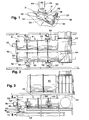
- FIGURE 2 presents a top plan view of a reburn unit having two separate reburn tunnels with each tunnel having two separate reburn stages.
- FIGURE 3 provides a side elevational view of the reburn unit shown in FIGURE 2 and also shows further stages for processing the exaust gases.
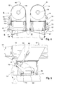
- FIGURE 4 gives a cross-sectional view of the twin reburn tunnels of FIGURE 3 along the line 4-4.
- FIGURE 5 provides a close-up view, partially in section, of the damper that can serve to close off either or even both of the twin reburn tunnels of Figures 1 to 4.
- FIGURE 6 shows the outlet openings of the twin reburn tunnels and the choke dampers which can partially close each of the outlet openings.
- FIGURE 7 illustrates a damper that can serve to close off the inlet opening to either the twin reburn tunnels or partially block the outlet openings.
- FIGURE 8 gives a cross-sectional view of a reburn tunnel having an excitor inside where air enters through both the reburn unit's wall and the excitor's wall.
- FIGURE 9 provides a side cross-sectional view of a portion of a reburn tunnel having an excitor inside in which air enters the reburn tunnel through nozzles placed only on the excitor.
- FIGURE 10 gives a cross-sectional view along the line 10-10 of the reburn tunnel shown in FIGURE 9.
- FIGURES 11 to 15 provide diagramatic cross-sectional views of reburn tunnels with excitors showing, in particular, different techniques for increasing the cross-sectional areas of the reburn tunnels in going from the inlet opening to the outlet opening.
- FIGURE 16 gives an isometric view, partially in section, of an incinerator main chamber having a grate in the vicinity of the inlet opening to the chamber but located above the chamber's floor.
- FIGURE 17 displays an end view, in cross section, of the incinerator chamber of FIGURE 16.
- FIGURE 18 provides a side elevational view of a scoop mechanism for removing ashes from the output pit of an incinerator system.
- FIGURE 19 gives a side elevational view of an ash scoop used in the mechanism of FIGURE 18.
- FIGURE 20 displays a top plan of the scoop of FIGURE 19.
- FIGURE 21 gives an end elevational view along the line 21-21 of the track guide of the scoop of FIGURE 20.
- FIGURE 22 illustrates a side elevational view of yet a further alternate ash removal mechanism.
- FIGURE 23 provides an enlarged view of the chute mechanism shown in FIGURE 22.
- FIGURE 24 gives a side elevational view of an alternate ash removal scoop for use in the mechanisms shown in Figures 18, 22, and 23.
- FIGURE 1 shows an incinerator system generally at 30.
- Bulk refuse or hydrocarbon-containing liquids enters the incinerator 30 through the loader 31 and enters the main chamber 32.
- solid refuse remains upon the pulsating hearth floors 33 and 34.
- the removal mechanism designated generally at 36 lifts it and places it in the truck 37.
- the door 38 permits access to the interior of the main chamber 32 for the usual maintenance.
- the gases produced by the combustion within the main chamber pass through the dual reburn tunnels 41 and 42 and through the further treating, recirculation, and heat removal stages 43. They eventually leave through the stack 44. Heat recovered from the incinerator system 30 may pass into the pipe 45.
- the reburn tunnels 41 and 42 include the respective first reburn stages 51 and 52 and respective second reburn stages 53 and 54.
- the burners 55 and 56 at the beginning of the first stages 51 and 52 maintain the temperatures in the tunnels 41 and 42 at the desired levels for proper operation. They also bring the reburn temperatures up to the proper levels at the each commencement of operation. In fact, environmental regulations often require that the incinerator achieve its operating temperatures prior to the introduction of the first amount of refuse whatsoever after a shut-down.
- the burners 55 and 56 assist in this task.
- the blowers 57 and 58 provide air to the first stages 51 and 52 for combustion and the blowers 59 and 60 perform the same function for the second stages 53 and 54.
- the gases from the second stages 53 and 54 pass through the outlets 63 and 64.
- the second reburn stages 53 and 54 have greater cross-sectional areas than the first reburn stages 51 and 52 of the tunnels 41 and 42, respectively. This allows the second reburn stages 53 and 54 to accommodate the greater volumes of gases resulting from the introduction of air and from the combustion of volitalized hydrocarbons within the tunnels 41 and 42. This represents one method of increasing the volume of the reburn tunnels from their inlets to the outlets. Other techniques accomplishing the same objective receive discussion below with reference to Figures 11 to 15.
- the gases from the main chamber 32 pass through the outlet openings 67 and 68 which also form the inlet openings to the reburn units 41 and 42, respectively.
- the dampers 69 and 70 when in the positions shown in FIGURES 3 to 5, cover the opening 67 and 68, respectively, and close them off. In operation, of course, at least one of the dampers 69 and 70 will remain open. When the main chamber 32 has sufficient combustible material inside, both will open and allow the gases to pass through to the reburn tunnels 41 and 42.
- the dampers 69 and 70 include the axial extensions 71 and 72.
- the lever arms 75 and 76 then connect ridgedly to the extensions 71 and 72.
- the rods 77 and 78 connect the lever arms 75 and 76 to the pistons 79 and 80 which attach ridgedly at their other ends to the brackets 81 and 82.
- the extension of the pistons 79 and 80 in Figures 3 to 5, especially the last, will induce the rotation of the lever arm 76 and its counterpart not shown about the center of the axis 72 to result in the opening of the dampers 69 and 70.
- the counterweights 83 and 84 rotationally coupled to the other ends of the lever arms 75 and 76. They counterbalance the weight of the dampers 69 and 70 and facilitate their controlled motion.
- a significant part of the weight of the dampers 69 and 70 results from their having a covering of the refractory 86 as shown in FIGURE 5. This, of course, provides protection against the high temperatures and corrosiveness of the gases passing around them.
- damper 69 and 70 To help further protect the damper 69 and 70, they include air channels as discussed below with reference to FIGURE 7. The passage of air through the dampers 69 and 70 keeps them at a low enough temperature to prevent their destruction.
- the dampers 91 and 92 cover the outlet opening 63 and 64 of the reburn tunnels 41 and 42, respectively. As shown in FIGURE 6, however, the dampers 91 and 92, even when in the closed position as shown there, only cover up to about a maximum of about 60 percent of the outlet opening 63 and 64. When closed, they retain the gases within the reburn tunnels 41 and 42 for a longer time to assure their complete combustion. Typically such retention becomes desirable when the tunnels 41 and 42, and often, the main chamber 32, operate upon substantially less than the maximum amount of refuse or combustion gases than the system can handle.
- the dampers 91 and 92 operate independently of each other depending upon the conditions in the respective reburn tunnels 41 and 42. They may, for example, submit to the control of temperature sensors placed within their respective tunnels. A lowering temperature may indicate the need to close the appropriate damper to retain the heat within the respective tunnel. Alternately, when the incinerator system produces steam, the damper control may measure the steam pressure produced by the system. A declining steam pressure may indicate a smaller quantity of heat within the system. This would provide an indication that either or both of the dampers 91 and 92 should close at least to some extent.
- the dampers 91 and 92 in FIGURE 6 not only have the totally open or totally closed positions. They may also occupy intermediary locations to effectively block the outputs 63 and 64 by an amount less than the maximum closure that the dampers can achieve.
- the movement of the damper 91 appears in FIGURE 6 under the action of the lever arm 93 connected to the piston 94 which effectuates the desired movement between opening and closing.
- the cable 95 attaches to the damper 91, passes over the pully 97 and connects to the weight 99 to counterbalance the weight of the damper 91. Only the cable 96, the pully 98, and the weight 100 appear in FIGURE 6 for the tunnel 42.
- the choke dampers 91 and 92 serve to retain the gas within the reburn tunnels 41 and 42 for a greater period of time. In other words, it slows down the passage of the gas through these chambers.
- the gas speed should typically not exceed about 55 feet per second. To assure proper combustion, the gas should move no faster than about 46 feet per second.
- the dampers 91 and 92 take the form of rectangular blocks that pivot to open and close. Alternately, as square blocks, they may slide sideways into the position where they partially close the outlet openings 63 and 64. They reopen them by sliding sidewaysin the opposite direction. In fact, they may even slide through an opening in the exterior wall of the incinerator system for this purpose.
- the choke dampers at the ends of the reburn tunnels 41 and 42 may take the form of butterfly valves. This would give them either a round or rectangular configuration located within the outlets of the reburn units. They would then pivot about their centers to partially close or open the reburn's outlets. In the latter configuration, they would remain within the opening but present their edges of minimal area to avoid substantial interference with the passage of the gases.
- FIGURE 7 shows a typical damper, for example, the closure 70 to the outlet opening 68 to the second reburn tunnel 42 seen in FIGURE 5.
- a supply of air passes through the damper 70 to keep its temperature from rising to a point where it could suffer serious damage from the heated environment from which it operates.
- the ends of the axial extensions 72 sit on the outside of the tunnel 42.
- the extensions 72 have hollow interiors which permits the passage of gas through them.
- the flexible tube 104 connects to the nearer axial extension 74 to provide a source of cool gas.
- the cool gas travels through the interior of extension 72 into the axis 106 and out the opening 108 into the chamber 110. It then follows a path created by the dividers 112 and indicated by the arrows 114. Eventually it reaches the opening 116 in the axis 106 where it passes out through the other axial extension 72 and in it to the flexible tube 118.
- FIGURE 8 shows a reburn tunnel generally at 122 which may serve as either of the sections 51 or 53 of the reburn tunnel 41 or the sections 52 and 54 of the reburn tunnel 42.
- the tunnel 122 sits generally on the supports 124 and 125.
- the outer skin 126 surrounds the tunnel and forms the plenum 127 in conjunction with the wall 128.
- the blower 129 places air in the plenum 127 under pressure. From there, the air may pass through the nozzles 130 which take it into the interior 131 of the reburn tunnel 122.
- the refractory 132 covers the interior wall 128 and the nozzles 130 to protect them from the heat and the corrosive environment of the interior 131 of the tunnel 123. Additionally, the air within the plenum 127 may pass through the support 133 and into the excitor 134 located in the tunnel's interior 131. From there it passes through the nozzles 135 and into the interior 131 where it helps support combustion.
- the support 133 itself includes the inner wall 138 generally having a metalic composition.
- the refractory 139 surrounds the wall 138 to protect it from the tunnel's environment.
- the support 133 may have a rectangular cross section on planes parallel to the surface on which the tunnel sits. This will provide it with maximum cross-sectional area for the amount of the interference in the gas flow in the tunnel that it creates.
- the excitor 134 protects its inner metal wall 142 from corrosion and heat damage with the refractory covering 143.
- the nozzles 135 pass through the refractory 143.
- air leaving the nozzles 135 does so with a tangential component of velocity.
- the nozzles 135 make an angle with the radii from the center of the excitor 134. Forty five degrees represents a desirable angle.
- the gas emanating from the nozzles 135 with the tangential component of velocity follows the path generally shown by the arrows 144.
- This tangential movement of the air causes it to efficiently and effectively mix with the combustible gases contained in the tunnel's interior 131.
- the nozzles 135 as well as the outer nozzles 130 will generally introduce the air with an axial component of velocity. In other words, the nozzles point downstream.
- the velocity of the gases leaving the nozzles may in fact make a 45 degree relative to the axial, or downstream, direction.
- the nozzles 135 may appear on the excitor 134 in rows in passing from the inlet to the outlet. To further assist the creation of the desired turbulence within the interior 131, the nozzles may have a staggered configuration from row to row to provide a more even air supply and turbulence.
- FIGURE 8 may undergo modifications for different purposes.
- plugging the nozzles 130 will result in all of the air from the plenum 127 passing around the wall 128, through the support 133, into the excitor 134, and out of the nozzles 135 into the tunnel's interior 131. This appears to have a beneficial effect in creating the turbulence necessary for combustion.
- placing a barrier at the location 145 between the outer wall 126 and the plenum wall 128 will cause the air from the blower 129 to pass around substantially all of the plenum 127 before it reaches the inlet 146 to the support 133. This will have the effect of cooling the wall 128 with the air prior to its introduction into the interior 131. Furthermore, warming the air helps maintain the temperature inside the tunnel 123 at the necessary levels for combustion.
- the excitor 134 may have no nozzles on it whatsoever. In this eventuality, all the air entering the tunnel's interior 131 will pass through the nozzles 130 on the reburn unit 123 itself. Nonetheless, the excitor must still have some air passing through it from one support to the other. This provides a cooling effect to prevent the heat within the reburn tunnel 123 from destroying the excitor 134.
- the excitor 134 serves additional purposes.
- the heat created within the interior 131 of the tunnel 123 itself helps to support the combustion of the gases inside.
- the heat near the middle of the interior 131 will pass into the refractory surface 143 of the excitor 134. From there it will radiate back into the interior 131 where it will help excite combustion.
- the wall of the excitor 134 should permit very little of the heat to pass through.
- it should have a low thermal conductivity constant k, generally less than about 60.
- the conductivity constant k as defined above, will not exceed about 24.
- the air entering the interior 131 must create turbulence in order to accomplish combustion.
- the excitor 134 reduces the maximum dimension of the space in the interior of the tunnel 122.
- air entering the interior 131 has a much shorter distance to travel to reach the combustible gases.
- it can more effectively create the required turbulence for combustion because of the presence of the excitor 134.
- the space between the outer surface of the refractory 143 of the excitor 134 and the inner surface of the refractory 132 covering the outer wall 128 should remain constant all around the excitor 134. This permits the most efficient mixing and turbulence of the oxygen introduced into the tunnel's interior 131. In the case of a circular reburn tunnel as shown in FIGURE 8, this would result in the interior 131 assuming an annular configuration.
- either or both of the tunnels may include an excitor.
- the latter represents the most desired configuration.
- FIGURE 9 shows generally a portion of a reburn tunnel 153 which may, in fact, represent part of either of the reburn tunnels 41 or 42.
- the outer wall 154 includes the refractory covering 155 but no nozzles passing through it. Rather, all of the air entering the interior 156 of the tunnel 153 passes through the nozzles 157 on the excitor 158. That air, as before, enters the excitor 158 through its supports 159 and 160 and, eventually from the plenum 161. As seen in FIGURE 10, the blower 162 provides the air under pressure which eventually passes through the nozzles 157 into the interior 156.
- the nozzles 157 introduce the air with an axial component of velocity. Stated in other words, the air is introduced at least partially in the direction from the inlet of the reburn section 153 to the outlet, or in the direction from the first support 159 towards the second support 160. As in FIGURE 9, that angle generally amounts to about 45 degrees.
- the nozzles impart a tangential as well as a radial component of velocity to the air passing through them. Again, the nozzles will introduce the air at an angle of about 45 degrees relative to the radial direction. Thus, half of the non-axial velocity of the gases will move them outward and the other half moves them around the interior 156.
- FIGURE 10 where the arrows 166 show the general vorticity to the direction of movement of the air.
- FIGURE 11 gives a diagram of a section of a reburn tunnel having the outer wall 180, the refractory 181 and the two excitor sections 182 and 183.
- the arrow indicates the direction of the gas movement as in FIGURES 12 to 15.
- the excitors 182 and 183 have the same, constant cross-sectional area.
- the cross-sectional area of the interior 184 increases in the direction of the gas movement because the refractory wall 181 slopes outward. This permits the reburn section to accommodate the increasing amounts of air introduced either through the wall 181 or the excitors 182 and 183.
- the cross-sectional area of the interior 184 increases gradually because of the gradual slope of the refractory wall.
- FIGURE 12 appears another reburn section. It too has the outer wall 190 and 191, the refractory 192 and 193, and the excitor sections 194 and 195. As shown there, the interior 196 experiences a sharp, discontinuous increase at the juncture 197. This may, for example, represent the juncture between two separate reburn stages as shown in FIGURES 2 and 3 and discussed above.
- FIGURE 13 again shows a reburn section having the outer wall 200 and 201, refractory sections 202 and 203 and excitor sections 204 and 205.
- the interior volume 206 increases gradually at the juncture 207 between the two sections.
- the sloping wall at the juncture 207 results in less adding another undesired turbulence than the very sharp discontinuity 197 shown in FIGURE 12.
- FIGURE 14 Another reburn section appears in FIGURE 14 and includes the outer wall 210, the refractory 211, and the excitor sections 212 and 213.
- the smaller cross-sectional area of the excitor 213 as compared to the excitor 214 results in an increase in the cross-sectional area 214 of the interior as the gas travels from the excitor 212 to the excitor 213.
- FIGURE 15 shows the reburn section with the walls 220 and 221 and the excitor sections 222 and 223.
- the conic shape of the excitor sections 222 and 223 results in a gradual increase of the volume of the gas as it passes across them in the interior 224.
- the initial combustion of the refuse takes place in the main chamber 32 as seen in Figures 16 and 17.
- the screw feeders 230 may assist in the introduction of particulate refuse such as rice hulls. More typically, bulk refuse enters through the opening 231 in the forewall 232. In any event, the bulk refuse entering the incinerator 32 sits upon the grate generally at 234. It will rest there briefly to permit combustion to commence.
- the refuse may undergo drying while it rests upon the grate 234 to permit its more facile subsequent burning. If, upon entering, it immediately sat upon the hearth 33, it would experience greater difficulty in drying in order to undergo subsequent combustion.
- a very high Btu content material such as plastics may burn at very high temperatures. If this occurred on the floor 33, the uneven heating could cause slagging of the floor itself.
- the refuse sits upon the grate 234, for a limited period of time.
- the majority of the fixed hydrocarbons within the material should remain unburned when the refuse slips through or off the grate 234 and onto the floor 33.
- the volatile hydrocarbon content may well have, by this time, already entered the gas stream.
- the grate 234 to permit the refuse to fall to the floor 33, will include the holes 235 passing through it.
- the size of the openings of the holes 235 generally lies in the range of 12 to 18 inches This permits most types of refuse to fall through to the floor prior to the burning of the majority of the fixed hydrocarbons.
- the grate 23 of course, exists in the heated and corrosive environment of the main chamber 32. Thus, it should generally have some mechanism for cooling it to prevent its destruction by heat or corrosion.
- the grate 234 includes the hollow longitudinal pipes 236 and 237 and the cross pipes 238.
- the pipe 236 has the couplings 239 and 240 while the pipe 237 includes the couplings 241 and 242. This permits the passage through it of a fluid which will effectuate the cooling of the grate 234.
- the fluid thus introduced may take the form of air, water, steam, or oil.
- the pipes 236 to 238 of the grate 234 will have a refractory coating to provide further heat protection.
- a wear surface composed typically of face hardened refractory will help protect the grate 234 from abrasion due to the refuse placed upon it.
- the floor 33 may assume a number of forms.
- a particular and advanced type of pulsed hearth floor appears in Basic's U. S. Patent 4,475,469 mentioned above.
- Other types of floors may work also, displaying various degrees of desirability.
- the floor 33 may simply be form of a stationary hearth. Some form of a ram or other pusher would then typically move the refuse along until it burned into ashes which would then fall into an appropriate collector. Often, however, the floor will experience some form of movement to assist the burning refuse in traveling from the inlet to the outlet of the main chamber 32.
- the floor 33 may often constitute a hearth, whether moving or stationary.
- the pulsating hearth whether in the configuration shown in Basic's patent or otherwise has proved most efficient.
- the hearth experiences arcuate movement, in pulses, in the direction from the inlet 231 toward the outlet. It moves more rapidly in the former direction than the latter in order to toss the refuse along almost in a snow-shovel type movement.
- the hearth floor 33 shown in FIGURE 16 has a shape that has proved beneficial in the burning of many types of refuse.
- the floor inclines from the inlet 232 to the outlet ash pit 244. This slight lean built into the upper floor 33 and the lower floor 34 assists the refuse in moving in response to any motion experienced by the floors.
- the floors 33 and 34 include the ridges 246 and 247, respectively, on their upper surfaces. This helps channel and shuffle the refuse sitting there to aid in its combustion.
- the jets 248 on the upper floor 33 and 249 on the lower floor 34 provide under-fire air to assist combustion to the burning refuse.
- the nozzles 249 As shown in FIGURE 17, the nozzles 249, as do the nozzles 248 of the upper floor 33, the lower floor 34, incline downwards as they introduce the air into the main chamber 32. This downward angle on the nozzles 249 and 248 helps prevent the entrance of particles of refuse into them which could result in their clogging.
- the amount of air introduced through the nozzles 248 and 249 may vary depending upon the conditions within the incinerator system in general in the main chamber 32 in particular. Thus, as discussed above, the system may contain insufficient refuse to operate at or near capacity. Introducing in this case less air through these jets, may assist the entire incinerator system to reach or remain at its proper operating temperature.
- the main chamber 32 could include a grate floor underneath the grate 234. The refuse would fall from the upper grate to the lower grate and then undergo its full combustion. This lower grate may then either remain stationary or experience some type of movement to transfer the burning refuse in the direction of the ash pit 244.
- the main chamber 32 includes the membrane sidewalls 253 and 254 which appear diagramatically in FIGURES 16 AND 17. In these walls, the water passes through the lower inlet pipes 255 and 256. From there it passes through the tubules 257 and 258 of the membrane walls 253 and 254 to the header pipe 259. From there it may travel elsewhere to provide useful energy in the form of steam for electricity, heating, or other purposes.
- the main chamber may not have sufficient refuse to support the heat throughout the incinerotor system.
- the amount of heat taken out through the header 259 may suffer a reduction in order to leave sufficient heat within the main chamber and reburn tunnels to maintain the temperatures required for clean and efficient burning.
Landscapes
- Engineering & Computer Science (AREA)
- Mechanical Engineering (AREA)
- General Engineering & Computer Science (AREA)
- Chemical & Material Sciences (AREA)
- Combustion & Propulsion (AREA)
- Environmental & Geological Engineering (AREA)
- Incineration Of Waste (AREA)
- Gasification And Melting Of Waste (AREA)
- Treatment Of Sludge (AREA)
- Processing Of Solid Wastes (AREA)
- Bakery Products And Manufacturing Methods Therefor (AREA)
- Breeding Of Plants And Reproduction By Means Of Culturing (AREA)
- Solid Fuels And Fuel-Associated Substances (AREA)
Claims (32)
- Müllverbrennungsofensystem für schüttgutförmigen Abfall und Kohlenwasserstoff enthaltende Flüssigkeiten mit:dadurch gekennzeichnet, daß in den Auslässen (67, 68) unabhängig voneinander betreibbare Dämpfermittel (69, 70) vorgesehen sind, so daß einer der Auslässe (67 oder 68) für eine Fluidströmung geschlossen werden kann während der andere Auslaß (68 oder 67) für eine Fluidströmung offen bleibt.(1) einer Hauptverbrennungskammer (32) mit:(a) einer ersten Einlaßöffnung (231) zum Einbringen von festem, schüttgutförmigem Abfall; und(b) einer ersten Auslaßöffnung mit einem ersten und einem zweiten Auslaß (67, 68), jeweils für den Abzug der gasförmigen Verbrennunsprodukte aus der Hauptkammer; und(2) einer Nachverbrennungseinheit mit:(a) einem ersten und einem zweiten Nachverbrennungsabschnitt (41, 42), die getrennt sind;(b) einer zweiten Einlaßöffnung mit einem ersten und einem zweiten Einlaß, die jeweils durch den ersten bzw. den zweiten Auslaß (67, 68) gebildet sind, wobei sich der erste und der zweite Einlaß in den ersten bzw. zweiten Nachverbrennungsabschnitt münden;(c) einer zweiten Auslaßöffnung, die einen dritten und einen vierten Auslaß (63, 64) von dem ersten bzw. dem zweiten Nachverbrennungsabschnitt aufweist;(d) Brennermitteln mit einem ersten und einem zweiten Brennerabschnitt (55, 56), die zum Verbrennen eines Treibstoffes in dem ersten bzw. dem zweiten Nachverbrennungsabschnitt mit dem ersten bzw. dem zweiten Nachverbrennungsabschnitt gekoppelt sind; und(e) Sauerstoffanreicherungsmitteln mit ersten Sauerstoffanreicherungsabschnitten (57, 59) und zweiten Sauerstoffanreicherungsabschnitten (58, 60), die zum Einbringen eines Sauerstoff enthaltenden Gases in den ersten bzw. den zweiten Nachverbrennungsabschnitt mit dem ersten bzw. dem zweiten Nachverbrennungsabschnitt gekoppelt sind;
- Müllverbrennungsofen nach Anspruch 1, dadurch gekennzeichnet, daß der erste Nachverbrennungsabschnitt (41) eine erste Stufe (51) und eine zweite Stufe (53) aufweist und der zweite Nachverbrennungsabschnitt (42) eine dritte Stufe (52) und eine vierte Stufe (54) aufweist, wobei die erste und die dritte Stufe den ersten bzw. zweiten Einlaß (63, 64) aufweisen und die zweite und vierte Stufe den dritten bzw. vierten Auslaß (63, 64) aufweisen; der erste Sauerstoffanreicherungsabschnitt eine erste Sauerstoffanreicherungsstufe (57) und eine zweite Sauerstoffanreicherungsstufe (59) zum Einbringen des Sauerstoff enthaltenden Gases in die erste bzw. zweite Nachverbrennungsstufe (51, 53) aufweist und der zweite Sauerstoffanreicherungsabschnitt eine dritte Sauerstoffanreicherungsstufe (58) und eine vierte Sauerstoffanreicherungsstufe (60) zum Einbringen von Sauerstoff in die dritte bzw. vierte Nachverbrennungsstufe (52, 54) aufweist.
- Müllverbrennungsofen nach Anspruch 1 oder Anspruch 2, dadurch gekennzeichnet, daß Drosselmittel (91, 92) mit dem dritten Auslaß (63) und dem vierten Auslaß (64) gekoppelt sind, um wahlweise die Querschnittsfläche dieser Auslässe zu verringern.
- Müllverbrennungsofen nach Anspruch 3, dadurch gekennzeichnet, daß Temperaturfühlermittel zum Bestimmen der Temperatur in dem Müllverbrennungsofensystem mit dem Müllverbrennungsofensystem gekoppelt sind; und Drosselsteuermittel mit den Temperaturfühlermitteln und den Drosselmitteln (91) gekoppelt sind, um entsprechend der von den Temperaturfühlermitteln bestimmten Temperatur die Größe der Querschnittsfläche des durch die Drosselmittel verschlossenen dritten Auslasses (63) zu steuern.
- Müllverbrennungsofen nach Anspruch 4, dadurch gekennzeichnet, daß das Fühlermittel ein Temperaturfühlermittel ist, das zum Bestimmen einer Temperatur in dem ersten und dem zweiten Nachverbrennungsabschnitt mit dem ersten Nachverbrennungsabschnitt (41) bzw. dem zweiten Nachverbrennungsabschnitt (42) gekoppelt ist; und Drosselsteuermittel mit dem ersten und dem zweiten Nachverbrennungsabschnitt und mit den Drosselmitteln (91) gekoppelt sind, um dann, wenn die von den Temperaturfühlermitteln erfaßte Temperatur unter einen vorbestimmten Wert fällt, zu veranlassen, daß die Drosselmittel (91) die Querschnittsfläche des dritten Auslasses (63) verringern.
- Müllverbrennungsofen nach Anspruch 4 oder Anspruch 5, dadurch gekennzeichnet, daß Dampferzeugungsmittel zum Verwenden der Wärme des Systems für die Umwandlung von Wasser zu Dampf mit dem Müllverbrennungsofensystem gekoppelt sind, daß das Fühlermittel ein Druckfühlermittel ist, das zum Bestimmen des Druckes des von den Dampferzeugungsmitteln erzeugten Dampfes mit den Dampferzeugungsmitteln gekoppelt ist, und daß die Drosselsteuermittel mit den Dampffühlermitteln und den Drosselmitteln (91) gekoppelt sind, um dann, wenn der durch das Dampffühlermittel bestimmte Dampfdruck unter einen vorbestimmten Wert fällt, jeweils die Querschnittsflächen der dritten Auslaßöffnungen (63) zu verringern.
- Müllverbrennungsofen nach einem der Ansprüche 3 bis 6, dadurch gekennzeichnet, daß die Drosselmittel (91) die Querschnittsfläche des dritten Auslasses um bis zu 60 % der Fläche des dritten Auslasses verringern können.
- Müllverbrennungsofen nach einem der Ansprüche 3 bis 7, dadurch gekennzeichnet, daß die Drosselmittel (91) ein erstes Drosselmittel sind und weiter zweite Drosselmittel (92) vorgesehen sind, die mit dem vierten Auslaß (64) gekoppelt sind, um die Querschnittsfläche des vierten Auslasses wahlweise zu verringern.
- Müllverbrennungsofen nach einem der vorstehenden Ansprüche, dadurch gekennzeichnet, daß die Sauerstoffanreicherungsmittel ein erstes Sauerstoffanreicherungsmittel sind und weiter folgendes vorgesehen ist:(a) zweite Sauerstoffanreicherungsmittel zum Einbringen eines Sauerstoff enthaltenden Gases in die Hauptkammer (32) und(b) Mittel zum Verändern der durch die zweiten Sauerstoffanreicherungsmittel abhängig von den Zuständen in dem Müllverbrennungsofen in die Hauptkammer eingebrachten Menge an Sauerstoff enthaltendem Gas.
- Müllverbrennungsofen nach einem der vorstehenden Ansprüche, dadurch gekennzeichnet, daß ein erstes und ein zweites Erregermittel (134) innerhalb des ersten bzw. des zweiten Nachverbrennungsabschnitts angeordnet, von dem ersten bzw. dem zweiten Nachverbrennungsabschnitt umgeben und mit dem ersten bzw. dem zweiten Nachverbrennungsabschnitt (41, 42) gekoppelt sind, wobei der Großteil der Länge des ersten und zweiten Erregermittels, von dem ersten bzw. zweiten Einlaß zu dem dritten bzw. vierten Auslaß (63, 64), nicht in Kontakt mit der Wand (132) des ersten und des zweiten Nachverbrennungsabschnitts ist, um die Querschnittsfläche des ersten und des zweiten Nachverbrennungsabschnittes in einer Ebene quer zu den Wegen von dem ersten und dem zweiten Einlaß zu dem dritten bzw. vierten Auslaß zu verringern.
- Müllverbrennungsofen nach Anspruch 10, dadurch gekennzeichnet, daß Düsen (135) auf dem ersten und zweiten Erregermittel (134) angeordnet sind und in Fluidverbindung mit den Sauerstoffanreicherungsabschnitten stehen, wobei die Sauerstoffanreicherungsabschnitte mit dem ersten und zweiten Erregermittel gekoppelt sind, um das Sauerstoff enthaltende Gas durch die Düsen in den ersten und den zweiten Nachverbrennungsabschnitt einzuleiten.
- Müllverbrennungsofen nach Anspruch 11, dadurch gekennzeichnet, daß die Sauerstoffanreicherungsabschnitte (57, 60) Verteiler (127) aufweisen, an der Außenseite des ersten und des zweiten Nachverbrennungsabschnitts (41, 42) angeordnet sind, und daß die Sauerstoffanreicherungsabschnitte das Sauerstoff enthaltende Gas durch die Verteiler strömen lassen, bevor es durch die Düsen (135) an dem ersten bzw. zweiten Erregermittel in den ersten und zweiten Nachverbrennungsabschnitt (41, 42) strömt.
- Müllverbrennungsofen nach Anspruch 11 oder Anspruch 12, dadurch gekennzeichnet, daß wenigstens ein Teil der Düsen (135) auf dem ersten und zweiten Erregermittel (134) das Sauerstoff enthaltende Gas in einem in bezug auf die Wege von dem ersten bzw. dem zweiten Einlaß zu dem dritten bzw. dem vierten Auslaß nicht senkrechten Winkel einleitet, und zwar vorzugsweise in einem Winkel, der in bezug auf die Wege von dem ersten und dem zweiten Einlaß zu dem dritten bzw. dem vierten Auslaß sowohl eine tangentiale als auch eine radiale Geschwindigkeitskomponente aufweist.
- Müllverbrennungsofen nach Anspruch 13, dadurch gekennzeichnet, daß die Düsen (135) ein Sauerstoff enthaltendes Gas in einem Winkel zu der radialen Richtung der jeweiligen Nachverbrennungseinheit einleiten, der nicht größer als 45° ist.
- Müllverbrennungsofen nach einem der vorstehenden Ansprüche, dadurch gekennzeichnet, daß die Düsen (130) an den Wänden (132) des ersten und zweiten Nachverbrennungsabschnitts in Fluidverbindung mit dem ersten und zweiten Sauerstoffanreicherungsabschnitt angeordnet sind, um das Sauerstoff enthaltende Gas durch die Düsen (130), die an den Wänden des ersten und zweiten Nachverbrennungsabschnitts angeordnet sind, in den ersten und zweiten Nachverbrennungsabschnitt einzuleiten.
- Müllverbrennungsofen nach einem der Ansprüche 10 bis 15, dadurch gekennzeichnet, daß die jeweiligen Abstände zwischen dem ersten und zweiten Erregermittel (134) und den Wänden (132) des ersten bzw. zweiten Nachverbrennungsabschnitts an speziellen Orten längs des ersten und zweiten Erregermittels im wesentlichen um das erste bzw. das zweite Erregermittel gleich und vorzugsweise im wesentlichen ringförmig sind.
- Müllverbrennungsofen nach Anspruch 16, dadurch gekennzeichnet, daß die Zwischenräume zwischen dem ersten und dem zweiten Erregermittel (134) und dem ersten bzw. dem zweiten Nachverbrennungsabschnitt (41, 42) nahe des ersten und des zweiten Einlasses geringer sind als nahe des dritten und vierten Auslasses (63, 64).
- Müllverbrennungsofen nach Anspruch 17, dadurch gekennzeichnet, daß die Zwischenräume zwischen dem ersten und dem zweiten Erregermittel (134) und den Wänden (132) der Nachverbrennungsabschnitte entlang dem Weg wenigstens einen scharfen Anstieg aufweisen.
- Müllverbrennungsofen nach Anspruch 17, dadurch gekennzeichnet, daß die Zwischenräume zwischen dem ersten und dem zweiten Erregermittel (134) und den Wänden (132) der Nachverbrennungsabschnitte entlang wenigstens einem Teil des Weges von dem ersten bzw. dem zweiten Einlaß zu dem dritten und dem vierten Auslaß allmählich anwachsen.
- Müllverbrennungsofen nach einem der Ansprüche 10 bis 19, dadurch gekennzeichnet, daß ein erster Träger (133) mit jedem Erregermittel (134) nahe dessen stromaufwärts gelegenen Ende und mit der Wand (132) des zugeordneten Nachverbrennungsabschnitts verbunden ist und ein zweiter Träger mit jedem Erregermittel (134) nahe dessen stromabwärts liegenden Ende und mit der Wand (132) der zugeordneten Nachverbrennungseinheit verbunden ist, wobei der erste und der zweite Träger die Erregermittel innerhalb der Nachverbrennungsabschnitte halten und ein hohles Inneres (138) haben, das mit Verteilern in dem Erregermittel in Verbindung steht; und daß die Sauerstoffanreicherungsmittel das Sauerstoff enthaltende Gas durch den ersten und den zweiten Träger zu dem Verteiler in dem Erregermittel bringen.
- Müllverbrennungsofen nach einem der Ansprüche 10 bis 20, dadurch gekennzeichnet, daß die Erregermittel aus einem Material bestehen, das eine Wärmeleitfähigkeit von weniger als 60 britische Wärmeeinheiten Zoll pro Quadratfuß Stunde Grad Fahrenheit (8,65 Watt pro Meter Kelvin) hat, die vorzugsweise kleiner ist als 24 britische Wärmeeinheiten Zoll pro Quadratfuß Stunde Grad Fahrenheit (3,46 Watt pro Meter Kelvin).
- Müllverbrennungsofen nach einem der Ansprüche 10 bis 21, dadurch gekennzeichnet, daß die Düsen (135) auf den Erregermitteln (134) bezogen auf den Weg von den Einlässen zu den Auslässen in Reihen angeordnet sind, wobei die Düsen einer speziellen Reihe in bezug auf die Düsen der vorhergehenden Reihe und die Düsen der nachfolgenden Reihe eine versetzte Anordnung haben.
- Verfahren zum Verbrennen von Abfall mit dem Müllverbrennungsofen nach einem der vorstehenden Ansprüche, durch:(A) Einbringen von schüttgutförmigem Abfall durch die erste Einlaßöffnung (231) in die Müllverbrennungsofenhauptkammer (32);(B) Verbrennen des schüttgutförmigen Abfalls in der Müllverbrennungsofenhauptkammer zum Erzeugen von gasförmigen Verbrennungsprodukten;(C) Leiten der gasförmigen Verbrennungsprodukte aus der Hauptverbrennungskammer durch die erste Auslaßöffnung und in den ersten und den zweiten Einlaß;(D) Verbrennen eines Treibstoffes in dem ersten und dem zweiten Nachverbrennungsabschnitt;(E) Einbringen einer Menge an Sauerstoff enthaltendem Gas in den ersten und den zweiten Nachverbrennungsabschnitt;(F) Leiten der gasförmigen Verbrennungsprodukte aus dem ersten bzw. dem zweiten Nachverbrennungsabschnitt durch den dritten bzw. vierten Auslaß.
- Verfahren nach Anspruch 23, das ferner das Schließen eines der Nachverbrennungsabschnitte aufweist.
- Verfahren nach Anspruch 23 oder Anspruch 24, wobei der erste Nachverbrennungsabschnitt (41) aus einer ersten Nachverbrennungsstufe (51) und einer zweiten Nachverbrennungsstufe (53) besteht und der zweite Nachverbrennungsabschnitt (42) aus einer dritten Nachverbrennungsstufe (52) und einer vierten Nachverbrennungsstufe (54) besteht, wobei die erste und die dritte Nachverbrennungsstufe an dem ersten bzw. dem zweiten Einlaß angrenzt und die zweite und die vierte Nachverbrennungsstufe an dem dritten bzw. dem vierten Auslaß angrenzt, und das ferner aufweist: Messen von Temperaturen innerhalb oder nahe des Inneren der Nachverbrennungsstufen, Verbrennen größerer Mengen des Treibstoffes in der ersten und der dritten Nachverbrennungskammer, wenn die Temperaturen unterhalb eines ersten vorbestimmten eingestellten Wertes liegen, und Verbrennen kleinerer Mengen, wenn die erste bzw. die zweite Temperatur oberhalb des eingestellten Wertes liegen.
- Verfahren nach Anspruch 25, das ferner das Verringern der Querschnittsfläche der ersten und/oder der zweiten Auslaßöffnung aufweist.
- Verfahren nach Anspruch 25, das ferner aufweist: Erfassen der Temperatur in dem System mit der Hauptkammer und/oder dem ersten und dem zweiten Nachverbrennungsabschnitt und Verändern der Größe der Querschnittsfläche der ersten und/oder der zweiten verschlossenen Auslaßöffnung gemäß der in dem System erfaßten Temperatur.
- Verfahren nach Anspruch 27, wobei der in dem System bestimmte Zustand die Temperatur des ersten und des zweiten Nachverbrennungsabschnitts ist und dann, wenn die Temperatur unter einen vorbestimmten Wert fällt, die dritte Einlaßöffnung verschlossen wird, und dann, wenn die Temperatur über den vorbestimmten Wert steigt, die dritte Einlaßöffnung geöffnet wird.
- Verfahren nach Anspruch 23, das ferner das Verschließen von wenigstens etwa 60% von wenigstens dem dritten oder dem vierten Auslaß aufweist.
- Verfahren nach einem der Ansprüche 24 bis 29, das ferner aufweist: Einleiten eines Sauerstoff enthaltenden Gases in die Hauptkammer, Erfassen der Temperatur in dem Müllverbrennungsofensystem, das aus der Hauptkammer und dem ersten und dem zweiten Nachverbrennungsabschnitt besteht, und Verändern der Menge an in die Hauptkammer eingebrachtem Sauerstoff enthaltendem Gas in Abhängigkeit von der erfaßten Temperatur.
- Verfahren nach einem der Ansprüche 24 bis 30, das ferner das Verschließen von wenigstens einem Teil der ersten als auch der zweiten Auslaßöffnung aufweist.
- Verfahren nach einem der Ansprüche 24 bis 31, wobei die Geschwindigkeit der Gase in den Nachverbrennungsabschnitten in der Richtung von deren Einlässen zu deren Auslässen nicht größer ist als 55 Fuß pro Sekunde (16,67 Meter pro Sekunde) und vorzugsweise nicht größer ist als 46 Fuß pro Sekunde (14,02 Meter pro Sekunde).
Priority Applications (17)
| Application Number | Priority Date | Filing Date | Title |
|---|---|---|---|
| EP99101313A EP0913636B1 (de) | 1990-10-15 | 1990-10-15 | Verfahren und Vorrichtung zur Verbrennung von Schüttabfällen |
| DK90311260T DK0482251T3 (da) | 1990-10-15 | 1990-10-15 | Forbedringer ved forbrændingsovn |
| EP99101311A EP0913637B1 (de) | 1990-10-15 | 1990-10-15 | Anlage und Verfahren zur Rauchverbrennung unter Verwendung einer Nachverbrennungseinheit mit Rauchgasklappe |
| EP99101312A EP0922906A3 (de) | 1990-10-15 | 1990-10-15 | Verfahren und Vorrichtung zum Entfernen von Abfallstoffen |
| ES99101311T ES2232037T3 (es) | 1990-10-15 | 1990-10-15 | Sistema de quemado de humos y metodo que emplea unidad de requemado con medios de reduccion de flujo. |
| EP90311260A EP0482251B1 (de) | 1981-03-27 | 1990-10-15 | Müllverbrennungsanlage |
| DE69033225T DE69033225T2 (de) | 1990-10-15 | 1990-10-15 | Müllverbrennungsanlage |
| AT90311260T ATE182667T1 (de) | 1990-10-15 | 1990-10-15 | Müllverbrennungsanlage |
| AT99101311T ATE287514T1 (de) | 1990-10-15 | 1990-10-15 | Anlage und verfahren zur rauchverbrennung unter verwendung einer nachverbrennungseinheit mit rauchgasklappe |
| AT99101310T ATE299573T1 (de) | 1990-10-15 | 1990-10-15 | Anlage und verfahren zur rauchverbrennung |
| DE69034199T DE69034199T2 (de) | 1990-10-15 | 1990-10-15 | Anlage und Verfahren zur Rauchverbrennung |
| ES99101310T ES2248929T3 (es) | 1990-10-15 | 1990-10-15 | Sistema y metodo para el quemado de humos. |
| EP99101310A EP0913638B1 (de) | 1990-10-15 | 1990-10-15 | Anlage und Verfahren zur Rauchverbrennung |
| ES90311260T ES2135378T3 (es) | 1990-10-15 | 1990-10-15 | Incinerador. |
| DE69034183T DE69034183T2 (de) | 1990-10-15 | 1990-10-15 | Anlage und Verfahren zur Rauchverbrennung unter Verwendung einer Nachverbrennungseinheit mit Rauchgasklappe |
| DK99101310T DK0913638T3 (da) | 1990-10-15 | 1990-10-15 | System og fremgangsmåde til röggasforbrænding |
| GR990402387T GR3031289T3 (en) | 1981-03-27 | 1999-09-22 | Incinerator improvements |
Applications Claiming Priority (2)
| Application Number | Priority Date | Filing Date | Title |
|---|---|---|---|
| US06/248,054 US4438705A (en) | 1981-03-27 | 1981-03-27 | Incinerator with two reburn stages, and, optionally, heat recovery |
| EP90311260A EP0482251B1 (de) | 1981-03-27 | 1990-10-15 | Müllverbrennungsanlage |
Related Child Applications (4)
| Application Number | Title | Priority Date | Filing Date |
|---|---|---|---|
| EP99101311A Division EP0913637B1 (de) | 1990-10-15 | 1990-10-15 | Anlage und Verfahren zur Rauchverbrennung unter Verwendung einer Nachverbrennungseinheit mit Rauchgasklappe |
| EP99101312A Division EP0922906A3 (de) | 1990-10-15 | 1990-10-15 | Verfahren und Vorrichtung zum Entfernen von Abfallstoffen |
| EP99101313A Division EP0913636B1 (de) | 1990-10-15 | 1990-10-15 | Verfahren und Vorrichtung zur Verbrennung von Schüttabfällen |
| EP99101310A Division EP0913638B1 (de) | 1990-10-15 | 1990-10-15 | Anlage und Verfahren zur Rauchverbrennung |
Publications (2)
| Publication Number | Publication Date |
|---|---|
| EP0482251A1 EP0482251A1 (de) | 1992-04-29 |
| EP0482251B1 true EP0482251B1 (de) | 1999-07-28 |
Family
ID=22937470
Family Applications (6)
| Application Number | Title | Priority Date | Filing Date |
|---|---|---|---|
| EP86116252A Expired - Lifetime EP0235369B1 (de) | 1981-03-27 | 1982-03-24 | Rauchverbrennungsanlage |
| EP82102435A Expired EP0064589B1 (de) | 1981-03-27 | 1982-03-24 | Verbrennungsofen mit zwei Nachverbrennungsstufen und wahlweise mit Wärmerückgewinnung |
| EP86116251A Withdrawn EP0235368A1 (de) | 1981-03-27 | 1982-03-24 | Herd für Müllverbrennungsofen |
| EP86116253A Withdrawn EP0234005A1 (de) | 1981-03-27 | 1982-03-24 | Verbrennungskammer |
| EP86116254A Expired - Lifetime EP0235370B1 (de) | 1981-03-27 | 1982-03-24 | Müllverbrennungsanlage |
| EP90311260A Expired - Lifetime EP0482251B1 (de) | 1981-03-27 | 1990-10-15 | Müllverbrennungsanlage |
Family Applications Before (5)
| Application Number | Title | Priority Date | Filing Date |
|---|---|---|---|
| EP86116252A Expired - Lifetime EP0235369B1 (de) | 1981-03-27 | 1982-03-24 | Rauchverbrennungsanlage |
| EP82102435A Expired EP0064589B1 (de) | 1981-03-27 | 1982-03-24 | Verbrennungsofen mit zwei Nachverbrennungsstufen und wahlweise mit Wärmerückgewinnung |
| EP86116251A Withdrawn EP0235368A1 (de) | 1981-03-27 | 1982-03-24 | Herd für Müllverbrennungsofen |
| EP86116253A Withdrawn EP0234005A1 (de) | 1981-03-27 | 1982-03-24 | Verbrennungskammer |
| EP86116254A Expired - Lifetime EP0235370B1 (de) | 1981-03-27 | 1982-03-24 | Müllverbrennungsanlage |
Country Status (13)
| Country | Link |
|---|---|
| US (1) | US4438705A (de) |
| EP (6) | EP0235369B1 (de) |
| JP (7) | JPH0665925B2 (de) |
| KR (1) | KR880002409B1 (de) |
| AT (2) | ATE59896T1 (de) |
| AU (1) | AU562529B2 (de) |
| CA (1) | CA1183728A (de) |
| DE (2) | DE3280291D1 (de) |
| DK (1) | DK172931B1 (de) |
| GR (1) | GR3031289T3 (de) |
| IE (1) | IE56016B1 (de) |
| NO (1) | NO159043C (de) |
| NZ (1) | NZ200041A (de) |
Families Citing this family (50)
| Publication number | Priority date | Publication date | Assignee | Title |
|---|---|---|---|---|
| US5209169A (en) | 1982-03-29 | 1993-05-11 | Basic J N Sen | Incinerator improvements |
| US4475469A (en) * | 1981-03-27 | 1984-10-09 | Basic J N Sen | Pulsating incinerator hearth |
| DE3245846C2 (de) * | 1981-12-28 | 1986-05-28 | Mitsubishi Denki K.K., Tokio/Tokyo | Sicherheitsvorrichtung für ein chirurgisches Laserstrahlgerät |
| DE3312863C2 (de) * | 1983-04-09 | 1986-12-04 | Kernforschungsanlage Jülich GmbH, 5170 Jülich | Brennkammer zum Verbrennen von Abgasen |
| JPS61246514A (ja) * | 1985-04-22 | 1986-11-01 | Tsurumi Gosei Rozai Kk | 金属スクラツプ中の可燃性物質の焼却除去装置 |
| JPS6246117A (ja) * | 1985-08-20 | 1987-02-28 | Tsurumi Gosei Rozai Kk | ガス化燃焼による金属回収方法及び金属回収用ガス化燃焼装置 |
| JPS62129614A (ja) * | 1985-11-29 | 1987-06-11 | Nippon Nenshiyou Syst Kk | 低圧力・低発熱量ガスの燃焼装置 |
| JPS62147210A (ja) * | 1985-12-20 | 1987-07-01 | Matsushita Electric Works Ltd | 焼却炉 |
| JPS635238U (de) * | 1986-06-25 | 1988-01-14 | ||
| JPS63105309A (ja) * | 1986-10-21 | 1988-05-10 | Seinan Kogyo Kk | 廃プラスチツク専焼炉 |
| JPS63273717A (ja) * | 1987-04-30 | 1988-11-10 | Kurimoto Iron Works Ltd | 粗大ごみ焼却処理装置 |
| JP3504901B2 (ja) | 1987-06-01 | 2004-03-08 | ワールドワイド・パテント・ライセンシング・カンパニー・エル・エル・シー | 煙霧燃焼システム |
| JPS6414515A (en) * | 1987-07-08 | 1989-01-18 | Kurimoto Ltd | Incinerating disposer for plastic series waste |
| JPH063295B2 (ja) * | 1987-09-30 | 1994-01-12 | シャープ株式会社 | ごみ処理機 |
| JPH0547942Y2 (de) * | 1987-10-27 | 1993-12-17 | ||
| FR2625294B1 (fr) * | 1987-12-23 | 1990-08-17 | Fondis Sa | Procede de postcombustion amelioree des imbrules et moyens pour le mettre en oeuvre dans un appareil de chauffage |
| JPH0612344Y2 (ja) * | 1988-05-13 | 1994-03-30 | シャープ株式会社 | 生ごみ焼却炉 |
| US4870910A (en) * | 1989-01-25 | 1989-10-03 | John Zink Company | Waste incineration method and apparatus |
| US5230292A (en) * | 1989-09-21 | 1993-07-27 | Phoenix Environmental, Ltd. | Apparatus for making solid waste material environmentally safe using heat |
| US5065680A (en) * | 1989-09-21 | 1991-11-19 | Phoenix Environmental, Ltd. | Method and apparatus for making solid waste material environmentally safe using heat |
| US5370066A (en) * | 1989-09-21 | 1994-12-06 | Phoenix Environmental, Ltd. | Method for making solid waste material environmentally safe using heat |
| US5127347A (en) * | 1989-09-21 | 1992-07-07 | Phoenix Environmental, Ltd. | Method and apparatus for the reduction of solid waste material using coherent radiation |
| US5199363A (en) * | 1989-09-21 | 1993-04-06 | Phoenix Environmental, Ltd. | Method and apparatus for making solid waste material environmentally safe using heat |
| JP3133769B2 (ja) | 1990-12-28 | 2001-02-13 | ワールドワイド・パテント・ライセンシング・カンパニー・エル・エル・シー | 焼却システムの改良 |
| US5161471A (en) * | 1991-11-13 | 1992-11-10 | Riley Stoker Corporation | Apparatus for reburning ash material of a previously burned primary fuel |
| US5152232A (en) * | 1992-01-06 | 1992-10-06 | Crawford James P | Incinerator apparatus |
| US5976488A (en) * | 1992-07-02 | 1999-11-02 | Phoenix Environmental, Ltd. | Process of making a compound having a spinel structure |
| US5353719A (en) * | 1992-12-09 | 1994-10-11 | Eshleman Roger D | Apparatus and method for controlled processing of materials |
| US5730072A (en) * | 1995-10-17 | 1998-03-24 | Advanced Envirotech Systems, Inc. | Method and system for continuous rapid incineration of solid waste in an oxygen-rich environment |
| US5890442A (en) * | 1996-01-23 | 1999-04-06 | Mcdermott Technology, Inc. | Gas stabilized reburning for NOx control |
| US5769010A (en) * | 1996-02-01 | 1998-06-23 | Btu International, Inc. | Furnace including localized incineration of effluents |
| US6055916A (en) * | 1998-05-08 | 2000-05-02 | Stevers; Paul H. | Waste material processing apparatus and method |
| US5934892A (en) | 1998-08-06 | 1999-08-10 | Institute Of Gas Technology | Process and apparatus for emissions reduction using partial oxidation of combustible material |
| PT1188022E (pt) | 1999-05-21 | 2010-06-21 | Barlow Projects Inc | Sistema melhorado para queima de combustíveis em massa |
| US20050072342A1 (en) * | 2003-01-29 | 2005-04-07 | Basic John N. | Incinerator seals |
| US20050211143A1 (en) * | 2003-09-04 | 2005-09-29 | Recycling Solutions Technology, Llc | System and method of generating electricity |
| US6932002B2 (en) * | 2003-09-04 | 2005-08-23 | Recycling Solutions Technology, Llc | System and method of processing solid waste |
| EP1838817A4 (de) * | 2004-11-23 | 2008-01-23 | Davison Kenneth | Verfahren und vorrichtung zum vergasen von festen organischen substanzen unter verwendung eines systems mit seiteneinspeisung und mittiger ascheabfuhr |
| ITRM20050260A1 (it) * | 2005-05-25 | 2005-08-24 | Luca Bidolli | Dispositivo per bruciare combustibili liquidi gassificati. |
| US7743717B2 (en) * | 2006-12-08 | 2010-06-29 | Plasma Waste Recycling, Inc. | Apparatus for conveying solid waste to a furnace |
| JP2008190808A (ja) * | 2007-02-06 | 2008-08-21 | Soai:Kk | 燃焼装置 |
| EP1983261B1 (de) * | 2007-04-20 | 2015-04-08 | Ernst Schenkel | Verbrennungsanlage mit einem Vorschubrost und einer Vorrichtung zur Kühlfluidversorgung |
| US20090114861A1 (en) * | 2007-09-12 | 2009-05-07 | Paul Luebbers | Control system for dynamic orifice valve apparatus and method |
| JP5141171B2 (ja) * | 2007-10-05 | 2013-02-13 | 三浦工業株式会社 | ボイラ |
| EP2408550A4 (de) * | 2009-03-17 | 2014-04-23 | T D E Recovery Technologies Ltd | Zufuhrvorrichtung und -verfahren für einen pyrolysereaktor |
| US20120240831A1 (en) * | 2011-03-22 | 2012-09-27 | Guilherme Martins Ferreira | System and Process for the Combustion of Solid Fuels |
| US9784447B1 (en) * | 2012-01-23 | 2017-10-10 | II Paul N Ohunna | Flexible universal flue pipe connector with damper and sweep access (connector with damper and access) |
| US9175786B2 (en) | 2013-08-30 | 2015-11-03 | Lumec Control Products, Inc. | Valve apparatus |
| US10697713B2 (en) * | 2014-07-02 | 2020-06-30 | Trane International Inc. | Gas-fired tube swaged joint |
| CN108224463A (zh) * | 2018-02-23 | 2018-06-29 | 铁岭众缘环保设备制造有限公司 | 一种捆状秸秆锅炉的推料机构 |
Family Cites Families (35)
| Publication number | Priority date | Publication date | Assignee | Title |
|---|---|---|---|---|
| US1957921A (en) * | 1930-12-15 | 1934-05-08 | John C White | Furnace |
| GB686590A (en) * | 1948-08-20 | 1953-01-28 | Fr De Const Mecaniques Soc | Improved shaking grate for boilers and other heating devices |
| FR1178501A (fr) * | 1956-07-06 | 1959-05-12 | Stein & Roubaix | Four à atmosphère, à sole oscillante pour le transport des articles dans le four |
| US2965051A (en) * | 1959-04-20 | 1960-12-20 | Kocee James | Trash burner |
| US3190244A (en) * | 1960-12-19 | 1965-06-22 | Gordon H Hoskinson | Incinerator and smoke-consuming apparatus |
| US3489109A (en) * | 1968-07-09 | 1970-01-13 | Waste Combustion Corp | Apparatus for burning combustible products in exhaust gases and removing fly ash therefrom |
| US3610179A (en) * | 1970-02-27 | 1971-10-05 | Alexander Shaw Jr | Incinerator |
| AU1757270A (en) * | 1970-04-15 | 1972-01-20 | Kumakichi Sugano | Incinerator |
| AT317401B (de) * | 1970-04-28 | 1974-08-26 | Faurholdt Bent | Verbrennungsofen für die Verbrennung von Kunststoffmaterialien |
| US3680501A (en) * | 1970-07-08 | 1972-08-01 | Modern Pollution Control Inc | Incinerator |
| US3658482A (en) * | 1970-09-08 | 1972-04-25 | College Research Corp | Afterburner |
| AU2096770A (en) * | 1970-10-12 | 1972-04-13 | Evirontech Corporation | Multipurpose furnace with smoke afterburner |
| US3702756A (en) * | 1971-01-06 | 1972-11-14 | Vernon D Bowman | Smokeless antitoxic burner apparatus |
| JPS4821472U (de) * | 1971-07-19 | 1973-03-10 | ||
| US3792671A (en) * | 1972-05-17 | 1974-02-19 | Clean Air Ator Corp | Incinerator with afterburner |
| DE2227614A1 (de) * | 1972-06-07 | 1973-12-20 | Froeling Kessel Behaelterappar | Abfallverbrennungsanlage mit nachverbrennungskammer |
| JPS514598B2 (de) * | 1972-07-11 | 1976-02-13 | ||
| US3797415A (en) * | 1972-10-30 | 1974-03-19 | J Young | Incinerator with a plurality of outer walls and a hollow grate |
| US3844233A (en) * | 1973-08-09 | 1974-10-29 | Consumat Syst | Directional control of hot gases from an incinerator or the like |
| US3863756A (en) * | 1973-08-23 | 1975-02-04 | R J Reynolds Company | Reciprocating conveyor |
| US3822651A (en) * | 1973-09-04 | 1974-07-09 | D Harris | Water cooled kiln for waste disposal |
| JPS50138669A (de) * | 1974-04-20 | 1975-11-05 | ||
| US3875874A (en) * | 1974-05-28 | 1975-04-08 | Berton G Altmann | Device for combustion of gaseous wastes |
| JPS5212783A (en) * | 1975-07-21 | 1977-01-31 | Chikara Kogyo Kk | Furnace generatin super heated steam |
| US3995568A (en) * | 1975-11-12 | 1976-12-07 | Miro Dvirka | Incinerator and combustion air system therefor |
| JPS54112574A (en) * | 1978-02-23 | 1979-09-03 | Daito Sanshin Co Ltd | Air inhibition combustion type waste incinerator |
| JPS5520358A (en) * | 1978-07-31 | 1980-02-13 | Hitachi Metals Ltd | Incinerator |
| US4246850A (en) * | 1979-03-16 | 1981-01-27 | Trecan Limited | Incinerator |
| JPS5618534U (de) * | 1979-07-18 | 1981-02-18 | ||
| US4270467A (en) * | 1980-01-14 | 1981-06-02 | Enertherm, Inc. | Low mass flow waste fuel incinerator |
| JPS56142315A (en) * | 1980-04-03 | 1981-11-06 | Toshio Oyamada | Incinerator |
| DE3072145D1 (en) * | 1980-09-01 | 1989-04-20 | Zink Co John | Disposal of oxides of nitrogen and heat recovery in a single self-contained structure |
| US4317417A (en) * | 1981-01-02 | 1982-03-02 | Samuel Foresto | Incinerator apparatus and method of utilizing the cleaned waste gases thereof |
| US4635569A (en) * | 1986-03-28 | 1987-01-13 | Irving Domnitch | Incinerator system arrangement with dual scrubbing chambers |
| US4856438A (en) * | 1988-03-14 | 1989-08-15 | Dean Peugh | Furnace |
-
1981
- 1981-03-27 US US06/248,054 patent/US4438705A/en not_active Expired - Lifetime
-
1982
- 1982-03-17 NZ NZ200041A patent/NZ200041A/en unknown
- 1982-03-22 CA CA000398937A patent/CA1183728A/en not_active Expired
- 1982-03-24 EP EP86116252A patent/EP0235369B1/de not_active Expired - Lifetime
- 1982-03-24 DE DE8686116254T patent/DE3280291D1/de not_active Expired - Lifetime
- 1982-03-24 EP EP82102435A patent/EP0064589B1/de not_active Expired
- 1982-03-24 DE DE8686116252T patent/DE3280290D1/de not_active Expired - Lifetime
- 1982-03-24 EP EP86116251A patent/EP0235368A1/de not_active Withdrawn
- 1982-03-24 AT AT86116252T patent/ATE59896T1/de active
- 1982-03-24 EP EP86116253A patent/EP0234005A1/de not_active Withdrawn
- 1982-03-24 AT AT86116254T patent/ATE59895T1/de not_active IP Right Cessation
- 1982-03-24 EP EP86116254A patent/EP0235370B1/de not_active Expired - Lifetime
- 1982-03-25 IE IE708/82A patent/IE56016B1/en unknown
- 1982-03-25 DK DK198201363A patent/DK172931B1/da not_active IP Right Cessation
- 1982-03-26 KR KR8201310A patent/KR880002409B1/ko not_active Expired
- 1982-03-26 NO NO821030A patent/NO159043C/no not_active IP Right Cessation
- 1982-03-27 JP JP57048172A patent/JPH0665925B2/ja not_active Expired - Lifetime
-
1984
- 1984-08-15 AU AU31916/84A patent/AU562529B2/en not_active Expired
-
1990
- 1990-03-26 JP JP2076567A patent/JPH0363408A/ja active Granted
- 1990-10-15 EP EP90311260A patent/EP0482251B1/de not_active Expired - Lifetime
-
1992
- 1992-05-06 JP JP4140983A patent/JPH0759969B2/ja not_active Expired - Lifetime
- 1992-12-25 JP JP4357808A patent/JP2528426B2/ja not_active Expired - Lifetime
-
1994
- 1994-02-28 JP JP6054497A patent/JP2525725B2/ja not_active Expired - Lifetime
- 1994-02-28 JP JP6054499A patent/JP2525726B2/ja not_active Expired - Lifetime
- 1994-02-28 JP JP6054498A patent/JPH0759968B2/ja not_active Expired - Lifetime
-
1999
- 1999-09-22 GR GR990402387T patent/GR3031289T3/el unknown
Also Published As
Similar Documents
| Publication | Publication Date | Title |
|---|---|---|
| EP0482251A1 (de) | Müllverbrennungsanlage | |
| US5209169A (en) | Incinerator improvements | |
| US5413715A (en) | Incinerator improvements | |
| US5007353A (en) | Incinerator improvements | |
| EP0913638B1 (de) | Anlage und Verfahren zur Rauchverbrennung | |
| AU649933B2 (en) | Incinerator improvements | |
| AU677376B2 (en) | Incinerator improvements | |
| AU661232B2 (en) | Incinerator improvements | |
| AU677809B2 (en) | Incinerator improvements | |
| IE20000398A1 (en) | Fume Burning System and Method | |
| KR0173305B1 (ko) | 개선된 소각로 시스템 | |
| HK1067692A (en) | Incinerator improvements | |
| IE903646A1 (en) | Incinerator improvements | |
| NZ270757A (en) | Refuse incinerator with two parallel reburn units with blowers for injecting oxygen containing gas | |
| AU667625B2 (en) | Incinerator improvements | |
| IE20000400A1 (en) | Incinerator System and Method for Bulk Refuse | |
| JPH04278112A (ja) | 焼却システムの改良 | |
| JP3365985B2 (ja) | 水を含む灰をピットから除去する装置及び方法 | |
| HK1020769A (en) | Device and method for removing debris | |
| JP3476452B2 (ja) | 水分を含む灰をピットから除去する装置および水分を含む廃物をピットから除去する方法 | |
| JP3504901B2 (ja) | 煙霧燃焼システム | |
| IE20000399A1 (en) | Device and Method for removing Debris | |
| NO180397B (no) | Forbrenningssystem og tilhörende fremgangsmåte | |
| JP2000154909A (ja) | ばらごみ及び炭化水素含有液用焼却システム及びごみ焼却法 |
Legal Events
| Date | Code | Title | Description |
|---|---|---|---|
| PUAI | Public reference made under article 153(3) epc to a published international application that has entered the european phase |
Free format text: ORIGINAL CODE: 0009012 |
|
| AK | Designated contracting states |
Kind code of ref document: A1 Designated state(s): AT BE CH DE DK ES FR GB GR IT LI LU NL SE |
|
| 17P | Request for examination filed |
Effective date: 19921002 |
|
| 17Q | First examination report despatched |
Effective date: 19930607 |
|
| GRAG | Despatch of communication of intention to grant |
Free format text: ORIGINAL CODE: EPIDOS AGRA |
|
| RAP1 | Party data changed (applicant data changed or rights of an application transferred) |
Owner name: BASIC, JOHN N. SR. |
|
| GRAG | Despatch of communication of intention to grant |
Free format text: ORIGINAL CODE: EPIDOS AGRA |
|
| GRAH | Despatch of communication of intention to grant a patent |
Free format text: ORIGINAL CODE: EPIDOS IGRA |
|
| GRAH | Despatch of communication of intention to grant a patent |
Free format text: ORIGINAL CODE: EPIDOS IGRA |
|
| GRAA | (expected) grant |
Free format text: ORIGINAL CODE: 0009210 |
|
| AK | Designated contracting states |
Kind code of ref document: B1 Designated state(s): AT BE CH DE DK ES FR GB GR IT LI LU NL SE |
|
| REF | Corresponds to: |
Ref document number: 182667 Country of ref document: AT Date of ref document: 19990815 Kind code of ref document: T |
|
| REG | Reference to a national code |
Ref country code: CH Ref legal event code: EP |
|
| ITF | It: translation for a ep patent filed | ||
| REG | Reference to a national code |
Ref country code: CH Ref legal event code: NV Representative=s name: KIRKER & CIE SA |
|
| REF | Corresponds to: |
Ref document number: 69033225 Country of ref document: DE Date of ref document: 19990902 |
|
| ET | Fr: translation filed | ||
| REG | Reference to a national code |
Ref country code: ES Ref legal event code: FG2A Ref document number: 2135378 Country of ref document: ES Kind code of ref document: T3 |
|
| REG | Reference to a national code |
Ref country code: DK Ref legal event code: T3 |
|
| PLBE | No opposition filed within time limit |
Free format text: ORIGINAL CODE: 0009261 |
|
| STAA | Information on the status of an ep patent application or granted ep patent |
Free format text: STATUS: NO OPPOSITION FILED WITHIN TIME LIMIT |
|
| 26N | No opposition filed | ||
| REG | Reference to a national code |
Ref country code: GB Ref legal event code: IF02 |
|
| PGFP | Annual fee paid to national office [announced via postgrant information from national office to epo] |
Ref country code: GR Payment date: 20040924 Year of fee payment: 15 |
|
| PGFP | Annual fee paid to national office [announced via postgrant information from national office to epo] |
Ref country code: NL Payment date: 20041003 Year of fee payment: 15 |
|
| PGFP | Annual fee paid to national office [announced via postgrant information from national office to epo] |
Ref country code: SE Payment date: 20041006 Year of fee payment: 15 |
|
| PGFP | Annual fee paid to national office [announced via postgrant information from national office to epo] |
Ref country code: DE Payment date: 20041007 Year of fee payment: 15 |
|
| PGFP | Annual fee paid to national office [announced via postgrant information from national office to epo] |
Ref country code: FR Payment date: 20041008 Year of fee payment: 15 |
|
| PGFP | Annual fee paid to national office [announced via postgrant information from national office to epo] |
Ref country code: GB Payment date: 20041013 Year of fee payment: 15 Ref country code: AT Payment date: 20041013 Year of fee payment: 15 Ref country code: LU Payment date: 20041013 Year of fee payment: 15 |
|
| PGFP | Annual fee paid to national office [announced via postgrant information from national office to epo] |
Ref country code: DK Payment date: 20041014 Year of fee payment: 15 |
|
| PGFP | Annual fee paid to national office [announced via postgrant information from national office to epo] |
Ref country code: CH Payment date: 20041015 Year of fee payment: 15 |
|
| PGFP | Annual fee paid to national office [announced via postgrant information from national office to epo] |
Ref country code: ES Payment date: 20041116 Year of fee payment: 15 |
|
| PGFP | Annual fee paid to national office [announced via postgrant information from national office to epo] |
Ref country code: BE Payment date: 20041215 Year of fee payment: 15 |
|
| PG25 | Lapsed in a contracting state [announced via postgrant information from national office to epo] |
Ref country code: GB Free format text: LAPSE BECAUSE OF NON-PAYMENT OF DUE FEES Effective date: 20051015 Ref country code: AT Free format text: LAPSE BECAUSE OF NON-PAYMENT OF DUE FEES Effective date: 20051015 Ref country code: IT Free format text: LAPSE BECAUSE OF NON-PAYMENT OF DUE FEES;WARNING: LAPSES OF ITALIAN PATENTS WITH EFFECTIVE DATE BEFORE 2007 MAY HAVE OCCURRED AT ANY TIME BEFORE 2007. THE CORRECT EFFECTIVE DATE MAY BE DIFFERENT FROM THE ONE RECORDED. Effective date: 20051015 |
|
| PG25 | Lapsed in a contracting state [announced via postgrant information from national office to epo] |
Ref country code: SE Free format text: LAPSE BECAUSE OF NON-PAYMENT OF DUE FEES Effective date: 20051016 |
|
| PG25 | Lapsed in a contracting state [announced via postgrant information from national office to epo] |
Ref country code: ES Free format text: LAPSE BECAUSE OF NON-PAYMENT OF DUE FEES Effective date: 20051017 |
|
| PG25 | Lapsed in a contracting state [announced via postgrant information from national office to epo] |
Ref country code: DK Free format text: LAPSE BECAUSE OF NON-PAYMENT OF DUE FEES Effective date: 20051031 Ref country code: LI Free format text: LAPSE BECAUSE OF NON-PAYMENT OF DUE FEES Effective date: 20051031 Ref country code: LU Free format text: LAPSE BECAUSE OF NON-PAYMENT OF DUE FEES Effective date: 20051031 Ref country code: BE Free format text: LAPSE BECAUSE OF NON-PAYMENT OF DUE FEES Effective date: 20051031 Ref country code: CH Free format text: LAPSE BECAUSE OF NON-PAYMENT OF DUE FEES Effective date: 20051031 |
|
| PG25 | Lapsed in a contracting state [announced via postgrant information from national office to epo] |
Ref country code: NL Free format text: LAPSE BECAUSE OF NON-PAYMENT OF DUE FEES Effective date: 20060501 |
|
| PG25 | Lapsed in a contracting state [announced via postgrant information from national office to epo] |
Ref country code: DE Free format text: LAPSE BECAUSE OF NON-PAYMENT OF DUE FEES Effective date: 20060503 |
|
| REG | Reference to a national code |
Ref country code: DK Ref legal event code: EBP |
|
| REG | Reference to a national code |
Ref country code: CH Ref legal event code: PL |
|
| EUG | Se: european patent has lapsed | ||
| GBPC | Gb: european patent ceased through non-payment of renewal fee |
Effective date: 20051015 |
|
| PG25 | Lapsed in a contracting state [announced via postgrant information from national office to epo] |
Ref country code: FR Free format text: LAPSE BECAUSE OF NON-PAYMENT OF DUE FEES Effective date: 20060630 |
|
| NLV4 | Nl: lapsed or anulled due to non-payment of the annual fee |
Effective date: 20060501 |
|
| REG | Reference to a national code |
Ref country code: FR Ref legal event code: ST Effective date: 20060630 |
|
| REG | Reference to a national code |
Ref country code: ES Ref legal event code: FD2A Effective date: 20051017 |
|
| BERE | Be: lapsed |
Owner name: *BASIC JOHN N. SR. Effective date: 20051031 |
|
| PG25 | Lapsed in a contracting state [announced via postgrant information from national office to epo] |
Ref country code: GR Free format text: LAPSE BECAUSE OF NON-PAYMENT OF DUE FEES Effective date: 19990728 |