EP0482307A1 - Filtre - Google Patents
Filtre Download PDFInfo
- Publication number
- EP0482307A1 EP0482307A1 EP91113548A EP91113548A EP0482307A1 EP 0482307 A1 EP0482307 A1 EP 0482307A1 EP 91113548 A EP91113548 A EP 91113548A EP 91113548 A EP91113548 A EP 91113548A EP 0482307 A1 EP0482307 A1 EP 0482307A1
- Authority
- EP
- European Patent Office
- Prior art keywords
- filter
- disks
- filter according
- another
- spacers
- Prior art date
- Legal status (The legal status is an assumption and is not a legal conclusion. Google has not performed a legal analysis and makes no representation as to the accuracy of the status listed.)
- Granted
Links
Images

Classifications
-
- B—PERFORMING OPERATIONS; TRANSPORTING
- B01—PHYSICAL OR CHEMICAL PROCESSES OR APPARATUS IN GENERAL
- B01D—SEPARATION
- B01D53/00—Separation of gases or vapours; Recovering vapours of volatile solvents from gases; Chemical or biological purification of waste gases, e.g. engine exhaust gases, smoke, fumes, flue gases, aerosols
- B01D53/34—Chemical or biological purification of waste gases
- B01D53/92—Chemical or biological purification of waste gases of engine exhaust gases
- B01D53/94—Chemical or biological purification of waste gases of engine exhaust gases by catalytic processes
- B01D53/9445—Simultaneously removing carbon monoxide, hydrocarbons or nitrogen oxides making use of three-way catalysts [TWC] or four-way-catalysts [FWC]
- B01D53/9454—Simultaneously removing carbon monoxide, hydrocarbons or nitrogen oxides making use of three-way catalysts [TWC] or four-way-catalysts [FWC] characterised by a specific device
-
- B—PERFORMING OPERATIONS; TRANSPORTING
- B01—PHYSICAL OR CHEMICAL PROCESSES OR APPARATUS IN GENERAL
- B01D—SEPARATION
- B01D46/00—Filters or filtering processes specially modified for separating dispersed particles from gases or vapours
- B01D46/42—Auxiliary equipment or operation thereof
- B01D46/48—Removing dust other than cleaning filters, e.g. by using collecting trays
-
- B—PERFORMING OPERATIONS; TRANSPORTING
- B01—PHYSICAL OR CHEMICAL PROCESSES OR APPARATUS IN GENERAL
- B01D—SEPARATION
- B01D46/00—Filters or filtering processes specially modified for separating dispersed particles from gases or vapours
- B01D46/10—Particle separators, e.g. dust precipitators, using filter plates, sheets or pads having plane surfaces
- B01D46/12—Particle separators, e.g. dust precipitators, using filter plates, sheets or pads having plane surfaces in multiple arrangements
-
- F—MECHANICAL ENGINEERING; LIGHTING; HEATING; WEAPONS; BLASTING
- F01—MACHINES OR ENGINES IN GENERAL; ENGINE PLANTS IN GENERAL; STEAM ENGINES
- F01N—GAS-FLOW SILENCERS OR EXHAUST APPARATUS FOR MACHINES OR ENGINES IN GENERAL; GAS-FLOW SILENCERS OR EXHAUST APPARATUS FOR INTERNAL-COMBUSTION ENGINES
- F01N3/00—Exhaust or silencing apparatus having means for purifying, rendering innocuous, or otherwise treating exhaust
- F01N3/02—Exhaust or silencing apparatus having means for purifying, rendering innocuous, or otherwise treating exhaust for cooling, or for removing solid constituents of, exhaust
- F01N3/021—Exhaust or silencing apparatus having means for purifying, rendering innocuous, or otherwise treating exhaust for cooling, or for removing solid constituents of, exhaust by means of filters
- F01N3/022—Exhaust or silencing apparatus having means for purifying, rendering innocuous, or otherwise treating exhaust for cooling, or for removing solid constituents of, exhaust by means of filters characterised by specially adapted filtering structure, e.g. honeycomb, mesh or fibrous
- F01N3/0222—Exhaust or silencing apparatus having means for purifying, rendering innocuous, or otherwise treating exhaust for cooling, or for removing solid constituents of, exhaust by means of filters characterised by specially adapted filtering structure, e.g. honeycomb, mesh or fibrous the structure being monolithic, e.g. honeycombs
-
- F—MECHANICAL ENGINEERING; LIGHTING; HEATING; WEAPONS; BLASTING
- F01—MACHINES OR ENGINES IN GENERAL; ENGINE PLANTS IN GENERAL; STEAM ENGINES
- F01N—GAS-FLOW SILENCERS OR EXHAUST APPARATUS FOR MACHINES OR ENGINES IN GENERAL; GAS-FLOW SILENCERS OR EXHAUST APPARATUS FOR INTERNAL-COMBUSTION ENGINES
- F01N2240/00—Combination or association of two or more different exhaust treating devices, or of at least one such device with an auxiliary device, not covered by indexing codes F01N2230/00 or F01N2250/00, one of the devices being
- F01N2240/20—Combination or association of two or more different exhaust treating devices, or of at least one such device with an auxiliary device, not covered by indexing codes F01N2230/00 or F01N2250/00, one of the devices being a flow director or deflector
-
- F—MECHANICAL ENGINEERING; LIGHTING; HEATING; WEAPONS; BLASTING
- F01—MACHINES OR ENGINES IN GENERAL; ENGINE PLANTS IN GENERAL; STEAM ENGINES
- F01N—GAS-FLOW SILENCERS OR EXHAUST APPARATUS FOR MACHINES OR ENGINES IN GENERAL; GAS-FLOW SILENCERS OR EXHAUST APPARATUS FOR INTERNAL-COMBUSTION ENGINES
- F01N2330/00—Structure of catalyst support or particle filter
- F01N2330/10—Fibrous material, e.g. mineral or metallic wool
-
- F—MECHANICAL ENGINEERING; LIGHTING; HEATING; WEAPONS; BLASTING
- F01—MACHINES OR ENGINES IN GENERAL; ENGINE PLANTS IN GENERAL; STEAM ENGINES
- F01N—GAS-FLOW SILENCERS OR EXHAUST APPARATUS FOR MACHINES OR ENGINES IN GENERAL; GAS-FLOW SILENCERS OR EXHAUST APPARATUS FOR INTERNAL-COMBUSTION ENGINES
- F01N2330/00—Structure of catalyst support or particle filter
- F01N2330/14—Sintered material
-
- F—MECHANICAL ENGINEERING; LIGHTING; HEATING; WEAPONS; BLASTING
- F01—MACHINES OR ENGINES IN GENERAL; ENGINE PLANTS IN GENERAL; STEAM ENGINES
- F01N—GAS-FLOW SILENCERS OR EXHAUST APPARATUS FOR MACHINES OR ENGINES IN GENERAL; GAS-FLOW SILENCERS OR EXHAUST APPARATUS FOR INTERNAL-COMBUSTION ENGINES
- F01N2530/00—Selection of materials for tubes, chambers or housings
- F01N2530/24—Sintered porous material, e.g. bronze, aluminium or the like
-
- Y—GENERAL TAGGING OF NEW TECHNOLOGICAL DEVELOPMENTS; GENERAL TAGGING OF CROSS-SECTIONAL TECHNOLOGIES SPANNING OVER SEVERAL SECTIONS OF THE IPC; TECHNICAL SUBJECTS COVERED BY FORMER USPC CROSS-REFERENCE ART COLLECTIONS [XRACs] AND DIGESTS
- Y02—TECHNOLOGIES OR APPLICATIONS FOR MITIGATION OR ADAPTATION AGAINST CLIMATE CHANGE
- Y02T—CLIMATE CHANGE MITIGATION TECHNOLOGIES RELATED TO TRANSPORTATION
- Y02T10/00—Road transport of goods or passengers
- Y02T10/10—Internal combustion engine [ICE] based vehicles
- Y02T10/12—Improving ICE efficiencies
-
- Y—GENERAL TAGGING OF NEW TECHNOLOGICAL DEVELOPMENTS; GENERAL TAGGING OF CROSS-SECTIONAL TECHNOLOGIES SPANNING OVER SEVERAL SECTIONS OF THE IPC; TECHNICAL SUBJECTS COVERED BY FORMER USPC CROSS-REFERENCE ART COLLECTIONS [XRACs] AND DIGESTS
- Y10—TECHNICAL SUBJECTS COVERED BY FORMER USPC
- Y10S—TECHNICAL SUBJECTS COVERED BY FORMER USPC CROSS-REFERENCE ART COLLECTIONS [XRACs] AND DIGESTS
- Y10S55/00—Gas separation
- Y10S55/30—Exhaust treatment
Definitions
- the invention relates to a filter according to the kind defined in the preamble of claim 1.
- filters have already been proposed which consist of a large number of molded, high-temperature-resistant and sintered filter plates.
- the exhaust plates flow through the filter plates in the longitudinal direction.
- the present invention has for its object to further improve or design filters of the type mentioned. In particular, an even better adaptation to local conditions should be possible.
- the exhaust gases now flow radially through the filter disks, either from the outside in or from the inside out.
- the filter can e.g. - Depending on the local conditions - may be arranged even closer to the engine, which results in less cooling of the exhaust gases to be cleaned. Due to the resulting higher temperature in the filter body, e.g. achieve a better soot conversion and a better catalytic effect.
- Another advantage of the filter form according to the invention is that the filter body can be extended in a modular manner depending on the desired size.
- At least one inlet channel opens into the space between the filter housing and the peripheral walls of the filter disks, and that the central interior space represents the exhaust gas channel.
- the filter according to the invention can be arranged very close to the engine, because the inlet channel can optionally be connected directly or via short pipe elbows to the cylinder outlets.
- the spacers or the like are formed by ribs, beads or the like formed in the filter disks. are formed.
- the ribs and beads can also assume a guiding function for the exhaust gas flow direction.
- the filter disks are wave-shaped and the wave crests and troughs form the spacers of the filter disks lying one above the other.
- a very advantageous and not obvious further development of the invention consists in that the spacers are curved in the radial direction in the manner of a guide vane and that the inlet channel opens into the filter housing at an inclination to the radial direction.
- filter disk shapes of any shape and thus even better adapted to the local conditions can be produced. For example, oval or ellipsoidal shapes can be provided.
- the shape of the filter discs can also deviate from a circular, oval or ellipsoidal shape and - depending on the local conditions - be shaped as desired.
- connection of the individual filter disks arranged one above the other to form a uniform filter body can take place in various ways.
- the filter disks are pressed and then sintered together in a common sintering process, or the molded and sintered filter disks are welded together or connected to one another by mechanical connecting members.
- the mechanical links can e.g. Brackets as described in the earlier patent application P 39 37 809.8.
- the inner and outer edges of the filter disks can be alternately provided with folds, which, in a correspondingly bent manner, ensure a connection between filter disks which are adjacent to one another.
- catalyst plates are arranged in the output channels or that the filter walls in the output channels are coated with catalytically active materials.
- the filter disks on the side of the inlet channels are coated with catalytically active materials to lower the soot conversion temperature.
- catalytically active materials one can e.g. for this manganese, molybdenum or the like. use, by which the soot conversion temperature is reduced, which increases the efficiency of the filter accordingly.
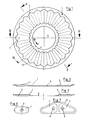
- the filter body according to the invention consists of a plurality of individual filter disks 1 arranged one above the other, which e.g. are connected to one another by welding, a sintering process or by mechanical connecting links. (see Fig. 4).
- the flat outer and inner edges 10 and 11 of the filter disks serve.
- the surface of each filter disc 1 is provided in a wave-like manner with successive ribs 2 and beads 3.
- Each filter disc 1 has a free central interior 4, which is designed as a coaxial bore.
- the inlet channel 6 can open radially, obliquely or - as shown in FIG. 5 - tangentially into an intermediate space 7 between the outer peripheral walls of the filter disks 1 and the inner wall of the filter housing 5.
- the ribs 2 and sikken 3 representing the spacers keep the filter disks 1 lying one above the other at a distance from one another in such a way that input channels 8 and output channels 9 result.
- the filter disks 1 lying one above the other are each placed on top of one another in mirror image.
- the exhaust gases flowing into the intermediate space 7 then flow in the direction of the arrow, owing to the porosity, through the filter walls lying between the inlet and outlet channels 8 and 9, the soot conversion or soot combustion taking place.
- the compression-molded and sintered filter plates will generally be produced from coarse-grained or, even better, chip-like or fibrous metal threads or a mixture thereof.
- Fiber mats or fiber braids formed from finite or endless metal chips or metal fibers can be used for this.
- the free interior 4 forms the exhaust duct.
- ribs 2 and beads 3 are arranged in the radial direction according to the exemplary embodiment according to FIG. 1, in the exemplary embodiment according to FIG. 5 they are curved in the manner of a guide vane, which results in very good flow behavior in connection with the tangential inlet channel .
- the filter disks 1 are designed like a disc in a circular shape.
- FIG. 7 shows an embodiment, wherein two packets of filter disks 1 ', each with an exhaust gas duct 4', are arranged next to one another in a filter housing 5 '.
- the filter disks are designed as an irregular square or kidney-shaped with correspondingly rounded edges.
- the filter walls of the filter disks 1 facing the output channels 9 can be provided with a catalytically active material be layered. If, for example, platinum, vanadium, rhodium or the like is used for this purpose, carbon monoxide, hydrocarbons and nitrogen can also be separated without problems after separation or soot conversion in the filter walls.
- catalyst plates can also be inserted between the abutting ribs 2 and beads 3 of adjacent filter disks, on the surfaces of which the exhaust gases flow on their way to the interior 4.
Landscapes
- Engineering & Computer Science (AREA)
- Chemical & Material Sciences (AREA)
- Combustion & Propulsion (AREA)
- Chemical Kinetics & Catalysis (AREA)
- General Engineering & Computer Science (AREA)
- Mechanical Engineering (AREA)
- Oil, Petroleum & Natural Gas (AREA)
- General Chemical & Material Sciences (AREA)
- Analytical Chemistry (AREA)
- Environmental & Geological Engineering (AREA)
- Biomedical Technology (AREA)
- Health & Medical Sciences (AREA)
- Exhaust Gas After Treatment (AREA)
- Processes For Solid Components From Exhaust (AREA)
- Filtering Of Dispersed Particles In Gases (AREA)
- Filtering Materials (AREA)
- Exhaust Gas Treatment By Means Of Catalyst (AREA)
- Centrifugal Separators (AREA)
- Networks Using Active Elements (AREA)
Applications Claiming Priority (2)
| Application Number | Priority Date | Filing Date | Title |
|---|---|---|---|
| DE4029749 | 1990-09-20 | ||
| DE4029749A DE4029749A1 (de) | 1990-09-20 | 1990-09-20 | Filter |
Publications (2)
| Publication Number | Publication Date |
|---|---|
| EP0482307A1 true EP0482307A1 (fr) | 1992-04-29 |
| EP0482307B1 EP0482307B1 (fr) | 1995-03-22 |
Family
ID=6414589
Family Applications (1)
| Application Number | Title | Priority Date | Filing Date |
|---|---|---|---|
| EP91113548A Expired - Lifetime EP0482307B1 (fr) | 1990-09-20 | 1991-08-13 | Filtre |
Country Status (8)
| Country | Link |
|---|---|
| US (1) | US5215724A (fr) |
| EP (1) | EP0482307B1 (fr) |
| JP (1) | JPH04260411A (fr) |
| KR (1) | KR920006019A (fr) |
| AT (1) | ATE120099T1 (fr) |
| CA (1) | CA2050118A1 (fr) |
| DE (2) | DE4029749A1 (fr) |
| ES (1) | ES2073625T3 (fr) |
Families Citing this family (27)
| Publication number | Priority date | Publication date | Assignee | Title |
|---|---|---|---|---|
| DE4201111C2 (de) * | 1992-01-17 | 1994-03-10 | Daimler Benz Ag | Abgasfilter, insbesondere Rußpartikelfilter |
| DE4234930A1 (de) * | 1992-10-16 | 1994-04-21 | Schwaebische Huettenwerke Gmbh | Filter zum Abscheiden von Verunreinigungen aus Abgasen |
| US5359946A (en) * | 1993-06-08 | 1994-11-01 | Kabushiki Kaisha Daito | Combustion gas purifying method, acid gas remover including calcium compound to remove acid gases, and incinerator equipped with such acid gas remover |
| US5902558A (en) * | 1994-09-26 | 1999-05-11 | Emitec Gesellschaft Fuer Emissionstechnologie Mbh | Diskwise-constructed honeycomb body, in particular catalyst carrier body and apparatus for catalytic conversion of exhaust gases |
| US5494506A (en) * | 1995-01-17 | 1996-02-27 | Ucar Carbon Technology Corporation | Gas filtering device for air bag gas generator |
| US5609837A (en) * | 1995-08-16 | 1997-03-11 | Cerny; David E. | Disinfection apparatus |
| JP3504801B2 (ja) * | 1996-03-26 | 2004-03-08 | 東北リコー株式会社 | マスタ及び孔版印刷装置の版胴及びインキ保持部材 |
| US6309546B1 (en) | 1997-01-10 | 2001-10-30 | Ellipsis Corporation | Micro and ultrafilters with controlled pore sizes and pore size distribution and methods for making |
| GB9801564D0 (en) * | 1998-01-27 | 1998-03-25 | Ici Plc | Catalyst |
| US6168651B1 (en) * | 1998-10-08 | 2001-01-02 | Donaldson Company, Inc. | Filter assembly with shaped adsorbent article; and devices and methods of use |
| JP2003523279A (ja) * | 2000-02-23 | 2003-08-05 | ナムローゼ・フェンノートシャップ・ベーカート・ソシエテ・アノニム | フィルタ素子 |
| WO2001062365A1 (fr) * | 2000-02-23 | 2001-08-30 | N.V. Bekaert S.A. | Element de filtre plisse |
| FR2812221B1 (fr) * | 2000-07-28 | 2003-04-04 | Butachimie | Nouveau dispositif catalytique pour la mise en oeuvre d'une reaction en milieu gazeux a haute temperature |
| DE10117086A1 (de) | 2001-04-06 | 2002-10-17 | Emitec Emissionstechnologie | Verfahren zur Herstellung einer einstückigen, strukturierten Blechfolie mit einem Loch, Blechfolie und Wabenkörper |
| EP1251248A1 (fr) * | 2001-04-18 | 2002-10-23 | OMG AG & Co. KG | Méthode et dispositif pour retirer les particules de suie des gaz d'échappement d'un moteur diesel |
| DE10331347A1 (de) * | 2003-07-11 | 2005-02-03 | Purem Abgassysteme Gmbh & Co. Kg | Filtertasche für einen Partikelfilter |
| DE102004037706A1 (de) * | 2004-08-04 | 2006-03-16 | Purem Abgassysteme Gmbh & Co. Kg | Filterplatte für einen Partikelfilter |
| DE102004038331A1 (de) * | 2004-08-06 | 2006-03-16 | Emitec Gesellschaft Für Emissionstechnologie Mbh | Metallische Fasern, deren Herstellung sowie Einsatzgebiete |
| DE102004054158A1 (de) * | 2004-11-10 | 2006-05-11 | Purem Abgassysteme Gmbh & Co. Kg | Filterplatte für einen Partikelfilter |
| KR100653248B1 (ko) * | 2005-06-23 | 2006-12-01 | 삼성전기주식회사 | 광량 조절 장치 |
| WO2007004941A1 (fr) * | 2005-07-01 | 2007-01-11 | Höganäs Ab | Acier inoxydable pour filtres |
| US8361420B2 (en) | 2007-08-03 | 2013-01-29 | Errcive, Inc. | Porous bodies and methods |
| JP4564520B2 (ja) * | 2007-08-31 | 2010-10-20 | 株式会社東芝 | 半導体記憶装置およびその制御方法 |
| US8277743B1 (en) | 2009-04-08 | 2012-10-02 | Errcive, Inc. | Substrate fabrication |
| US8359829B1 (en) | 2009-06-25 | 2013-01-29 | Ramberg Charles E | Powertrain controls |
| KR101065835B1 (ko) * | 2009-12-28 | 2011-09-19 | 주식회사 리홈 | 기화식 가습기의 임펠러형 디스크 구조체 |
| US9833932B1 (en) | 2010-06-30 | 2017-12-05 | Charles E. Ramberg | Layered structures |
Citations (5)
| Publication number | Priority date | Publication date | Assignee | Title |
|---|---|---|---|---|
| WO1981002686A1 (fr) * | 1980-03-19 | 1981-10-01 | J Bailey | Filtre de substances particulaires contenu dans les gaz d'echappement d'un moteur |
| DE3504694A1 (de) * | 1985-02-12 | 1986-08-14 | Knecht Filterwerke Gmbh, 7000 Stuttgart | Abgasfilter fuer verbrennungsmotoren |
| DE3712872A1 (de) * | 1986-04-18 | 1987-10-22 | Sartorius Gmbh | Filterelement fuer fluide und verfahren zur herstellung eines filterelementes |
| EP0331885A1 (fr) * | 1988-03-10 | 1989-09-13 | Schwäbische Hüttenwerke Gesellschaft mit beschränkter Haftung | Filtre des gaz d'échappements |
| DE3815148A1 (de) * | 1988-05-04 | 1989-11-16 | Eberspaecher J | Anordnung zur lagerung eines von abgas durchstroemten filters in einem metallischen gehaeuse |
Family Cites Families (29)
| Publication number | Priority date | Publication date | Assignee | Title |
|---|---|---|---|---|
| US2267918A (en) * | 1940-03-27 | 1941-12-30 | Gen Motors Corp | Porous article and method of making same |
| US3161478A (en) * | 1959-05-29 | 1964-12-15 | Horst Corp Of America V D | Heat resistant porous structure |
| US3087233A (en) * | 1960-11-16 | 1963-04-30 | Fram Corp | Pervious metal fiber material and method of making the same |
| US3306353A (en) * | 1964-12-23 | 1967-02-28 | Olin Mathieson | Heat exchanger with sintered metal matrix around tubes |
| US3904551A (en) * | 1973-12-19 | 1975-09-09 | Grace W R & Co | Process for preparing an auto exhaust catalytic converter |
| US4064914A (en) * | 1974-05-08 | 1977-12-27 | Union Carbide Corporation | Porous metallic layer and formation |
| US4062807A (en) * | 1975-06-17 | 1977-12-13 | Tokyo Shibaura Electric Co., Ltd. | Nitrogen oxide reducing catalyst |
| US4183896A (en) * | 1976-06-16 | 1980-01-15 | Gordon Donald C | Anti-pollution device for exhaust gases |
| JPS54128842A (en) * | 1978-03-29 | 1979-10-05 | Bridgestone Corp | Thermal collector |
| JPS54152241A (en) * | 1978-04-20 | 1979-11-30 | Mtp Kasei Kk | Solar heat collecting body |
| US4301012A (en) * | 1979-04-25 | 1981-11-17 | Purolator Technologies, Inc. | Welded stainless steel mesh cleanable filter |
| JPS577216A (en) * | 1980-06-16 | 1982-01-14 | Ngk Insulators Ltd | Ceramic honeycomb filter and preparation thereof |
| US4329162A (en) * | 1980-07-03 | 1982-05-11 | Corning Glass Works | Diesel particulate trap |
| AU540009B2 (en) * | 1982-02-16 | 1984-10-25 | Matsushita Electric Industrial Co., Ltd. | Exhaust gas filter |
| DE3232729A1 (de) * | 1982-09-03 | 1984-03-08 | Degussa Ag, 6000 Frankfurt | Verfahren zur herabsetzung der zuendtemperatur von aus dem abgas von dieselmotoren herausgefiltertem dieselruss |
| EP0172642B1 (fr) * | 1984-07-09 | 1989-05-24 | Takeda Chemical Industries, Ltd. | Filtre poudre-air et séparateur pour l'utilisation dans un appareil de remplissage de poudre |
| JPS61287451A (ja) * | 1985-06-13 | 1986-12-17 | Nippon Denso Co Ltd | 排ガス浄化用触媒担体 |
| JPH062204B2 (ja) * | 1985-06-24 | 1994-01-12 | 日本電装株式会社 | セラミツク構造体 |
| DE3527111A1 (de) * | 1985-07-29 | 1987-01-29 | Interatom | Metallischer, gewickelter abgaskatalysatortraegerkoerper mit geometrisch komplizierter form des querschnitts sowie verfahren, vorrichtung und rohling zu seiner herstellung |
| DE3533924A1 (de) * | 1985-09-24 | 1987-06-19 | Schumacher Sche Fab Verwalt | Filterkoerper und verfahren zu dessen herstellung |
| US4725411A (en) * | 1985-11-12 | 1988-02-16 | W. R. Grace & Co. | Device for physical and/or chemical treatment of fluids |
| JPH0657288B2 (ja) * | 1986-03-25 | 1994-08-03 | 旭硝子株式会社 | パテイキユレ−トトラツプ |
| DE3614347A1 (de) * | 1986-04-28 | 1987-10-29 | Didier Werke Ag | Katalysatorbaustein |
| US4687579A (en) * | 1986-05-02 | 1987-08-18 | The United States Of America As Represented By The United States Department Of Energy | Sintered composite medium and filter |
| US4758272A (en) * | 1987-05-27 | 1988-07-19 | Corning Glass Works | Porous metal bodies |
| DE3828348A1 (de) * | 1988-08-20 | 1990-02-22 | Schwaebische Huettenwerke Gmbh | Vorrichtung zur waermeuebertragung |
| DE3828347A1 (de) * | 1988-08-20 | 1990-03-01 | Schwaebische Huettenwerke Gmbh | Abgasfilter fuer heizungs- oder verbrennungsanlagen |
| IT1232749B (it) * | 1989-04-12 | 1992-03-05 | I R T I Istituto Di Ricerca E | Depuratore di gas di scarico ad attivita`catalitica e silenziatore per motori a combustione interna |
| DE3937809A1 (de) * | 1989-11-14 | 1991-05-16 | Schwaebische Huettenwerke Gmbh | Filter zum abscheiden von verunreinigungen |
-
1990
- 1990-09-20 DE DE4029749A patent/DE4029749A1/de not_active Withdrawn
-
1991
- 1991-08-13 DE DE59104991T patent/DE59104991D1/de not_active Expired - Fee Related
- 1991-08-13 ES ES91113548T patent/ES2073625T3/es not_active Expired - Lifetime
- 1991-08-13 AT AT91113548T patent/ATE120099T1/de active
- 1991-08-13 EP EP91113548A patent/EP0482307B1/fr not_active Expired - Lifetime
- 1991-08-28 CA CA002050118A patent/CA2050118A1/fr not_active Abandoned
- 1991-09-04 KR KR1019910015442A patent/KR920006019A/ko not_active Ceased
- 1991-09-05 US US07/755,168 patent/US5215724A/en not_active Expired - Fee Related
- 1991-09-19 JP JP3268490A patent/JPH04260411A/ja active Pending
Patent Citations (5)
| Publication number | Priority date | Publication date | Assignee | Title |
|---|---|---|---|---|
| WO1981002686A1 (fr) * | 1980-03-19 | 1981-10-01 | J Bailey | Filtre de substances particulaires contenu dans les gaz d'echappement d'un moteur |
| DE3504694A1 (de) * | 1985-02-12 | 1986-08-14 | Knecht Filterwerke Gmbh, 7000 Stuttgart | Abgasfilter fuer verbrennungsmotoren |
| DE3712872A1 (de) * | 1986-04-18 | 1987-10-22 | Sartorius Gmbh | Filterelement fuer fluide und verfahren zur herstellung eines filterelementes |
| EP0331885A1 (fr) * | 1988-03-10 | 1989-09-13 | Schwäbische Hüttenwerke Gesellschaft mit beschränkter Haftung | Filtre des gaz d'échappements |
| DE3815148A1 (de) * | 1988-05-04 | 1989-11-16 | Eberspaecher J | Anordnung zur lagerung eines von abgas durchstroemten filters in einem metallischen gehaeuse |
Also Published As
| Publication number | Publication date |
|---|---|
| US5215724A (en) | 1993-06-01 |
| DE4029749A1 (de) | 1992-03-26 |
| DE59104991D1 (de) | 1995-04-27 |
| EP0482307B1 (fr) | 1995-03-22 |
| ATE120099T1 (de) | 1995-04-15 |
| ES2073625T3 (es) | 1995-08-16 |
| CA2050118A1 (fr) | 1992-03-21 |
| JPH04260411A (ja) | 1992-09-16 |
| KR920006019A (ko) | 1992-04-27 |
Similar Documents
| Publication | Publication Date | Title |
|---|---|---|
| EP0482307B1 (fr) | Filtre | |
| EP0428037B1 (fr) | Filtre pour éliminer des impuretées | |
| EP0379032B1 (fr) | Filtre de gaz d'échappement | |
| EP0593004B1 (fr) | Filtre pour éliminer des polluants de gaz d'échappement | |
| DE19704147A1 (de) | Hitzebeständiger und regenerierbarer Filterkörper mit Strömungswegen | |
| DE3818281A1 (de) | Abgasfilter | |
| EP1399241A1 (fr) | Filtre a particules pour gaz d'echappement de moteurs a combustion interne | |
| EP0411421B1 (fr) | Procédé de production d'un filtre et filtre produit ainsi | |
| EP0470365B1 (fr) | Filtre | |
| DE60313151T2 (de) | Behandlung von abgasen aus einem verbrennungsmotor | |
| EP1174599B1 (fr) | Arrangement de filtrage pour un dispositif de purification des gaz d'échappement | |
| DE3910554A1 (de) | Unter verwendung einseitig verschlossener gelochter rohre aufgebautes partikelfilter | |
| EP0577117A2 (fr) | Procédé pour la fabrication d'un catalyseur | |
| DE69708216T2 (de) | Abscheider für diesel- oder benzin-motorabgas und entsprechendes verfahren | |
| EP2299076B1 (fr) | Filtre à particules pour moteur à combustion interne | |
| EP1559882B1 (fr) | Dispositif de purification des gaz d'échappement et procédé de fabrication d'un dispositif de purification des gaz d'échappement | |
| DE4205357C2 (de) | Motorabgasfilter | |
| DE3626729C2 (fr) | ||
| EP1431528B1 (fr) | Dispositif de purification des gaz d'échappement | |
| EP1262640B1 (fr) | Ligne d'échappement d'un moteur à combustion interne, plus particulièrement d'un moteur diesel d'un véhicule utilitaire tel qu'un poids lourd ou un bus, comportant un dispositif de traitement des gaz d'échappement et d'insonorisation intégré | |
| DE19933442A1 (de) | Partikelfilter mit einem Filtermedium und einem Katalysator | |
| DE1907027B2 (de) | Vorrichtung zur Behandlung einer Verbindung in der Gasphase an einem Feststoff | |
| DE10301138A1 (de) | Platzsparende Abgasnachbehandlungseinheit mit ineinanderliegenden Hin- und Rückströmbereichen bei gleichseitigem Gasein- und -austritt | |
| DE10254763A1 (de) | Gekrümmtes Mantelrohr mit Strömungsbeeinflusser, Verfahren zur Herstellung und Verwendung | |
| DE102004026798A1 (de) | Abgaspartikelfilter |
Legal Events
| Date | Code | Title | Description |
|---|---|---|---|
| PUAI | Public reference made under article 153(3) epc to a published international application that has entered the european phase |
Free format text: ORIGINAL CODE: 0009012 |
|
| AK | Designated contracting states |
Kind code of ref document: A1 Designated state(s): AT BE DE ES FR GB IT NL SE |
|
| 17P | Request for examination filed |
Effective date: 19920422 |
|
| 17Q | First examination report despatched |
Effective date: 19930729 |
|
| GRAA | (expected) grant |
Free format text: ORIGINAL CODE: 0009210 |
|
| AK | Designated contracting states |
Kind code of ref document: B1 Designated state(s): AT BE DE ES FR GB IT NL SE |
|
| REF | Corresponds to: |
Ref document number: 120099 Country of ref document: AT Date of ref document: 19950415 Kind code of ref document: T |
|
| REF | Corresponds to: |
Ref document number: 59104991 Country of ref document: DE Date of ref document: 19950427 |
|
| ITF | It: translation for a ep patent filed | ||
| ET | Fr: translation filed | ||
| GBT | Gb: translation of ep patent filed (gb section 77(6)(a)/1977) |
Effective date: 19950616 |
|
| REG | Reference to a national code |
Ref country code: ES Ref legal event code: FG2A Ref document number: 2073625 Country of ref document: ES Kind code of ref document: T3 |
|
| PLBE | No opposition filed within time limit |
Free format text: ORIGINAL CODE: 0009261 |
|
| STAA | Information on the status of an ep patent application or granted ep patent |
Free format text: STATUS: NO OPPOSITION FILED WITHIN TIME LIMIT |
|
| 26N | No opposition filed | ||
| PGFP | Annual fee paid to national office [announced via postgrant information from national office to epo] |
Ref country code: GB Payment date: 19960809 Year of fee payment: 6 |
|
| PGFP | Annual fee paid to national office [announced via postgrant information from national office to epo] |
Ref country code: ES Payment date: 19960813 Year of fee payment: 6 |
|
| PGFP | Annual fee paid to national office [announced via postgrant information from national office to epo] |
Ref country code: AT Payment date: 19960814 Year of fee payment: 6 |
|
| PGFP | Annual fee paid to national office [announced via postgrant information from national office to epo] |
Ref country code: SE Payment date: 19960819 Year of fee payment: 6 |
|
| PGFP | Annual fee paid to national office [announced via postgrant information from national office to epo] |
Ref country code: DE Payment date: 19960822 Year of fee payment: 6 |
|
| PGFP | Annual fee paid to national office [announced via postgrant information from national office to epo] |
Ref country code: FR Payment date: 19960826 Year of fee payment: 6 |
|
| PGFP | Annual fee paid to national office [announced via postgrant information from national office to epo] |
Ref country code: NL Payment date: 19960828 Year of fee payment: 6 |
|
| PGFP | Annual fee paid to national office [announced via postgrant information from national office to epo] |
Ref country code: BE Payment date: 19960904 Year of fee payment: 6 |
|
| PG25 | Lapsed in a contracting state [announced via postgrant information from national office to epo] |
Ref country code: GB Free format text: LAPSE BECAUSE OF NON-PAYMENT OF DUE FEES Effective date: 19970813 Ref country code: AT Free format text: LAPSE BECAUSE OF NON-PAYMENT OF DUE FEES Effective date: 19970813 |
|
| PG25 | Lapsed in a contracting state [announced via postgrant information from national office to epo] |
Ref country code: SE Free format text: LAPSE BECAUSE OF NON-PAYMENT OF DUE FEES Effective date: 19970814 Ref country code: ES Free format text: LAPSE BECAUSE OF EXPIRATION OF PROTECTION Effective date: 19970814 |
|
| PG25 | Lapsed in a contracting state [announced via postgrant information from national office to epo] |
Ref country code: BE Free format text: LAPSE BECAUSE OF NON-PAYMENT OF DUE FEES Effective date: 19970831 |
|
| BERE | Be: lapsed |
Owner name: SCHWABISCHE HUTTENWERKE G.M.B.H. Effective date: 19970831 |
|
| PG25 | Lapsed in a contracting state [announced via postgrant information from national office to epo] |
Ref country code: NL Free format text: LAPSE BECAUSE OF NON-PAYMENT OF DUE FEES Effective date: 19980301 |
|
| GBPC | Gb: european patent ceased through non-payment of renewal fee |
Effective date: 19970813 |
|
| PG25 | Lapsed in a contracting state [announced via postgrant information from national office to epo] |
Ref country code: FR Free format text: LAPSE BECAUSE OF NON-PAYMENT OF DUE FEES Effective date: 19980430 |
|
| PG25 | Lapsed in a contracting state [announced via postgrant information from national office to epo] |
Ref country code: DE Free format text: LAPSE BECAUSE OF NON-PAYMENT OF DUE FEES Effective date: 19980501 |
|
| EUG | Se: european patent has lapsed |
Ref document number: 91113548.1 |
|
| NLV4 | Nl: lapsed or anulled due to non-payment of the annual fee |
Effective date: 19980301 |
|
| REG | Reference to a national code |
Ref country code: FR Ref legal event code: ST |
|
| REG | Reference to a national code |
Ref country code: ES Ref legal event code: FD2A Effective date: 20010201 |
|
| PG25 | Lapsed in a contracting state [announced via postgrant information from national office to epo] |
Ref country code: IT Free format text: LAPSE BECAUSE OF NON-PAYMENT OF DUE FEES;WARNING: LAPSES OF ITALIAN PATENTS WITH EFFECTIVE DATE BEFORE 2007 MAY HAVE OCCURRED AT ANY TIME BEFORE 2007. THE CORRECT EFFECTIVE DATE MAY BE DIFFERENT FROM THE ONE RECORDED. Effective date: 20050813 |