EP0482353A2 - Viseur pour balayer un champ visuel - Google Patents
Viseur pour balayer un champ visuel Download PDFInfo
- Publication number
- EP0482353A2 EP0482353A2 EP91115896A EP91115896A EP0482353A2 EP 0482353 A2 EP0482353 A2 EP 0482353A2 EP 91115896 A EP91115896 A EP 91115896A EP 91115896 A EP91115896 A EP 91115896A EP 0482353 A2 EP0482353 A2 EP 0482353A2
- Authority
- EP
- European Patent Office
- Prior art keywords
- axis
- deflecting mirror
- yaw
- missile
- scanning system
- Prior art date
- Legal status (The legal status is an assumption and is not a legal conclusion. Google has not performed a legal analysis and makes no representation as to the accuracy of the status listed.)
- Granted
Links
Images

Classifications
-
- F—MECHANICAL ENGINEERING; LIGHTING; HEATING; WEAPONS; BLASTING
- F41—WEAPONS
- F41G—WEAPON SIGHTS; AIMING
- F41G7/00—Direction control systems for self-propelled missiles
- F41G7/008—Combinations of different guidance systems
-
- F—MECHANICAL ENGINEERING; LIGHTING; HEATING; WEAPONS; BLASTING
- F41—WEAPONS
- F41G—WEAPON SIGHTS; AIMING
- F41G7/00—Direction control systems for self-propelled missiles
- F41G7/20—Direction control systems for self-propelled missiles based on continuous observation of target position
- F41G7/22—Homing guidance systems
- F41G7/2213—Homing guidance systems maintaining the axis of an orientable seeking head pointed at the target, e.g. target seeking gyro
-
- F—MECHANICAL ENGINEERING; LIGHTING; HEATING; WEAPONS; BLASTING
- F41—WEAPONS
- F41G—WEAPON SIGHTS; AIMING
- F41G7/00—Direction control systems for self-propelled missiles
- F41G7/20—Direction control systems for self-propelled missiles based on continuous observation of target position
- F41G7/22—Homing guidance systems
- F41G7/2246—Active homing systems, i.e. comprising both a transmitter and a receiver
-
- F—MECHANICAL ENGINEERING; LIGHTING; HEATING; WEAPONS; BLASTING
- F41—WEAPONS
- F41G—WEAPON SIGHTS; AIMING
- F41G7/00—Direction control systems for self-propelled missiles
- F41G7/20—Direction control systems for self-propelled missiles based on continuous observation of target position
- F41G7/22—Homing guidance systems
- F41G7/2253—Passive homing systems, i.e. comprising a receiver and do not requiring an active illumination of the target
-
- F—MECHANICAL ENGINEERING; LIGHTING; HEATING; WEAPONS; BLASTING
- F41—WEAPONS
- F41G—WEAPON SIGHTS; AIMING
- F41G7/00—Direction control systems for self-propelled missiles
- F41G7/20—Direction control systems for self-propelled missiles based on continuous observation of target position
- F41G7/22—Homing guidance systems
- F41G7/2273—Homing guidance systems characterised by the type of waves
- F41G7/2286—Homing guidance systems characterised by the type of waves using radio waves
-
- F—MECHANICAL ENGINEERING; LIGHTING; HEATING; WEAPONS; BLASTING
- F41—WEAPONS
- F41G—WEAPON SIGHTS; AIMING
- F41G7/00—Direction control systems for self-propelled missiles
- F41G7/20—Direction control systems for self-propelled missiles based on continuous observation of target position
- F41G7/22—Homing guidance systems
- F41G7/2273—Homing guidance systems characterised by the type of waves
- F41G7/2293—Homing guidance systems characterised by the type of waves using electromagnetic waves other than radio waves
-
- G—PHYSICS
- G02—OPTICS
- G02B—OPTICAL ELEMENTS, SYSTEMS OR APPARATUS
- G02B26/00—Optical devices or arrangements for the control of light using movable or deformable optical elements
- G02B26/08—Optical devices or arrangements for the control of light using movable or deformable optical elements for controlling the direction of light
- G02B26/0816—Optical devices or arrangements for the control of light using movable or deformable optical elements for controlling the direction of light by means of one or more reflecting elements
-
- G—PHYSICS
- G02—OPTICS
- G02B—OPTICAL ELEMENTS, SYSTEMS OR APPARATUS
- G02B26/00—Optical devices or arrangements for the control of light using movable or deformable optical elements
- G02B26/08—Optical devices or arrangements for the control of light using movable or deformable optical elements for controlling the direction of light
- G02B26/10—Scanning systems
-
- G—PHYSICS
- G02—OPTICS
- G02B—OPTICAL ELEMENTS, SYSTEMS OR APPARATUS
- G02B7/00—Mountings, adjusting means, or light-tight connections, for optical elements
- G02B7/18—Mountings, adjusting means, or light-tight connections, for optical elements for prisms; for mirrors
- G02B7/182—Mountings, adjusting means, or light-tight connections, for optical elements for prisms; for mirrors for mirrors
- G02B7/1821—Mountings, adjusting means, or light-tight connections, for optical elements for prisms; for mirrors for mirrors for rotating or oscillating mirrors
Definitions
- the invention relates to a viewfinder in which a visual field can be scanned through a limited light passage opening by an optical scanning system with a fixed detector and at least one oscillating mirror.
- the invention relates to the fact that the visual scanning system in a missile can be used to scan a field of view lying in the direction of flight of the missile through a window provided laterally from the tip of the missile and inclined to the longitudinal axis of the missile.
- a missile's seeker should track a target approximately in the direction of flight.
- a radar finder should also be provided.
- the imaging optics of the viewfinder and the detector sit on a frame system that allows movement about a pitch and a yaw axis.
- This frame system can be moved on a slide in the longitudinal axis of the missile.
- the invention has for its object to provide a viewfinder of the type mentioned so that it allows a large squint angle around the yaw axis without a corresponding enlargement of the light passage opening.
- this object is achieved in that the oscillating mirror by a drive mechanism can be driven in a coordinated manner about two axes such that the optical axis of the scanning system which carries out a scanning movement always runs essentially through a fixed point located in the light passage opening.
- Embodiments of the invention are the subject of the dependent claims.
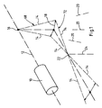
- 10 denotes an infrared-responsive detector.
- the detector 10 lies on a roll axis 12 which runs parallel to the longitudinal axis of the missile.
- a scanning system (not shown in FIG. 1) has an optical axis 14.
- the optical axis 14 runs along the roll axis 12, is deflected at a point 16 lying on the roll axis 12 and carries out an oscillating movement about the roll axis 12. This is indicated in Figure 1 by the double arrow 18.
- the optical axis 14 of the scanning system carries out an oscillating movement about a yaw axis (oscillating about the roll axis).
- the yaw axis is designated 20 and shown in FIG.
- the oscillating movement of the optical axis 14 about the respective yaw axis 20 is coordinated with the oscillating movement of the optical axis 14 about the roll axis 12 such that the optical axis 14 always passes through a fixed point 22 and oscillates about a "virtual yaw axis" 24. This point 22 can then be placed on the center of the side window of the missile.
- Missile 26 is a high speed missile.
- the missile 26 has an asymmetrical front part.
- a viewfinder 30 working with radar.
- Such viewfinders are known per se. The structure of the viewfinder 30 is therefore not described in detail here.
- a flat window 32 adjoins the tip 28.
- the window 32 is transparent to infrared.
- An infrared finder 34 is located behind the tip 28 and behind the window 32.
- the viewfinder 34 contains the infrared-responsive detector 10 and an optical scanning system with a vibrating optical axis. The viewfinder 34 observes a field of view lying in the direction of flight of the missile through the window 32.
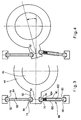
- the viewfinder 34 contains a rolling frame 36.
- the rolling frame 36 can be driven by a torque generator 38 about the rolling axis 12 parallel to the longitudinal axis of the missile.
- the movement of the torque generator 38 about the roll axis 12 is monitored by an angle tap 40.
- the detector 10 is also structurally fixed in FIG. 2 on the structurally fixed roll axis.
- the torque generator 38 is controlled so that the rolling frame 36 executes a defined oscillating movement about the rolling axis 12.
- a yaw frame 44 is rotatably mounted about a real yaw axis 20 (FIG. 1) in the rolling frame 36.
- the rolling frame 36 contains an imaging lens 46 and a flat deflecting mirror 48.
- the imaging lens 46 is arranged coaxially with the yaw axis 20.
- the deflection mirror 48 sits in the beam path between the imaging lens 46 and the detector 10.
- the deflection mirror 48 is inclined against the yaw axis 20.
- the yaw frame 44 is held pivotable by means of an arm 50 about a structurally fixed point 52 lying outside the yaw axis 20. The result of this is that when the rolling frame 34 swings about the rolling axis 12, the yaw frame 44 carries out a swinging movement about the yaw axis 20.
- the beam path of the scanning system continues through a flat deflecting mirror 54.
- the deflecting mirror 54 is seated on the yaw frame 44 and the deflecting mirror 54 is mounted on the yaw frame so as to be able to oscillate about a pitch axis 56.
- the deflection mirror 54 can be driven by a torque generator 58 via a crank mechanism 60 and carries out an oscillating movement about the pitch axis 56.
- the movement of the deflecting mirror 54 about the pitch axis 56 can be tapped off by an angle tap 62.
- the beam path of the imaging light bundle 64 with the optical axis 14 runs through the window 32, over the deflection mirror 54, through the imaging lens 46 and over the deflection mirror 48 and is collected on the detector 10.
- the optical axis 14 executes a two-dimensional scanning movement, so that the visual field is scanned.
- the deflecting mirror 54 directs the optical axis 14 essentially in the direction of flight of the missile 26 through the window 32.
- the respective direction of the optical axis 14 and the imaging light bundle 64 can be tapped off by the angle taps 40 and 62.
- FIG. 2 shows the rolling frame 36, the deflecting mirror 48 (with the yaw frame 44) and the deflecting mirror 54 in their central position.
- the arrangement is symmetrical to the paper plane of Fig.2.
- the imaging lens 46 and the deflecting mirror 48 are moved forward with the yaw frame 44 out of the paper plane of FIG.
- the diverging beam path 66 emanating from the fixed detector 10 then also extends forwards out of the paper plane from FIG. 2 to the deflecting mirror 48 and the imaging lens 46. This corresponds approximately to the course of the optical axis 14 shown at 68 in FIG.
- the yaw frame 44 Since the yaw frame 44 is pivotally mounted about the structurally fixed point 52 lying outside the yaw axis 20, during this "forward movement" of the yaw frame 44 the yaw frame is simultaneously rotated counter-clockwise around the yaw axis 20 when viewed from above in FIG. 2. As a result, the deflecting mirror 48 is correspondingly rotated about the yaw axis 20. The bundle section reflected from it 70 is pivoted to the rear in FIG. 2. This corresponds to the course of the optical axis 14 shown at 72 in FIG. 1. This counteracts the forward movement of the yaw frame 44 during the oscillating movement of the rolling frame 34.
- a corresponding, reversed sign occurs when the yaw frame 44 is moved backwards in FIG.
- the optical axis 14 always passes through the fixed point 22 on the window 32 and swings about a "virtual yaw axis" 24 when the deflecting mirror 54 is initially assumed to be stationary in the central position.
- the window 32 then essentially only needs to be wide enough to let the cross section of the imaging light beam 64 pass through.
- the light bundle 64 is not covered by the boundaries of the window during the oscillating movement of the imaging light bundle 64.
- the beam path for larger swiveling angles of the deflecting mirror shifts laterally out of the center of the window 32.
- the arrangement is optimized so that the movement of the imaging light bundle in the region of the window 32 is as small as possible.
- 3 and 4 show a constructive solution as to how point 52 can be determined.
- Hemispherical depressions 74, 76 are provided on arm 50 on opposite sides. Hemispherical depressions 78 and 80 are provided on the structure of the missile 26 at a distance from the depressions 74 and 76.
- Thrust pieces 82 and 84 are each formed by a rod 88 or 90 with joint balls 92, 94 or 96.98. These thrust pieces 84 and 86 are each supported with a joint ball 92 and 98 in one of the structurally fixed, hemispherical recesses 78 and 80 and engage with the other joint balls 94 and 96 in the hemispherical recesses 74 and 76 of the arm 50.
- the rod 90 consists of two telescoping parts 100 and 102 which are pressed apart by a coil spring 104.
- the yaw frame 44 is held pivotable in this way about an essentially structurally fixed point 52, but the holding means permit a certain kinematically required compensating movement.
Landscapes
- Engineering & Computer Science (AREA)
- Physics & Mathematics (AREA)
- Chemical & Material Sciences (AREA)
- Combustion & Propulsion (AREA)
- General Engineering & Computer Science (AREA)
- General Physics & Mathematics (AREA)
- Optics & Photonics (AREA)
- Electromagnetism (AREA)
- Aiming, Guidance, Guns With A Light Source, Armor, Camouflage, And Targets (AREA)
- Optical Radar Systems And Details Thereof (AREA)
Applications Claiming Priority (2)
| Application Number | Priority Date | Filing Date | Title |
|---|---|---|---|
| DE4033948A DE4033948A1 (de) | 1990-10-25 | 1990-10-25 | Sucher zur abtastung eines gesichtsfeldes |
| DE4033948 | 1990-10-25 |
Publications (3)
| Publication Number | Publication Date |
|---|---|
| EP0482353A2 true EP0482353A2 (fr) | 1992-04-29 |
| EP0482353A3 EP0482353A3 (en) | 1993-03-03 |
| EP0482353B1 EP0482353B1 (fr) | 1996-11-20 |
Family
ID=6417035
Family Applications (1)
| Application Number | Title | Priority Date | Filing Date |
|---|---|---|---|
| EP91115896A Expired - Lifetime EP0482353B1 (fr) | 1990-10-25 | 1991-09-19 | Viseur pour balayer un champ visuel |
Country Status (2)
| Country | Link |
|---|---|
| EP (1) | EP0482353B1 (fr) |
| DE (2) | DE4033948A1 (fr) |
Cited By (4)
| Publication number | Priority date | Publication date | Assignee | Title |
|---|---|---|---|---|
| EP0628781A1 (fr) * | 1993-05-12 | 1994-12-14 | Bodenseewerk Gerätetechnik GmbH | Autodirecteur pour missile |
| FR2716966A1 (fr) * | 1994-03-01 | 1995-09-08 | Thomson Csf | Système de défense anti-aérienne à très courte portée, de type missile sol-air. |
| DE102007003699B3 (de) * | 2007-01-25 | 2008-10-02 | Lfk-Lenkflugkörpersysteme Gmbh | Optisches Fenster in einem Infrarot-Zielsuchkopf |
| EP2957854A1 (fr) * | 2014-06-17 | 2015-12-23 | MBDA Italia | Chercheur bi-mode |
Family Cites Families (6)
| Publication number | Priority date | Publication date | Assignee | Title |
|---|---|---|---|---|
| DE1803608B2 (de) * | 1968-10-17 | 1971-12-02 | Opto elektronisches abtastgeraet | |
| GB2103824B (en) * | 1981-08-20 | 1984-09-26 | Marconi Co Ltd | Scanning mirror systems |
| DE3301274A1 (de) * | 1983-01-17 | 1984-07-19 | Bodenseewerk Gerätetechnik GmbH, 7770 Überlingen | Antrieb fuer einen um eine schwingachse beweglichen schwingspiegel bei optischen geraeten |
| US4867548A (en) * | 1986-07-25 | 1989-09-19 | Hughes Aircraft Company | Linkage articulated pointing mirror |
| US4717822A (en) * | 1986-08-04 | 1988-01-05 | Hughes Aircraft Company | Rosette scanning surveillance sensor |
| DE3807725A1 (de) * | 1988-03-09 | 1989-09-21 | Bodenseewerk Geraetetech | Endphasengelenktes geschoss |
-
1990
- 1990-10-25 DE DE4033948A patent/DE4033948A1/de not_active Withdrawn
-
1991
- 1991-09-19 EP EP91115896A patent/EP0482353B1/fr not_active Expired - Lifetime
- 1991-09-19 DE DE59108363T patent/DE59108363D1/de not_active Expired - Fee Related
Cited By (4)
| Publication number | Priority date | Publication date | Assignee | Title |
|---|---|---|---|---|
| EP0628781A1 (fr) * | 1993-05-12 | 1994-12-14 | Bodenseewerk Gerätetechnik GmbH | Autodirecteur pour missile |
| FR2716966A1 (fr) * | 1994-03-01 | 1995-09-08 | Thomson Csf | Système de défense anti-aérienne à très courte portée, de type missile sol-air. |
| DE102007003699B3 (de) * | 2007-01-25 | 2008-10-02 | Lfk-Lenkflugkörpersysteme Gmbh | Optisches Fenster in einem Infrarot-Zielsuchkopf |
| EP2957854A1 (fr) * | 2014-06-17 | 2015-12-23 | MBDA Italia | Chercheur bi-mode |
Also Published As
| Publication number | Publication date |
|---|---|
| DE59108363D1 (de) | 1997-01-02 |
| DE4033948A1 (de) | 1992-04-30 |
| EP0482353B1 (fr) | 1996-11-20 |
| EP0482353A3 (en) | 1993-03-03 |
Similar Documents
| Publication | Publication Date | Title |
|---|---|---|
| DE4135260C1 (fr) | ||
| DE69109958T2 (de) | Optisches Tag-Nachtsichtgerät. | |
| EP2533003B1 (fr) | Dispositif optique destiné au guidage du rayonnement d'une scène sur un détecteur | |
| EP1308748B1 (fr) | Capteur optique avec un trajet optique et un laser transmettant un faisceau parallèle à l'axe optique du trajet optique | |
| DE69205852T2 (de) | Wärmebildsystem. | |
| DE19728035A1 (de) | Beobachtungsvorrichtung mit Schrägbeleuchtung | |
| EP0055209B1 (fr) | Dispositif pour faire tourner des faisceaux lumineux | |
| DE69805163T2 (de) | Optisches system | |
| DE3919265A1 (de) | Opto-elektronische ausblickbaugruppe | |
| DE3829708A1 (de) | Umschaltbarer winkelspiegel fuer periskope | |
| EP0482353B1 (fr) | Viseur pour balayer un champ visuel | |
| EP1026534A1 (fr) | Système de télescope orientable | |
| EP2131229A2 (fr) | Dispositif doté d'un système de détermination optique | |
| EP0385079B1 (fr) | Système de visualisation pour véhicules en chaîne | |
| DE2129778A1 (de) | Verbesserungen an Beobachtungsgeraeten | |
| DE3044114C2 (de) | Optisch-mechanischer Abtaster | |
| EP0140836A2 (fr) | Appareil optique pour engendrer une image visuelle stéréoscopique | |
| DE2623955B1 (de) | Periskopisches winkelspiegelsystem mit umschaltbarer blickrichtung | |
| EP0533036B1 (fr) | Tête chercheuse | |
| DE3609774C2 (fr) | ||
| DE1772827B2 (fr) | ||
| EP4125165B1 (fr) | Dispositif de mise au point doté d'un plan image s'étendant parallèle ou continu par rapport à un plan cible | |
| DE2951592C2 (de) | Verfahren und Vorricntung zum Überwachen eines großen Raumwinkels | |
| DE2841776C2 (de) | Einrichtung zur optisch-mechanischen Abstastung | |
| DE2347931C3 (de) | Projektor zum Projizieren eines kontinuierlich bewegbaren Filmes auf eine Bildebene |
Legal Events
| Date | Code | Title | Description |
|---|---|---|---|
| PUAI | Public reference made under article 153(3) epc to a published international application that has entered the european phase |
Free format text: ORIGINAL CODE: 0009012 |
|
| AK | Designated contracting states |
Kind code of ref document: A2 Designated state(s): DE FR GB |
|
| PUAL | Search report despatched |
Free format text: ORIGINAL CODE: 0009013 |
|
| AK | Designated contracting states |
Kind code of ref document: A3 Designated state(s): DE FR GB |
|
| 17P | Request for examination filed |
Effective date: 19930730 |
|
| 17Q | First examination report despatched |
Effective date: 19941230 |
|
| GRAG | Despatch of communication of intention to grant |
Free format text: ORIGINAL CODE: EPIDOS AGRA |
|
| GRAH | Despatch of communication of intention to grant a patent |
Free format text: ORIGINAL CODE: EPIDOS IGRA |
|
| GRAH | Despatch of communication of intention to grant a patent |
Free format text: ORIGINAL CODE: EPIDOS IGRA |
|
| GRAA | (expected) grant |
Free format text: ORIGINAL CODE: 0009210 |
|
| AK | Designated contracting states |
Kind code of ref document: B1 Designated state(s): DE FR GB |
|
| ET | Fr: translation filed | ||
| REF | Corresponds to: |
Ref document number: 59108363 Country of ref document: DE Date of ref document: 19970102 |
|
| GBT | Gb: translation of ep patent filed (gb section 77(6)(a)/1977) |
Effective date: 19970211 |
|
| PGFP | Annual fee paid to national office [announced via postgrant information from national office to epo] |
Ref country code: GB Payment date: 19970905 Year of fee payment: 7 |
|
| PGFP | Annual fee paid to national office [announced via postgrant information from national office to epo] |
Ref country code: FR Payment date: 19970915 Year of fee payment: 7 |
|
| PLBE | No opposition filed within time limit |
Free format text: ORIGINAL CODE: 0009261 |
|
| STAA | Information on the status of an ep patent application or granted ep patent |
Free format text: STATUS: NO OPPOSITION FILED WITHIN TIME LIMIT |
|
| 26N | No opposition filed | ||
| PG25 | Lapsed in a contracting state [announced via postgrant information from national office to epo] |
Ref country code: GB Free format text: LAPSE BECAUSE OF NON-PAYMENT OF DUE FEES Effective date: 19980919 |
|
| GBPC | Gb: european patent ceased through non-payment of renewal fee |
Effective date: 19980919 |
|
| PG25 | Lapsed in a contracting state [announced via postgrant information from national office to epo] |
Ref country code: FR Free format text: LAPSE BECAUSE OF NON-PAYMENT OF DUE FEES Effective date: 19990531 |
|
| REG | Reference to a national code |
Ref country code: FR Ref legal event code: ST |
|
| PGFP | Annual fee paid to national office [announced via postgrant information from national office to epo] |
Ref country code: DE Payment date: 19991124 Year of fee payment: 9 |
|
| PG25 | Lapsed in a contracting state [announced via postgrant information from national office to epo] |
Ref country code: DE Free format text: LAPSE BECAUSE OF NON-PAYMENT OF DUE FEES Effective date: 20010601 |