EP0482354B1 - Aktenordner oder Schreibplatte - Google Patents
Aktenordner oder Schreibplatte Download PDFInfo
- Publication number
- EP0482354B1 EP0482354B1 EP91115920A EP91115920A EP0482354B1 EP 0482354 B1 EP0482354 B1 EP 0482354B1 EP 91115920 A EP91115920 A EP 91115920A EP 91115920 A EP91115920 A EP 91115920A EP 0482354 B1 EP0482354 B1 EP 0482354B1
- Authority
- EP
- European Patent Office
- Prior art keywords
- guide
- mounting plate
- ring binder
- writing board
- base plate
- Prior art date
- Legal status (The legal status is an assumption and is not a legal conclusion. Google has not performed a legal analysis and makes no representation as to the accuracy of the status listed.)
- Expired - Lifetime
Links
Images






Classifications
-
- B—PERFORMING OPERATIONS; TRANSPORTING
- B42—BOOKBINDING; ALBUMS; FILES; SPECIAL PRINTED MATTER
- B42F—SHEETS TEMPORARILY ATTACHED TOGETHER; FILING APPLIANCES; FILE CARDS; INDEXING
- B42F9/00—Filing appliances with devices clamping file edges; Covers with clamping backs
-
- B—PERFORMING OPERATIONS; TRANSPORTING
- B42—BOOKBINDING; ALBUMS; FILES; SPECIAL PRINTED MATTER
- B42F—SHEETS TEMPORARILY ATTACHED TOGETHER; FILING APPLIANCES; FILE CARDS; INDEXING
- B42F13/00—Filing appliances with means for engaging perforations or slots
- B42F13/0006—Covers for loose-leaf binders
- B42F13/0066—Covers for loose-leaf binders with means for attaching the filing appliance to the cover
- B42F13/0073—Covers for loose-leaf binders with means for attaching the filing appliance to the cover removable
-
- B—PERFORMING OPERATIONS; TRANSPORTING
- B42—BOOKBINDING; ALBUMS; FILES; SPECIAL PRINTED MATTER
- B42F—SHEETS TEMPORARILY ATTACHED TOGETHER; FILING APPLIANCES; FILE CARDS; INDEXING
- B42F13/00—Filing appliances with means for engaging perforations or slots
- B42F13/16—Filing appliances with means for engaging perforations or slots with claws or rings
Definitions
- the invention relates to a file folder or a writing board, the file folder being provided with a back part and with cover parts as wall parts, which and the back part are integrally connected to one another via articulated grooves and with at least one line-up device arranged on the inner wall surface of a wall part and secured to a base plate
- Two- or multi-ring rocker arm or tear mechanism for loose, perforated sheets which is releasably held with its base plate by means of a holder arranged on the file folder wall part on the file folder wall part, into which the base plate engages, and wherein the writing plate is provided with a clamping mechanism having a base plate is, wherein the holder for the base plate is designed as a mounting plate, which and the base plate in the assembled state are arranged on different sides of a cover part or the back part of the file folder or on the upper edge of the writing plate d.
- the line-up device In conventional file folders, the line-up device is firmly connected to the actual folder with its base plate. The problem arises that they take up a lot of space even when empty. Although it is possible to insert two folders into each other, this measure also reduces the space requirement to only about half the space that they occupy. This is a problem in warehousing, transportation and sales.
- a file folder with a ring mechanism attached to it is from US-A-4,765,768 taken into account in the preamble known.
- the ring mechanism consists of two plate-shaped blanks, of which one blank has the rings of the ring mechanism as a support plate, while the other blank forms a counter-holder, which rests on the outside of the back part of the file folder and which carries a number of snap-in pins with hook-shaped heads, which are passed through hole-like openings in the rear wall of the file folder and engage in openings in the carrier plate carrying the rings of the ring mechanism.
- a large number of locking pins are provided in order to create a clamping connection to the support plate with the rings of the ring mechanism.
- a loosening of the clamp connection is not provided at all due to the large number of snap-in pins used and is very troublesome, since the hook-shaped snap-in pins have to be pressed out individually from the openings in the support plate with the rings, so that damage to the snap-in pins cannot be avoided.
- a filing device for file folders is known, which is held by means of a mounting plate on the inner wall surface of the rear cover part.
- the mounting plate for the line-up device is placed on the inner wall surface of the rear cover part and permanently connected to it.
- the line-up device is held by means of its base plate in guides formed on the mounting plate such that the line-up device with its base plate can be removed from the mounting plate is possible.
- the mounting plate emerges from the plane formed by the inner wall surface of the cover part, so that damage can be caused to the protruding mounting plate by the protruding mounting plate in the unfolded state for the transport of stacked files in the unfolded state during transport, as the mounting plate on the outer wall surface of the respective file folder above.
- the terminal strip is very bulky and does not allow space-saving stacking.
- a writing board with a clamping strip which consists of two clamping legs under the action of a spring, which are connected in a hinge-like manner and are provided with gripping teeth on their mutually facing leg edges, so that, for example, single sheets between the by means of Spring pressure pressed together thigh edges are kept.
- the clamping strip is fastened to the writing surface by means of a rivet connection, the clamping leg on the writing surface being arranged on the writing surface or on the underside of the writing surface, the parts which are formed on this clamping leg and form the hinge being passed through slot-shaped openings in the writing surface, around which to connect the hinge parts formed on the other clamping leg to the hinge parts passed through the openings by means of a pivot axis.
- no guide and holding rails are used to fasten the terminal block to the writing plate, which are guided through slot-shaped openings in the writing plate and into which a base plate with one of the two clamping legs can be inserted.
- the invention has for its object to provide a file folder or a writing plate of the type mentioned, which can be stacked with little space without damaging the individual file folders or writing plates and is easy to produce with a line-up device or with a clamping mechanism, even with one large load on the line-up device or clamping device, the line-up device cannot be torn out of the file cover and the line-up mechanism or the clamping mechanism can be loosened without damage.
- a file folder or writing plate designed in this way consists of three parts, namely the actual folder, the line-up device with the base plate and the mounting plate. All three parts are easy to transport and do not take up much space.
- the folder with the removed line-up device and mounting plate can be stacked on top of one another in the unfolded state of its wall parts; Packing several file folders for dispatch is also effortless and can be carried out without taking up much space.
- the terminal strip is also detachably arranged on the writing plate blank.
- the base plate can be attached to the mounting plate in any suitable manner; clamp closures or snap closures are conceivable.
- the guide and holding rails formed on the mounting plate provide a simple embodiment which is, however, distinguished by a high degree of stability, in particular when guide and holding rails for receiving the base plate are provided on three sides of the mounting plate are provided. Two of these guide and holding rails are provided parallel to one another on the mounting plate, which are used in particular to guide the base plate during insertion, whereas a third rail, which is perpendicular to the other two guide and holding rails, serves as a stop for the final positioning of the base plate.
- This third guide and holding rail is designed so that an additional mounting of the base plate takes place.
- a clamping device is provided for locking the base plate inserted into the guide and holding rails of the mounting plate, which prevents the base plate from detaching from the mounting plate. In this way, it is permitted to prevent the base plate from accidentally detaching from the mounting plate.
- This clamping and locking device can be designed so that it is no longer possible to disassemble the folder without destroying it.
- the embodiment according to claim 9 is particularly advantageous here, according to which eyelets made of plastic or metallic materials are used in the openings for the guide and holding rails in the rear cover part of the file folder and are used to achieve a specified dimensional accuracy in relation to the thickness of the cover part .
- eyelets made of plastic or metallic materials are used in the openings for the guide and holding rails in the rear cover part of the file folder and are used to achieve a specified dimensional accuracy in relation to the thickness of the cover part .
- the lid parts and also the back part of folders are provided with a covering made of a plastic film or a structured material, such as, for example, with a skin grain, whereby the thickness of the lid parts can vary.
- the openings in the wall part of the file folder are provided with eyelets, which rest on the circumferential edges that delimit the openings and ensure a constant wall thickness of the wall parts of the folder, so that always an effortless insertion of the base plate with the line-up device into the guide and holding rails of the mounting plate attached to the cover part of the folder is ensured.
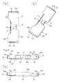
- 10 denotes a file folder which consists of a front cover part 11, a rear cover part 12 and a back part 13 connecting the two cover parts to one another.
- the back and cover parts are integrally connected to one another via joint or fold grooves 14, 14a.
- a reinforced grip hole 15 is formed in the back part 11.
- a line-up device 20 Arranged on the inner wall surface 12b of the rear cover part 12 is a line-up device 20 which is fastened to the cover part 12 by means of a holder which is described in more detail below.
- This line-up device 20 is designed as a lever mechanism with lockable brackets 21, 22 that hold the document to be filed and provided with perforations, of which each bracket 21, 22 has a two-part shape with fixed bracket legs 21a, 22a and bracket legs 21b, 22b that can be pivoted by means of the tilting mechanism.
- the fixed stirrup legs 21a, 22a and the pivotable stirrup legs 21b, 22b are arranged together with the tilt mechanism on a base plate 25.
- the line-up device 20 is designed as a two- or multi-ring rocker arm mechanism or as a two- or multi-ring tearing mechanism, with multi-ring mechanisms, which consist of 18 rings, for example, can be used.
- the line-up device 20 is fastened to the inner wall surface 12b of the rear cover part 12 or to the inner wall surface of the back part 13.
- Back and lid parts 11, 12, 13 of folder 10 are e.g. made of cardboard or cardboard, the cardboard blank is covered with cloud marble paper on the outside and paper on the inside.
- the cardboard blank laminated on the outside with cloud marble paper and on the inside with paper can also be designed such that both laminations are additionally coated with a plastic, in particular extrusion-coated.
- the cardboard blank can or the like on the outside and / or on the inside with a plastic film. be covered or concealed.
- the coating material can be structured; e.g. have a skin scar.
- the two cover parts 11, 12 and the back part 13 can be provided with edge protection strips, not shown in the drawing, which are made of plastic or metallic materials.
- two slots 11a, 11b are provided for expanding the capacity, into which the brackets 21, 22 of the lever mechanism engage.
- a ratchet cam 11a ', 11b' Above the lower edges of the two slots 11a, 11b there is a ratchet cam 11a ', 11b', the surface facing the slot of which is designed as a rising sliding surface in order to achieve a detachable connection between the lever mechanism and the front cover part 11, thereby preventing is that the two cover parts 11, 12 automatically set up laterally (Fig. 1).
- the base plate 25 of the aligning device 20 is fastened by means of the holder, which is designed as a mounting plate 30.
- the mounting plate 30 consists of sheet steel and has an approximately rectangular plate cut 31 with the long sides 31a, 31b and the narrow sides 31c, 31d.
- the plate blank 31 of the mounting plate 30 has guide and holding rails 32, 33, which consist of sections bent at a right angle from the plane of the plate in the edge region with upper edge sections angled slightly inwards.
- the guide and holding rails 32, 33 are produced by appropriate material deformation.
- Each guide and holding rail 32, 33 is formed by a leg 32a, 33a, which is perpendicular to the panel cut 31 of the mounting plate 30 and merges into an angled, upper edge portion 32b, 33b, so that guide openings 32c, 33c are obtained (FIGS. 6 and 7).
- the two guide and holding rails 32, 33 are arranged at a distance from one another which is dimensioned such that between the two vertical legs 32a, 33a the base plate 25 can be inserted, which is held between the vertical legs 32a, 33a and which is angled from the upper edge sections 32b, 33b is secured against lifting (Fig. 8).
- a further guide and holding rail 34 is provided on the long side 31a of the plate blank 31 of the mounting plate 30, which is designed in accordance with the guide and holding rails 32, 33 and also consists of a leg 34a perpendicular to the panel blank 31 with an upper, angled edge portion 34b.
- the three guide and holding rails 32, 33, 34 are at right angles to one another and form approximately a U.
- leg 34a with the upper, angled edge portion 34b takes place after the base plate 25 has been inserted into the parallel guide and holding rails 32, 33 on the base plate; this guide and holding rail 34 limits the further insertion of the base plate 25 and contributes to a firm fit of the base plate 25 on the mounting plate 30.
- the mounting plate 30 has a clamping and locking device 40, which consists of a resilient-elastic tongue 41 formed from the plate blank 31, which, as shown in FIG. 5, faces the guide and holding rail 34. After the base plate 25 has been inserted into the guide and holding rails 32, 33, the base plate is secured on the mounting plate against being pulled off by means of this clamping tongue 41. If the mounting plate 30 consists of a steel sheet, then the resilient-elastic property of the steel sheet is used for the function of the clamping tongue 41.
- the length of the guide and holding rails 32, 33 of the mounting plate 30 corresponds approximately to the length of the narrow sides of the base plate 25, and the guide and holding rails 32, 33 can also have a shorter length.
- the length of the guide and holding rail 34 can be chosen as desired. A sufficient hold of the base plate 25 on the mounting plate 30 is already achieved by the two guide and holding rails 32, 33.
- the cover part 12 has a number of slot-shaped openings 16, 17, 18 corresponding to the number of guide and holding rails 32, 33, 34 on (Fig. 1 and 3). Another opening 19 is provided in the cover part 12 for passing the clamping tongue 41 through. These openings 16, 17, 18, 19 in the cover part 12 are dimensioned such that the guide and holding rails 32, 33, 34 and the clamping tongue 41 reach through and through the openings when the mounting plate 30 is placed on the outer wall surface 12a of the cover part 12 of the inner wall surface 12b of the cover part 12 protrude so far that the guiding and holding function for the base plate 25 remains.
- the mounting plate 30 bears against the outer wall surface 12a of the cover part 12, while the guide and holding rails 32, 33, 34 and the clamping tongue 41 protrude from the inner wall surface 12b of the cover part 12 (FIG. 8).
- FIGS. 4 to 7 consists of thin sheet steel and after assembly together with the base plate 25 of the aligning device 20 only slightly protrudes from the outer wall surface 12a of the cover part 12, according to a further embodiment according to FIGS Mounting plate 130 made of plastics, wherein the guide and holding rails 32, 33, 34 provided on this mounting plate 130 and the clamping device 40 are also formed during the production of the mounting plate, but there is also the possibility of guiding and holding rails and a clamping device 40 another material and to connect to the panel blank of the mounting plate 130 by means of permanent connections, such as screw or rivet connections.
- the file folder 10 partially shown in FIG. 9 also consists of the two cover parts 11, 12 and the back part 13.
- the mounting plate 130 is arranged on the outer wall surface 12a of the cover part 12, with the guide and. Through the slot-shaped openings 16, 17, 18 Projecting support rails 32,33,34 and come to rest with their upper engagement areas on the inside of the cover part 12.
- the base plate 25 of the alignment device 20, guided by the guide and holding rails 32, 33, is inserted into the mounting plate 30 in the direction of the arrow X, the guide and holding rail 34 defining the end position of the base plate 25.
- the guide and holding rail 34 defining the end position of the base plate 25.
- the guide and holding rails 32, 33 run parallel to the longitudinal direction of the back part 13 of the folder 10; the direction of insertion for the base plate 25 into the guide and holding rails 32, 33 of the mounting plate 30 then also takes place parallel to the longitudinal direction of the back part 13 of the folder 10.
- FIGS. 10 and 11 essentially corresponds to the embodiment shown in FIG.
- a clamping and locking device 40 is also provided here, which is designed as a bent tab 41 'in the mounting plate 25.
- This locking tab 41 ′ prevents inadvertent detachment of the base plate 25 of the line-up device 20 from the mounting plate 30.
- the base plate 25 is inserted into the guide and holding rails of the mounting plate 130 in the direction of the arrow X1 parallel to the narrow sides of the base plate 25, ie transversely to the longitudinal direction of the narrow back part 13 of the Folder 10 (Fig.12).
- the guide and holding rails 32, 33, which run parallel to the narrow sides of the base plate 25, guide the base plate 25 during insertion, while the guide and holding rail 34, which runs parallel to the long sides of the base plate 25, defines the end position of the base plate 25 of the aligning device 20.
- FIGS. 14 to 17 largely correspond to the embodiment according to FIGS. 12 and 13, but a clamping and locking device 40 is additionally provided.
- This clamping and locking device 40 consists of a bent tab of the mounting plate 25.
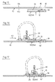
- Figures 15, 16 and 17 show the different phases of assembling the file folder.
- the mounting plate 25 is placed on the outer wall surface 12a of the cover part 12 such that the guide and holding rails 32, 33, 34 reach through the corresponding openings 16, 17, 18 in the cover part 12.
- the clamping and locking device 40 for example in the form of the tab 41 ', passes through the corresponding opening 19 in the cover part 12.
- the aligning device 20 is then pushed in in the direction of the arrow X3 such that its base plate 25 slides in the guide and holding rails 32, 33 (FIG. 16).
- the base plate 25 rests on the guide and holding rail 34 parallel to the longitudinal side of the mounting plate 30, so that a further movement is no longer possible and on the other hand the clamping and locking device 40 snaps into place a corresponding projection of the base plate 25.
- the alignment device 20 with its base plate 25 is firmly attached the cover part 12 of the file folder 10 fixed and attached.
- the line-up device 20 with its base plate 25 is both frictionally attached to the cover part 12 of the file folder 10, which is clamped between the base plate 25 and the mounting plate 30, and also secured by a positive connection.
- the guide and holding rails 32, 33 and 32, 33, 34 are fitted exactly into the corresponding openings 16, 17 and 18 in the cover part of the file folder 10, so that the mounting plate 30 and thus the entire aligning device 20 are properly seated is.
- the file folder 10 can be stacked in a space-saving manner since no components protrude from or out of the lid parts of the folder 10.
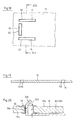
- eyelets 50 are inserted into the openings 16, 17, 18 and also into the opening 19, which correspond to the shape and dimensions of the openings, ie it must be ensured that the guide and holding rails can be passed through even after the eyelets 50 have been inserted into the openings in the cover part 12.
- the opening 19 for the clamping tongue 41 or clamping tab 41 ' can be equipped with an appropriately sized eyelet (FIGS. 18 and 19).
- the eyelets 50 inserted into the openings consist of plastics or metallic materials, in the latter case the flanging of the two circumferential edges of each eyelet 50 takes place by means of pressing pressure in such a way that the flanged edge regions are pressed into the material of the cover part 12 and therefore not in any Comes to protruding parts.
- the height H of the eyelet 50 corresponds approximately to the height of the vertical leg 32a of the guide and holding rail 32, so that the upper angled edge section 32b protrudes from the plane formed by the upper circumferential edge of the eyelet and thus from the inner wall surface 12b of the cover part 12 to form the guide opening 32c for the base plate 25 (FIG. 20).
- a thickness is specified with the eyelet 50, on the basis of which it is always ensured that the guide and holding rails 32 to 34 protruding from the openings 16 to 19 retain their full function for guiding and holding the base plate 25.
- the mounting plate 30 is formed in one piece according to Figures 4 and 10. However, there is also the possibility of forming the mounting plate 30 in two parts, in which case each part of the mounting plate carries the guide and holding rails required for holding the base plate 25 of the aligning device 20.
- the two-part design of the mounting plate 30 is e.g. always come into use when two guide and holding rails, namely the guide and holding rails 32, 33, are considered sufficient for holding the base plate 25.
- the individual plate blanks can have a square, rectangular or circular or some other geometric shape.
- the necessary openings for the passage of the guide and holding rails are provided in the cover part 12 of the file folder 10, which have a square or rectangular cross section and a guide slot running in the longitudinal direction of the rail for the base plate 25, the guide and holding rails the mounting plate 130 are formed in the same way.
- a clamping and locking device 40 can also be used, which is designed, for example, on the guide and holding rail 32 or 33 itself.
- the upper angled edge section 32b of the leg 32a of the guide and holding rail has 32 on its inner wall surface a resilient tongue 41 '', which is designed and arranged so that after pushing the base plate 25 into the guide and holding rails by means of this resilient tongue 41 '' pressure is exerted on the base plate, so that it is held securely in the guide and holding rails.
- clamping and locking device is always advantageous if, by changing the material thickness of the wall parts of the folder 10, the base plate 25 is loosely seated in the guide and holding rails.
- differently designed clamping and locking devices for the base plate 25 can also be provided, for example latching connections or the like.
- the guide and holding rails 32, 33 and 34 are fixedly connected to the mounting plate 30 in the previously described embodiments.
- the mounting plate 30 or 130 with guide and holding rails which are detachably connected to the mounting plate.
- the two guide and holding rails 32, 33 have at least one vertical fastening mandrel 60 on their wall surface facing the mounting plate 30, which engages in a sleeve 61 fastened to the mounting plate 30. It is advantageous if each guide and holding rail has two fastening pins 60 and the mounting plate 30 has a number of sleeves 61 corresponding to the number of pins 60, since the guide and holding rails are secured against twisting due to this configuration.
- Mandrel 60 and sleeve 61 have approximately square or rectangular cross sections, then there is also one Protection against rotation is given when only one mandrel and one sleeve interact.
- Mandrel 60 and sleeve 61 are designed so that the mandrel 60 inserted into the interior of the sleeve 61 is locked against pulling out, for example by means of locking cams or the like, which probably allow insertion of the mandrel 60 into the sleeve 61, but a resistance offer against pulling the mandrels out of the sleeves.
- 23 shows the two guide and holding rails 32, 33 before being inserted into the sleeves 61 on the mounting plate 30, while FIG. 24 shows the guide and holding rails 32, 33 connected to the mounting plate 30.
- the use of guide and holding rails detachably connected to the mounting plate 30 provides the advantage that only small openings are required in the cover part 12 of the folder 10, through which the sleeves 61 of the mounting plate 30 can be passed.
- the length of the sleeves 61 corresponds approximately to the material thickness of the cover part 12. The small openings required then are barely visible when the line-up device is not installed.
- the base plates 25 of the conventional line-up device 20 are designed such that the base plates can engage in the guide openings formed by the guide and holding rails 32 to 34.
- base plates are provided which have no corresponding guide edges, by means of which the base plates can be inserted into the guide and holding rails.
- the base-side sections of these base plates are bent sideways to guide surfaces to obtain, which engage in the guide openings of the guide and holding rails.
- the number of line-up devices 20 fastened to the rear cover part 12 of the folder 10 is in no way limited to only a single line-up device.
- the folder can also be equipped with two lever mechanisms or with three lever mechanisms. In these cases, a number of mounting plates 30 or 130, each of which is provided with guide and holding rails and / or a clamping and locking device 40, is required, corresponding to the number of line-up devices to be attached.
- the rear cover part 12 of the folder then has a number of openings corresponding to the number of guide and holding rails 32 to 34 provided on the mounting plates, through which the guide and holding rails pass when the mounting plates are put on. If the line-up device 20, e.g.
- the openings required for the passage of the guide and holding rails are formed in this back part.
- the mounting plate 30 then placed on the outer wall surface of the back part can at the same time be provided with an insertion pocket 70 made of crystal-clear material for back signs or with a labeling field (FIG. 6).
- the guide and holding rails 32, 33 which can be designed as a resilient engagement leg for the base plate 25, can also be designed in such a way that the guide and holding rail 34, which runs transversely to these guide and holding rails 32, 33, is integrated into the former in this way is that, for example, two L-shaped guide rails 32 ', 33' are used (Fig. 14).
- the cover part 12 then has openings which correspond to the shape of the guide and holding rails.
- the mounting plate 30, 130 can also consist of several individual plate-shaped blanks 30 '(FIG. 22).
- Each panel blank 30 ' has a vertical mandrel 60' which, during assembly, reaches through a corresponding opening in the cover part 12 of the file folder 10 and engages in a corresponding opening in the base plate 125.
- the mandrel 60 ' is locked with the base plate 25, e.g. by means of a screw cap or the like, so that the base plate 25 is held on the cover part 12 by means of the small-area mounting plates 30 'and their spikes 60'.
- These mounting plates 30 'with their thorns, pins or the like. 60 ' can also be rivet-shaped, but with the proviso that the base plate 25 is locked or locked.
- Detachable screw connections can also be used with flat-head screws, the heads of which then form the mounting plates with which the screws rest on the outer wall surface of the cover part 12.
- the writing plate 110 consists of an approximately rectangular plate blank 110a with a clamping mechanism 120 fastened to its upper edge 110b, which is fastened to a base plate 25, the fastening of which to the plate blank 110a takes place by means of the mounting plate 30, 130; the plate blank 110a is provided with slot-shaped openings 16, 17, 18, 19, so that the fastening of the clamping mechanism 120 takes place in accordance with the fastening of the line-up device 20 to the file folder.
- the clamping mechanism 120 of writing folders which consist of a front part and a back part, on the upper edge of which the clamping mechanism is fastened and whose front part is provided with a recess for gripping through the clamping mechanism, is in the same way on the back part held by means of the mounting plate 30, 130
Landscapes
- Sheet Holders (AREA)
- Packaging For Recording Disks (AREA)
- Time Recorders, Dirve Recorders, Access Control (AREA)
- Packages (AREA)
- Medicines Containing Antibodies Or Antigens For Use As Internal Diagnostic Agents (AREA)
- Saccharide Compounds (AREA)
- Holo Graphy (AREA)
- Conveying Record Carriers (AREA)
Applications Claiming Priority (4)
| Application Number | Priority Date | Filing Date | Title |
|---|---|---|---|
| AT2123/90 | 1990-10-22 | ||
| AT212390A AT397065B (de) | 1990-10-22 | 1990-10-22 | Aktenordner mit einer haltevorrichtung für lose, gelochte blätter |
| DE9017047U DE9017047U1 (de) | 1990-12-18 | 1990-12-18 | Aktenordner |
| DE9017047U | 1990-12-18 |
Publications (2)
| Publication Number | Publication Date |
|---|---|
| EP0482354A1 EP0482354A1 (de) | 1992-04-29 |
| EP0482354B1 true EP0482354B1 (de) | 1995-02-01 |
Family
ID=25597742
Family Applications (1)
| Application Number | Title | Priority Date | Filing Date |
|---|---|---|---|
| EP91115920A Expired - Lifetime EP0482354B1 (de) | 1990-10-22 | 1991-09-19 | Aktenordner oder Schreibplatte |
Country Status (8)
| Country | Link |
|---|---|
| EP (1) | EP0482354B1 (cs) |
| AT (1) | ATE117947T1 (cs) |
| CS (1) | CS292491A3 (cs) |
| DE (1) | DE59104477D1 (cs) |
| HU (1) | HU210268B (cs) |
| NO (1) | NO914132L (cs) |
| PL (1) | PL291965A1 (cs) |
| RU (1) | RU2039666C1 (cs) |
Families Citing this family (12)
| Publication number | Priority date | Publication date | Assignee | Title |
|---|---|---|---|---|
| DK75092A (da) * | 1992-06-04 | 1993-12-05 | Hedu Plast A S | Fleksibelt ringbind |
| FR2703952B1 (fr) * | 1993-04-16 | 1995-06-16 | Treillet Jacques | Classeur a levier. |
| DE4314446A1 (de) * | 1993-05-03 | 1994-11-10 | Leitz Louis Kg | Briefordner |
| ATE181533T1 (de) * | 1993-09-08 | 1999-07-15 | Asoma Fashion Gmbh | Haltevorrichtung für eine kipphebelringmechanik |
| RU2129070C1 (ru) * | 1998-08-11 | 1999-04-20 | Казмин Геннадий Тихонович | Устройство для разъемного скрепления и размещения листов с отверстиями |
| GB0005605D0 (en) * | 2000-03-08 | 2000-05-03 | Leco Stationery Mfg | Device for retaining a stack of papers in a file |
| US6511244B1 (en) | 2001-08-13 | 2003-01-28 | C.I.Q. International Ltd. | Binder |
| NL1019739C2 (nl) * | 2002-01-14 | 2003-07-15 | Fountain Tech Bv | Ordner en werkwijze voor aanbieden van ordners. |
| BE1015045A3 (nl) * | 2002-07-18 | 2004-09-07 | Unibind Cyprus Ltd | Accessoire voor een schrijfplaat, map of dergelijke die met zulk accessoire is uitgerust. |
| AT412266B (de) * | 2002-08-23 | 2004-12-27 | Schneider Guenter Karl | Ordnermechanik |
| DE20213605U1 (de) * | 2002-08-29 | 2002-11-28 | Brändle, Martin, Dipl.-Kaufm., 72805 Lichtenstein | Briefordner mit drehbarer Ordnermechanik |
| CN103612507B (zh) * | 2013-12-16 | 2016-01-06 | 东莞市新原文具有限公司 | 一种可拆卸单轴文件夹 |
Family Cites Families (9)
| Publication number | Priority date | Publication date | Assignee | Title |
|---|---|---|---|---|
| DE1536551A1 (de) * | 1967-08-08 | 1970-01-08 | Friedrich Buchner | Schriftgutordner mit Aufreihstiften fuer das aufzubewahrende Schriftgut |
| FR2291042A1 (fr) * | 1974-11-15 | 1976-06-11 | Articles Metalliques Ste Indle | Perfectionnement aux classeurs-relieurs |
| DE2727616A1 (de) * | 1977-06-20 | 1979-01-04 | Erich Seiler | Ordner zum abheften von schriftstuecken |
| DE3013310C2 (de) * | 1980-04-05 | 1983-05-19 | Fa. Xaver Felder, 7634 Kippenheim | Aktenordner |
| US4583877A (en) * | 1984-11-19 | 1986-04-22 | Dennison National Company | Ring binder cover |
| DE3607801C1 (en) * | 1986-03-08 | 1987-06-11 | Leitz Fa Louis | Apparatus for arranging perforated documents in sequence and turning them over |
| US4765768A (en) * | 1987-08-24 | 1988-08-23 | Wright John S | Ring binding mechanism |
| US4763389A (en) * | 1987-10-14 | 1988-08-16 | Chang Shih Ho | Clipboard structure |
| FR2639584A1 (fr) * | 1988-11-29 | 1990-06-01 | Gerriet Jacques | Mecanisme a levier ou similaire pour classeur a anneaux et classeur qui en est equipe |
-
1991
- 1991-09-19 AT AT91115920T patent/ATE117947T1/de not_active IP Right Cessation
- 1991-09-19 DE DE59104477T patent/DE59104477D1/de not_active Expired - Fee Related
- 1991-09-19 EP EP91115920A patent/EP0482354B1/de not_active Expired - Lifetime
- 1991-09-24 CS CS912924A patent/CS292491A3/cs unknown
- 1991-10-08 PL PL29196591A patent/PL291965A1/xx unknown
- 1991-10-16 HU HU913269A patent/HU210268B/hu not_active IP Right Cessation
- 1991-10-21 NO NO91914132A patent/NO914132L/no unknown
- 1991-10-21 RU SU915010069A patent/RU2039666C1/ru active
Also Published As
| Publication number | Publication date |
|---|---|
| ATE117947T1 (de) | 1995-02-15 |
| RU2039666C1 (ru) | 1995-07-20 |
| CS292491A3 (en) | 1992-05-13 |
| PL291965A1 (en) | 1992-06-26 |
| HUT61501A (en) | 1993-01-28 |
| NO914132L (no) | 1992-04-23 |
| HU210268B (en) | 1995-03-28 |
| DE59104477D1 (de) | 1995-03-16 |
| HU913269D0 (en) | 1992-01-28 |
| NO914132D0 (no) | 1991-10-21 |
| EP0482354A1 (de) | 1992-04-29 |
Similar Documents
| Publication | Publication Date | Title |
|---|---|---|
| EP0482354B1 (de) | Aktenordner oder Schreibplatte | |
| EP0286987A1 (de) | Vorrichtung zum Aufbewahren von Datendisketten in Aktenordnern | |
| CH683421A5 (de) | Vorrichtung zur Aufnahme eines Klebzettelblocks. | |
| DE3410974A1 (de) | Deckenbefestigung fuer dekorationselemente und dergleichen | |
| DE2302365A1 (de) | Aufreihystem fuer gelochte papierstapel oder dergl. in heftern, mappen und aehnlichen registratursammlern | |
| DE8803353U1 (de) | Schnellhefter | |
| DE2644824B2 (de) | Hangemappe | |
| DE2656021C3 (de) | Briefordner zur Aufnahme von gelochtem Schriftgut | |
| DE2206662B2 (de) | Blatthalter | |
| EP1632146B1 (de) | Behältnis für ein Geometriedreieck und Flachmaterialstreifen zum Herstellen des Behältnisses | |
| EP0219775A1 (de) | Ordner für Papierbögen, insbesondere EDV-Papierbögen | |
| DE69904196T2 (de) | Ordner | |
| EP0160740B1 (de) | Ordner für Papierbögen oder dergleichen | |
| DE9017047U1 (de) | Aktenordner | |
| DE3441050C2 (cs) | ||
| DE69300983T2 (de) | Einstückigen Körper für Heftgerät oder Brieflocher | |
| EP0505697A2 (de) | Rückenschildhalter für Briefordner | |
| EP0729851B1 (de) | Schnellhefter | |
| EP0983869B1 (de) | Hängeschiene | |
| EP0520189B1 (de) | Ordnermechanik | |
| EP1138523B1 (de) | Hefteinrichtung für Schnellhefter, Ordner oder Ringbuch | |
| EP0956206B1 (de) | Hängemappe | |
| DE3341175C1 (de) | Ordner für Papierbögen, insbesondere für EDV-Papierbögen | |
| DE68907018T2 (de) | Haengeordner mit seitlichem oder vertikalem zugang. | |
| DE9116259U1 (de) | Aktenordner |
Legal Events
| Date | Code | Title | Description |
|---|---|---|---|
| PUAI | Public reference made under article 153(3) epc to a published international application that has entered the european phase |
Free format text: ORIGINAL CODE: 0009012 |
|
| AK | Designated contracting states |
Kind code of ref document: A1 Designated state(s): AT BE CH DE DK ES FR GB GR IT LI NL SE |
|
| 17P | Request for examination filed |
Effective date: 19920821 |
|
| 17Q | First examination report despatched |
Effective date: 19930716 |
|
| GRAA | (expected) grant |
Free format text: ORIGINAL CODE: 0009210 |
|
| AK | Designated contracting states |
Kind code of ref document: B1 Designated state(s): AT BE CH DE DK ES FR GB GR IT LI NL SE |
|
| PG25 | Lapsed in a contracting state [announced via postgrant information from national office to epo] |
Ref country code: GR Free format text: LAPSE BECAUSE OF FAILURE TO SUBMIT A TRANSLATION OF THE DESCRIPTION OR TO PAY THE FEE WITHIN THE PRESCRIBED TIME-LIMIT Effective date: 19950201 Ref country code: GB Effective date: 19950201 Ref country code: ES Free format text: THE PATENT HAS BEEN ANNULLED BY A DECISION OF A NATIONAL AUTHORITY Effective date: 19950201 Ref country code: DK Effective date: 19950201 Ref country code: BE Effective date: 19950201 |
|
| REF | Corresponds to: |
Ref document number: 117947 Country of ref document: AT Date of ref document: 19950215 Kind code of ref document: T |
|
| ITF | It: translation for a ep patent filed | ||
| REF | Corresponds to: |
Ref document number: 59104477 Country of ref document: DE Date of ref document: 19950316 |
|
| ET | Fr: translation filed | ||
| PG25 | Lapsed in a contracting state [announced via postgrant information from national office to epo] |
Ref country code: SE Effective date: 19950501 |
|
| GBV | Gb: ep patent (uk) treated as always having been void in accordance with gb section 77(7)/1977 [no translation filed] |
Effective date: 19950201 |
|
| PG25 | Lapsed in a contracting state [announced via postgrant information from national office to epo] |
Ref country code: AT Effective date: 19950919 |
|
| PG25 | Lapsed in a contracting state [announced via postgrant information from national office to epo] |
Ref country code: LI Effective date: 19950930 Ref country code: CH Effective date: 19950930 |
|
| PLBE | No opposition filed within time limit |
Free format text: ORIGINAL CODE: 0009261 |
|
| STAA | Information on the status of an ep patent application or granted ep patent |
Free format text: STATUS: NO OPPOSITION FILED WITHIN TIME LIMIT |
|
| 26N | No opposition filed | ||
| REG | Reference to a national code |
Ref country code: CH Ref legal event code: PL |
|
| PG25 | Lapsed in a contracting state [announced via postgrant information from national office to epo] |
Ref country code: FR Effective date: 19960531 |
|
| REG | Reference to a national code |
Ref country code: FR Ref legal event code: ST |
|
| PGFP | Annual fee paid to national office [announced via postgrant information from national office to epo] |
Ref country code: DE Payment date: 20030909 Year of fee payment: 13 |
|
| PGFP | Annual fee paid to national office [announced via postgrant information from national office to epo] |
Ref country code: NL Payment date: 20030917 Year of fee payment: 13 |
|
| PG25 | Lapsed in a contracting state [announced via postgrant information from national office to epo] |
Ref country code: NL Free format text: LAPSE BECAUSE OF NON-PAYMENT OF DUE FEES Effective date: 20050401 Ref country code: DE Free format text: LAPSE BECAUSE OF NON-PAYMENT OF DUE FEES Effective date: 20050401 |
|
| NLV4 | Nl: lapsed or anulled due to non-payment of the annual fee |
Effective date: 20050401 |
|
| PG25 | Lapsed in a contracting state [announced via postgrant information from national office to epo] |
Ref country code: IT Free format text: LAPSE BECAUSE OF NON-PAYMENT OF DUE FEES;WARNING: LAPSES OF ITALIAN PATENTS WITH EFFECTIVE DATE BEFORE 2007 MAY HAVE OCCURRED AT ANY TIME BEFORE 2007. THE CORRECT EFFECTIVE DATE MAY BE DIFFERENT FROM THE ONE RECORDED. Effective date: 20050919 |