EP0482472B1 - Dispositif pour la transmission optique de données entre satellites - Google Patents
Dispositif pour la transmission optique de données entre satellites Download PDFInfo
- Publication number
- EP0482472B1 EP0482472B1 EP91117527A EP91117527A EP0482472B1 EP 0482472 B1 EP0482472 B1 EP 0482472B1 EP 91117527 A EP91117527 A EP 91117527A EP 91117527 A EP91117527 A EP 91117527A EP 0482472 B1 EP0482472 B1 EP 0482472B1
- Authority
- EP
- European Patent Office
- Prior art keywords
- detector
- arrangement
- satellites
- position detector
- information
- Prior art date
- Legal status (The legal status is an assumption and is not a legal conclusion. Google has not performed a legal analysis and makes no representation as to the accuracy of the status listed.)
- Expired - Lifetime
Links
- 230000003287 optical effect Effects 0.000 title claims description 11
- 230000005540 biological transmission Effects 0.000 title claims description 6
- 238000004891 communication Methods 0.000 claims description 6
- 239000013078 crystal Substances 0.000 claims description 2
- 238000012545 processing Methods 0.000 claims description 2
- 239000004020 conductor Substances 0.000 claims 1
- 238000001514 detection method Methods 0.000 description 4
- 239000000463 material Substances 0.000 description 3
- 239000013307 optical fiber Substances 0.000 description 3
- 230000032683 aging Effects 0.000 description 2
- 230000015556 catabolic process Effects 0.000 description 1
- 238000006731 degradation reaction Methods 0.000 description 1
- 230000001419 dependent effect Effects 0.000 description 1
- 230000006866 deterioration Effects 0.000 description 1
- 238000011161 development Methods 0.000 description 1
- 230000018109 developmental process Effects 0.000 description 1
- 230000000694 effects Effects 0.000 description 1
- 238000011156 evaluation Methods 0.000 description 1
- 238000000034 method Methods 0.000 description 1
- 230000005693 optoelectronics Effects 0.000 description 1
- 230000035945 sensitivity Effects 0.000 description 1
- 238000012546 transfer Methods 0.000 description 1
Images
Classifications
-
- H—ELECTRICITY
- H04—ELECTRIC COMMUNICATION TECHNIQUE
- H04B—TRANSMISSION
- H04B10/00—Transmission systems employing electromagnetic waves other than radio-waves, e.g. infrared, visible or ultraviolet light, or employing corpuscular radiation, e.g. quantum communication
- H04B10/11—Arrangements specific to free-space transmission, i.e. transmission through air or vacuum
- H04B10/118—Arrangements specific to free-space transmission, i.e. transmission through air or vacuum specially adapted for satellite communication
Definitions
- the invention relates to an arrangement for optical communication between satellites with a position detector, which is used to determine the angular error between transmitter and receiver, and an information detector, which is used to process the transmitted message.
- the receiving satellite needs to align its antenna, i.e. of the telescope, the information about its position relative to the transmitting satellite. This is obtained either by evaluating the degradation of the received data signal or by special detectors.
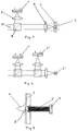
- the tracking takes place in such a way that the received light beam always hits the center of the position detector (2 ') and thus also the information detector (3') is hit.
- two detectors are therefore provided which cover different angular ranges with an adapted resolution in order to enable the alignment of the telescope.
- the relative alignment between position detector (2 ') and information detector (3') must be very precise. This is the only way to transfer maximum power.
- the size of the information detector is determined by the uncertainty of the relative alignment between the two detectors.
- an excessively large field of vision of the information detector leads to an increase in the received background power and thus to an increase in the disturbing noise level.
- the very high stability requirements for the assembly of the detector systems can only be met with selected materials for the supporting structure and complex temperature control. Nevertheless, temperature changes and aging of the materials can cause changes in the relative alignment between the position detector and the information detector.
- the problems described above can be alleviated by combining the position detector and the information detector. This means that the two detectors do not have to be aligned with one another. Changes in temperature and age do not affect the alignment of the two detectors. An optical system can also be saved.
- FIG. 1 shows how the optical processing of a received light beam 10 takes place in a received satellite.
- the received light beam 10 first strikes a beam splitter 7.
- a beam splitter which acts as a power splitter
- an arrangement with a perforated mirror can be used, for example, which the beam depends on Splits the angle of incidence.
- part of the received light beam is focused on a detector 1 with a lens 8.
- a rough directional control is carried out with the information about the position of the focus spot from the detection detector 1.
- the main part of the received light 10 is focused via a lens 9 on the combination of position detector 2 and information detector 3. While the inner part of the focus spot is being coupled into the information detector 3, the outer edge of the focus spot falls on the position detector.
- position detector 2 All known detector types such as four-quadrant diodes, position-sensitive surface diodes (PSD) or detectors with many individual elements (CCD) can be used as position detector 2.
- the position detector 2 must have a recess 6 in its center.
- the information detector 3 can be constructed in the same crystal as the position detector 2, ie monolithically, or directly behind it. But it is also possible that in the recess of the position detector 2 there is an optical fiber 5 which leads to the actual receiver, the information detector (FIG. 3).
- the division of the received optical power 4 which is indicated in FIG. 3 with an identity distribution, can take place through the appropriate choice of the geometries, ie the diameter of the recess 6, and the distance between the lens 9 and the position detector 2.
- the information detector can either be connected directly to the position detector or is via a Optical fiber coupled to the recess in the position detector.
- the high stability requirements for the angle between position and information detector are easily met by the arrangement according to the invention.
- a deterioration in the resolution of the position detector due to the recess provided therein is not to be expected.
- An improvement in the reception sensitivity of the information detector can be achieved.
- the optics in the receiving branch are simplified, since the received light only needs to be focused on the combined detector and no longer individually on both detectors.
Landscapes
- Physics & Mathematics (AREA)
- Astronomy & Astrophysics (AREA)
- General Physics & Mathematics (AREA)
- Electromagnetism (AREA)
- Engineering & Computer Science (AREA)
- Computer Networks & Wireless Communication (AREA)
- Signal Processing (AREA)
- Optical Communication System (AREA)
Claims (3)
- Dispositif pour la transmission optique d'information entre satellites, qui comprennent une partie réception équipée d'un détecteur de position (2), servant à déterminer l'erreur angulaire entre émetteur et récepteur, et d'un détecteur d'information (3) qui sert à traiter l'information transmise, caractérisé en ce que le détecteur de position (2) présente en son milieu un évidement (6) dans lequel ou auquel est fixé, soit un guide d'onde optique (5), lequel est relié au détecteur d'information (3), soit le détecteur d'information (3).
- Dispositif pour la transmission optique d'information entre satellites selon la revendication 1, caractérisé en ce que le détecteur d'information (3) et le détecteur de position (2) sont réalisés dans le même cristal.
- Dispositif pour la transmission optique d'information entre satellites selon la revendication 1 ou 2, caractérisé en ce que le détecteur de position (3) est une diode à quatre quadrants, une diode à jonction à sensibilité de position ou un détecteur comprenant de nombreux éléments individuels (tel qu'un dispositif à couplage de charge (CCD)).
Applications Claiming Priority (2)
| Application Number | Priority Date | Filing Date | Title |
|---|---|---|---|
| DE4033776 | 1990-10-24 | ||
| DE4033776A DE4033776A1 (de) | 1990-10-24 | 1990-10-24 | Anordnung zur optischen nachrichtenuebertragung zwischen satelliten |
Publications (3)
| Publication Number | Publication Date |
|---|---|
| EP0482472A2 EP0482472A2 (fr) | 1992-04-29 |
| EP0482472A3 EP0482472A3 (en) | 1992-10-21 |
| EP0482472B1 true EP0482472B1 (fr) | 1995-05-24 |
Family
ID=6416938
Family Applications (1)
| Application Number | Title | Priority Date | Filing Date |
|---|---|---|---|
| EP91117527A Expired - Lifetime EP0482472B1 (fr) | 1990-10-24 | 1991-10-15 | Dispositif pour la transmission optique de données entre satellites |
Country Status (2)
| Country | Link |
|---|---|
| EP (1) | EP0482472B1 (fr) |
| DE (2) | DE4033776A1 (fr) |
Cited By (4)
| Publication number | Priority date | Publication date | Assignee | Title |
|---|---|---|---|---|
| US7224508B2 (en) | 2004-09-13 | 2007-05-29 | Space Photonics, Inc. | MEMS-based optical communications beam steering apparatus |
| US7612317B2 (en) | 2004-09-13 | 2009-11-03 | Space Photonics, Inc. | Beam steering for optical target identification and tracking without gimbals or scanning mirrors |
| US7612329B2 (en) | 2004-09-13 | 2009-11-03 | Space Photonics, Inc. | Apparatus and method for free space optical communications beam steering without gimbals |
| US8160452B1 (en) | 2008-01-07 | 2012-04-17 | Space Photonics, Inc. | Rapid acquisition, pointing and tracking optical system for free space optical communications |
Families Citing this family (14)
| Publication number | Priority date | Publication date | Assignee | Title |
|---|---|---|---|---|
| DE4239863A1 (en) * | 1992-11-27 | 1993-04-29 | Gerd Sauer | Optical data transmitter for car traffic - has photosensitive sensor with optical focussing OS reception beam, and directional control |
| DE4325426C2 (de) * | 1993-03-15 | 1999-04-15 | Heinrich Dr Ing Iglseder | Verfahren und Vorrichtung zur Übertragung von Informationen vom Weltraum aus auf die Erde |
| US5949594A (en) * | 1993-07-29 | 1999-09-07 | Iglseder; Heinrich | Process for the generation of information in space |
| JP3672202B2 (ja) * | 1993-09-08 | 2005-07-20 | シャープ株式会社 | 空間光伝送装置及び空間光伝送方法 |
| DE19847480A1 (de) | 1998-10-15 | 2000-04-27 | Daimler Chrysler Ag | Verfahren und Vorrichtung zur Lagebestimmung von Kommunikations-Satelliten |
| US6219593B1 (en) | 1999-03-01 | 2001-04-17 | Motorola, Inc. | Method and apparatus for attitude determination in a multi-nodal system |
| US6522440B1 (en) | 1999-04-28 | 2003-02-18 | Trw Inc. | Inter-satellite optical link track sensor |
| US6469815B1 (en) | 1999-04-28 | 2002-10-22 | Trw Inc. | Inter-satellite optical link acquisition sensor |
| US6957020B2 (en) | 1999-07-07 | 2005-10-18 | Northrop Grumman Corporation | Optical inter-satellite link (OISL) gimbal |
| US6535314B1 (en) | 2000-01-13 | 2003-03-18 | Trw Inc. | Satellite optical communication beam acquisition techniques |
| US6327065B1 (en) | 2000-01-13 | 2001-12-04 | Trw Inc. | Fine pointing assembly configuration |
| US6590685B1 (en) | 2000-01-13 | 2003-07-08 | Northrop Grumman Corporation | Satellite communication optical beam acquisition techniques using a plurality of scan patterns |
| EP1199822A3 (fr) * | 2000-10-05 | 2002-05-02 | Lucent Technologies Inc. | Télescope pour un système de communication optique sans fil en espace libre |
| US7379674B2 (en) | 2003-03-27 | 2008-05-27 | Canon Kabushiki Kaisha | Optical transmission device |
Family Cites Families (2)
| Publication number | Priority date | Publication date | Assignee | Title |
|---|---|---|---|---|
| DE2629356C2 (de) * | 1976-06-30 | 1983-07-21 | AEG-Telefunken Nachrichtentechnik GmbH, 7150 Backnang | Elektrooptischer Wandler zum Senden oder Empfangen |
| WO1990008433A1 (fr) * | 1989-01-23 | 1990-07-26 | Massachusetts Institute Of Technology | Recepteur a fibre optique |
-
1990
- 1990-10-24 DE DE4033776A patent/DE4033776A1/de not_active Withdrawn
-
1991
- 1991-10-15 EP EP91117527A patent/EP0482472B1/fr not_active Expired - Lifetime
- 1991-10-15 DE DE59105574T patent/DE59105574D1/de not_active Expired - Fee Related
Cited By (4)
| Publication number | Priority date | Publication date | Assignee | Title |
|---|---|---|---|---|
| US7224508B2 (en) | 2004-09-13 | 2007-05-29 | Space Photonics, Inc. | MEMS-based optical communications beam steering apparatus |
| US7612317B2 (en) | 2004-09-13 | 2009-11-03 | Space Photonics, Inc. | Beam steering for optical target identification and tracking without gimbals or scanning mirrors |
| US7612329B2 (en) | 2004-09-13 | 2009-11-03 | Space Photonics, Inc. | Apparatus and method for free space optical communications beam steering without gimbals |
| US8160452B1 (en) | 2008-01-07 | 2012-04-17 | Space Photonics, Inc. | Rapid acquisition, pointing and tracking optical system for free space optical communications |
Also Published As
| Publication number | Publication date |
|---|---|
| EP0482472A2 (fr) | 1992-04-29 |
| DE4033776A1 (de) | 1992-05-07 |
| EP0482472A3 (en) | 1992-10-21 |
| DE59105574D1 (de) | 1995-06-29 |
Similar Documents
| Publication | Publication Date | Title |
|---|---|---|
| EP0482472B1 (fr) | Dispositif pour la transmission optique de données entre satellites | |
| DE60124442T2 (de) | Erfassungstechniken für optische Satellitenkommunikation | |
| DE60033366T2 (de) | Erfassungstechnik des optischen Strahls in der Satellitenkommunikation mit mehreren Abtastmustern | |
| DE69405414T2 (de) | Ausrichtungseinstellsystem zur Verwendung in einem optischen Sende- und Empfangssystem | |
| EP3837779B1 (fr) | Structure de réception d'un signal de données optique | |
| EP1242829B1 (fr) | Systeme mobile et procede pour caracteriser de maniere etendue et precise des champs de rayonnement a l'exterieur | |
| EP2427975B1 (fr) | Dispositif de communication hybride pour une transmission de données haut débit entre des plates-formes mobiles et/ou fixes | |
| EP1890168A1 (fr) | Scanner à laser | |
| DE102014018278B4 (de) | Drehlagen-Bestimmung eines Sensors mittels eines von einem Satelliten ausgestrahlten Laserstrahls | |
| EP0831604B1 (fr) | Procédé et dispositif de contrÔle de position de deux ondes lumineuses en cas de réception hétérodyne cohérente | |
| EP0844748A1 (fr) | Procédé et appareil de transmission optique de données sur un trajet en espace libre | |
| EP2073404A1 (fr) | Procédé destiné à la transmission de données optique dans un espace libre et système destiné à l'exécution du procédé | |
| EP1111816B1 (fr) | Méthode et dispositif d'établissement de connexion entre satellites | |
| DE102007006414B4 (de) | Vorrichtung zur Grobausrichtung eines optischen Freiraumstrahls | |
| DE102010034065B4 (de) | Verfahren und System zum Nachführen zweier Kommunikationsteilnehmer eines optischen Satelliten-Kommunikationssystems | |
| DE102005033422B4 (de) | Einrichtung zur zweiseitigen optischen Kommunikation | |
| EP1806858B1 (fr) | Système pour transmission d'espace libre de données entre des terminaux de communication | |
| DE2714177C2 (de) | Azimutal-richtbare optische Sendeeinrichtung | |
| DE19512966C2 (de) | Verfahren zum Gewinnen von Fehlersignalen für eine räumliche Strahlregelung eines optischen Überlagerungsempfängers und Einrichtung zu dessen Durchführung | |
| DE102017215671A1 (de) | Scansystem und Sende- und Empfangsvorrichtung für ein Scansystem | |
| DE102019213521A1 (de) | Aufbau zum Empfangen eines optischen Datensignals | |
| DE846708C (de) | Anordnung zur UEbertragung von Nachrichten ueber Funkricht-verbindungen | |
| DE19713336C1 (de) | Ortsempfindlicher fotoelektrischer Sensor | |
| DE202007012193U1 (de) | Vorrichtung für ein optisches Freiraum-Übertragungssystem und Freiraumübertragungssystem | |
| DE19857974B4 (de) | Einrichtung zur Detektion der Position eines optischen Strahlenbündels |
Legal Events
| Date | Code | Title | Description |
|---|---|---|---|
| PUAI | Public reference made under article 153(3) epc to a published international application that has entered the european phase |
Free format text: ORIGINAL CODE: 0009012 |
|
| AK | Designated contracting states |
Kind code of ref document: A2 Designated state(s): DE FR GB IT NL |
|
| PUAL | Search report despatched |
Free format text: ORIGINAL CODE: 0009013 |
|
| AK | Designated contracting states |
Kind code of ref document: A3 Designated state(s): DE FR GB IT NL |
|
| 17P | Request for examination filed |
Effective date: 19920923 |
|
| 17Q | First examination report despatched |
Effective date: 19940919 |
|
| GRAA | (expected) grant |
Free format text: ORIGINAL CODE: 0009210 |
|
| ITF | It: translation for a ep patent filed | ||
| AK | Designated contracting states |
Kind code of ref document: B1 Designated state(s): DE FR GB IT NL |
|
| REF | Corresponds to: |
Ref document number: 59105574 Country of ref document: DE Date of ref document: 19950629 |
|
| ET | Fr: translation filed | ||
| GBT | Gb: translation of ep patent filed (gb section 77(6)(a)/1977) |
Effective date: 19950829 |
|
| PGFP | Annual fee paid to national office [announced via postgrant information from national office to epo] |
Ref country code: GB Payment date: 19951004 Year of fee payment: 5 |
|
| PGFP | Annual fee paid to national office [announced via postgrant information from national office to epo] |
Ref country code: FR Payment date: 19951018 Year of fee payment: 5 |
|
| PGFP | Annual fee paid to national office [announced via postgrant information from national office to epo] |
Ref country code: DE Payment date: 19951218 Year of fee payment: 5 |
|
| PLBE | No opposition filed within time limit |
Free format text: ORIGINAL CODE: 0009261 |
|
| STAA | Information on the status of an ep patent application or granted ep patent |
Free format text: STATUS: NO OPPOSITION FILED WITHIN TIME LIMIT |
|
| 26N | No opposition filed | ||
| PG25 | Lapsed in a contracting state [announced via postgrant information from national office to epo] |
Ref country code: GB Effective date: 19961015 |
|
| PGFP | Annual fee paid to national office [announced via postgrant information from national office to epo] |
Ref country code: NL Payment date: 19961022 Year of fee payment: 6 |
|
| GBPC | Gb: european patent ceased through non-payment of renewal fee |
Effective date: 19961015 |
|
| PG25 | Lapsed in a contracting state [announced via postgrant information from national office to epo] |
Ref country code: FR Effective date: 19970630 |
|
| PG25 | Lapsed in a contracting state [announced via postgrant information from national office to epo] |
Ref country code: DE Effective date: 19970701 |
|
| REG | Reference to a national code |
Ref country code: FR Ref legal event code: ST |
|
| PG25 | Lapsed in a contracting state [announced via postgrant information from national office to epo] |
Ref country code: NL Free format text: LAPSE BECAUSE OF NON-PAYMENT OF DUE FEES Effective date: 19980501 |
|
| NLV4 | Nl: lapsed or anulled due to non-payment of the annual fee |
Effective date: 19980501 |
|
| PG25 | Lapsed in a contracting state [announced via postgrant information from national office to epo] |
Ref country code: IT Free format text: LAPSE BECAUSE OF NON-PAYMENT OF DUE FEES;WARNING: LAPSES OF ITALIAN PATENTS WITH EFFECTIVE DATE BEFORE 2007 MAY HAVE OCCURRED AT ANY TIME BEFORE 2007. THE CORRECT EFFECTIVE DATE MAY BE DIFFERENT FROM THE ONE RECORDED. Effective date: 20051015 |