EP0482503B1 - Mobiles Funkkommunikationssystem mit mobiler Basisstation und tragbares Gerät als Mobilstation - Google Patents
Mobiles Funkkommunikationssystem mit mobiler Basisstation und tragbares Gerät als Mobilstation Download PDFInfo
- Publication number
- EP0482503B1 EP0482503B1 EP91117668A EP91117668A EP0482503B1 EP 0482503 B1 EP0482503 B1 EP 0482503B1 EP 91117668 A EP91117668 A EP 91117668A EP 91117668 A EP91117668 A EP 91117668A EP 0482503 B1 EP0482503 B1 EP 0482503B1
- Authority
- EP
- European Patent Office
- Prior art keywords
- radio
- radio channel
- mobile base
- mobile
- mss
- Prior art date
- Legal status (The legal status is an assumption and is not a legal conclusion. Google has not performed a legal analysis and makes no representation as to the accuracy of the status listed.)
- Expired - Lifetime
Links
- 238000004891 communication Methods 0.000 title claims description 112
- 230000005540 biological transmission Effects 0.000 claims description 71
- 238000000034 method Methods 0.000 claims description 25
- 102100039300 Phosphatidylserine synthase 2 Human genes 0.000 claims description 18
- 101710138332 Somatostatin-2 Proteins 0.000 claims description 18
- 102100039298 Phosphatidylserine synthase 1 Human genes 0.000 claims description 13
- 101710138331 Somatostatin-1 Proteins 0.000 claims description 13
- 230000002123 temporal effect Effects 0.000 claims 1
- 230000010355 oscillation Effects 0.000 description 13
- 238000010586 diagram Methods 0.000 description 10
- 230000008054 signal transmission Effects 0.000 description 10
- 230000005684 electric field Effects 0.000 description 9
- 230000001413 cellular effect Effects 0.000 description 3
- 238000006243 chemical reaction Methods 0.000 description 3
- 230000011664 signaling Effects 0.000 description 3
- VYLDEYYOISNGST-UHFFFAOYSA-N bissulfosuccinimidyl suberate Chemical compound O=C1C(S(=O)(=O)O)CC(=O)N1OC(=O)CCCCCCC(=O)ON1C(=O)C(S(O)(=O)=O)CC1=O VYLDEYYOISNGST-UHFFFAOYSA-N 0.000 description 2
- 238000005265 energy consumption Methods 0.000 description 2
- 230000001360 synchronised effect Effects 0.000 description 2
- 101001090865 Homo sapiens 26S proteasome regulatory subunit 7 Proteins 0.000 description 1
- 101000828889 Homo sapiens tRNA modification GTPase GTPBP3, mitochondrial Proteins 0.000 description 1
- 230000003111 delayed effect Effects 0.000 description 1
- 230000004069 differentiation Effects 0.000 description 1
- 230000000694 effects Effects 0.000 description 1
- 238000005562 fading Methods 0.000 description 1
- 238000009434 installation Methods 0.000 description 1
- 239000007788 liquid Substances 0.000 description 1
- 230000002093 peripheral effect Effects 0.000 description 1
- 230000010363 phase shift Effects 0.000 description 1
- 230000001144 postural effect Effects 0.000 description 1
- 102100023793 tRNA modification GTPase GTPBP3, mitochondrial Human genes 0.000 description 1
Images


Classifications
-
- H—ELECTRICITY
- H04—ELECTRIC COMMUNICATION TECHNIQUE
- H04W—WIRELESS COMMUNICATION NETWORKS
- H04W88/00—Devices specially adapted for wireless communication networks, e.g. terminals, base stations or access point devices
- H04W88/08—Access point devices
-
- H—ELECTRICITY
- H04—ELECTRIC COMMUNICATION TECHNIQUE
- H04W—WIRELESS COMMUNICATION NETWORKS
- H04W88/00—Devices specially adapted for wireless communication networks, e.g. terminals, base stations or access point devices
- H04W88/08—Access point devices
- H04W88/085—Access point devices with remote components
-
- H—ELECTRICITY
- H04—ELECTRIC COMMUNICATION TECHNIQUE
- H04B—TRANSMISSION
- H04B7/00—Radio transmission systems, i.e. using radiation field
- H04B7/24—Radio transmission systems, i.e. using radiation field for communication between two or more posts
- H04B7/26—Radio transmission systems, i.e. using radiation field for communication between two or more posts at least one of which is mobile
- H04B7/2603—Arrangements for wireless physical layer control
- H04B7/2606—Arrangements for base station coverage control, e.g. by using relays in tunnels
Definitions
- the curled cord can constitutes an annoying obstacle when the driver drives and speaks into the telephone transmitter simultaneously.
- the handset cannot be moved away beyond a limit posed by the curled wire, meaning that a passenger sitting on the front or rear passenger seat is compelled to stand up or take a crouching posture if he or she wants to speak over the phone.
- the automobile telephone main unit While the handset assembly of a conventional mobile station is placed within the passenger cabin of a car, the automobile telephone main unit is normally arranged in the trunk of the car.
- the signal cord connecting the telephone main unit and the handset assembly should be carefully arranged so as not to aesthetically damage the appearance of the car, entailing a troublesome work to be done within a narrow space of the car.
- Fig. 1 shows a schematic view of a first embodiment of the mobile radio communication system of the invention, which is an automobile telephone system.
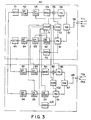
- the transmission system comprises a telephone transmitter 11, a speech encoder (SPCOD) 12, an error correction encoder (CHCOD) 13, a digital modulator (MOD) 14, a multiplier 15, a power amplifier (PA) 16, a high frequency switch circuit (SW) 17 and an antenna 18.
- the speech encoder 12 encodes analog speech signals coming from the telephone transmitter 11 into coded signals.
- the error correction encoder 13 detects and corrects errors in coded speech signals coming from the speech encoder 12 and encoding control signals coming from a control circuit 31, which will be described later.
- the digital modulator 14 generates intermediate frequency signals and causes them to be modulated by encoded speech signals coming from the error correction encoder 13 before sending them out.
- the control circuit is normally a microcomputer that comprises a central processing unit (CPU), an input port, an output port, a program ROM and a data RAM.
- the CPU executes control operations according to the programs stored in the program ROM.
- the reception system comprises a receiver (RX) 91, a digital demodulator (DEM) 92, an error correction decoder (CHDEC) 93 and a speech decoder (SPDEC).
- the control system comprises a frequency synthesizer 102 and a received electric field strength sensor circuit 103.
- the frequency synthesizer 102 generates under the control of the control circuit 71 an oscillation having a local oscillation frequency required for radio communication with its portable device PSS.
- the received electric field strength sensor circuit 103 senses the received field strength of the electric wave transmitted from the portable device PSS and sends signals representing the determined field strength to the control circuit 71.
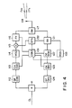
- a base station BSS comprises, like a portable device PSS described above, a transmission system, a reception system, a control system and additionally a hybrid circuit 111, which is used for connecting the transmission system and the reception system to a cable line CL.
- control system comprises a control circuit (CONT) 131, a frequency synthesizer (SYS) 132 and a received electric field strength sensor circuit (RSSI) 133.
- the control circuit 131 has a main control section which is normally a microcomputer and executes control operations for connecting the base station BSS with a first radio channel.
- the frequency synthesizer 132 generates under the control of the control circuit 131 an oscillation having a local oscillation frequency that matches the radio channel specified by the control circuit 131.
- the received electric field strength sensor circuit 133 senses the received field strength of the electric wave transmitted from the mobile base device MSS and sends signals representing the determined field strength to the control circuit 131.
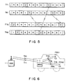
- radio frequency fR1 has an idle time slot as a result of the search operation. Then, the mobile base device MSS detects a synchronous word out of the signals being received through time slot TS1 which is currently busy in the radio frequency fR1 and determines the position of the idle time slot, say time slot TS2, referring to the position of the synchronous word.
- the data for the position of the idle time slot TS2 as well as the date for the radio frequency fR1 are stored in the RAM of the control circuit 71.
- the base station BSS2 or any base station in general which is in a standby state, constantly monitors incoming call signals from the wired telephone network NW and call signals originating from any of the mobile stations MS1 through MSm it covers. If, now, it detects a call signal originating from the mobile base device of mobile station MS2 under this condition, the base station BSS2 generates an answer signal containing the ID code of the calling mobile base device MSS and sends it to the mobile base device MSS by way of the control channel C-CH.
- the mobile base device MSS If, on the other hand, the mobile base device MSS does not receive an answer signal with a predetermined period of time after the transmission of the call signal, it judges that the tried radio frequency and time slot are busy and are not currently available to establish a telephone channel. It then goes on the operation of searching an idle time radio frequency and an idle time slot.
- the base station BSS2 and the mobile base device MSS of the mobile station MS2 are mutually connected by way of a first radio channel having radio frequencies fT1 and fR1 and time slot TS2 available for telephone communication between the two stations.
- the mobile portable device MSS After selecting the time slot TS2 for signal transmission, the mobile portable device MSS generates an answer signal that contains data for specifying the time slot TS2 and the radio frequency fTA for signal transmission and the ID code of the portable device PSS and send it to the portable device PSS by way of the control channel. After sending the answer signal, it controls its reception and transmission systems in such a manner that it operates for signal transmission during the transmission time period of time slots TS2 that follows and signal reception during the reception time period of time slots that follows.
- the portable device PSS at the other end of the control channel waits for the answer signal from the mobile base device MSS, observing a predetermined period of time from the transmission of the call signal. If it receives the answer signal within the predetermined period of time from the transmission of the call signal, it controls the transmission and reception systems on the basis of the data for specifying the radio channel contained in the answer signal in such a way that signals are sent out only during the allocated transmission time period of time slots TS2 of the assigned radio frequency fTA and it receives signals only during the allocated time period of time slots TS2 of the assigned radio frequency fRA.
- the portable device PSS2 transmits a call signal to the mobile base device MSS by way of the control channel.
- the mobile base device MSS constantly monitors incoming call signals except when it receives radio signals from the first portable device PSS1. If the call signal from the second portable device PSS2 arrives under this condition, the mobile base device MSS starts an operation of assigning a radio channel to the portable device PSS2.
- the portable device PSS2 at the other end of the control channel waits for the answer signal from the mobile base device MSS, observing a predetermined period of time from the transmission of the call signal. If it receives the answer signal within the predetermined period of time from the transmission of the call signal, it controls the transmission and reception systems on the basis of the data for specifying a channel contained in the answer signal in such a way that it receives signals only during the allocated time period of time slots TS4 of the assigned radio frequency fTA and signals are sent out from it only during the allocated transmission time period of time slots TS5 of the assigned radio frequency fRA.
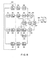
- a radio signal transmitted by the portable device by way of a reception time slot of a second radio channel is received by the receiver 161 by way of the antenna 158 and the high frequency switch 157 in said reception time slot and then demodulated by digital demodulator 92.
- the demodulated digital speech signal is corrected for errors by error correction decoder 93, read out during the transmission time slot for signal transmission to the base station and converted for speed by the speech decoder 52 before it is corrected for errors by error correction encoder 53 and converted into modulated signal by the digital modulated 54.
- the modulated signal is then mixed with a local oscillation signal generated by the frequency synthesizer in the multiplier 155 to become a radio transmission signal.
- the overall configuration of the mobile base device is very simplified so that it may be made very compact and light weight.
- a FDMA/TDMA technique is employed for radio channels connecting base stations and mobile base devices as well as mobile base devices and portable devices
- a FDMA or TDMA technique may be used in its place.
- a FDMA/TDMA technique may be used for connection between base stations and mobile base devices, while a FDMA or TDMA technique us used for connecting mobile base devices and portable devices.
Landscapes
- Engineering & Computer Science (AREA)
- Computer Networks & Wireless Communication (AREA)
- Signal Processing (AREA)
- Mobile Radio Communication Systems (AREA)
Claims (16)
- Mobilfunkkommunikationssystem mit:einer Basisstation (BSS2), die mit einem Kommunikationsnetzwerk (NW) mittels eines verdrahteten Kommunikationspfades (CL2) zu verbinden ist,einer Mobilbasisvorrichtung (MSS), die mit der Basisstation (BSS2) mittels eines ersten Funkkanales (fT1, fR1) zu verbinden ist, der aus einer Vielzahl von ersten Funkkanälen ausgewählt ist, deren jeder durch eine Funkfrequenz und einen Zeitschlitz definiert ist, undmindestens einer tragbaren Vorrichtung (PSS), die mit der Mobilbasisvorrichtung (MSS) mittels eines zweiten Funkkanales (fTA, fRA) zu verbinden ist, der aus einer Vielzahl von zweiten Funkkanälen ausgewählt ist, deren jeder durch eine Funkfrequenz und einen Zeitschlitz definiert ist,wobei die Mobilbasisvorrichtung (MSS) aufweist:eine erste Verbindungssteuereinrichtung (71), die mit der Basisstation (BSS2) zusammenwirkt, um einen unbesetzten Funkkanal aus den ersten Funkkanälen zu suchen und die Basisstation (BSS2) und die Mobilbasisvorrichtung (MSS) durch den gewählten ersten Funkkanal (fT1, fR1) zu verbinden,eine zweite Verbindungssteuereinrichtung (71) zum Suchen eines unbesetzten Funkkanales mit einer spezifischen Beziehung zu dem Zeitschlitz des gewählten ersten Funkkanales (fT1, fR1) aus den zweiten Funkkanälen und zum Verbinden der tragbaren Vorrichtung (PSS) und der Mobilbasisvorrichtung (MSS) durch den gewählten zweiten Funkkanal (fTA, fRA), undeine dritte Verbindungssteuereinrichtung (71) zum Verbinden des durch die erste Verbindungssteuereinrichtung (71) gewählten ersten Funkkanales (fT1, fR1) und des durch die zweite Verbindungssteuereinrichtung (71) gewählten zweiten Funkkanales (fTA, fRA).
- Mobilfunkkommunikationssystem nach Anspruch 1, dadurch gekennzeichnet, daß die Mobilbasisvorrichtung (MSS) eine Vielzahl von unbesetzten zweiten Funkkanälen mit verschiedenen zeitlichen Beziehungen zu dem gewählten ersten Funkkanal (fT1, fR1) sucht, wenn Anforderungen erhoben werden, um gleichzeitig eine Vielzahl der tragbaren Vorrichtungen (PSS1, PSS2) mit der Mobilbasisvorrichtung (MSS) zu verbinden, die Vielzahl von tragbaren Vorrichtungen (PSS1, PSS2) mit der Mobilbasisvorrichtung (MSS) durch die gewählte Vielzahl von zweiten Funkkanälen (fTA, fRA) verbindet und auch die Vielzahl von zweiten Funkkanälen (fTA, fRA) und den gewählten ersten Funkkanal (fT1, fR1) verbindet.
- Mobilfunkkommunikationssystem nach Anspruch 1, dadurch gekennzeichnet, daß die Mobilbasisvorrichtung (MSS) eine Vielzahl von unbesetzten zweiten Funkkanälen sucht, wenn Anforderungen zum wechselseitigen Verbinden einer Vielzahl von tragbaren Vorrichtungen (PSS1, PSS2) von der Vielzahl von tragbaren Vorrichtungen (PSS1, PSS2) erhoben werden, und die Vielzahl von tragbaren Vorrichtungen (PSS1, PSS2) und die Mobilbasisvorrichtung (MSS) durch die gewählte Vielzahl von zweiten Funkkanälen (fTA, fRA) und auch wechselseitig die Vielzahl von zweiten Funkkanälen (fTA, fRA) verbindet.
- Mobilfunkkommunikationssystem nach Anspruch 1, dadurch gekennzeichnet, daß eine Zeitschlitzlänge der zweiten Funkkanäle (fTA, fRA) länger gemacht ist als eine Zeitschlitzlänge der ersten Funkkanäle (fT1, fR1).
- Verfahren zum Verbinden von Funkkanälen eines Mobilfunkkommunikationssystems mit einer Basisstation (BSS2), die mit einem Kommunikationsnetzwerk (NW) mittels eines verdrahteten Kommunikationspfades (CL2) zu verbinden ist, einer Mobilbasisvorrichtung (MSS), die mit der Basisstation (BSS2) mittels eines ersten Funkkanales (fT1, fR1) zu verbinden ist, der aus einer Vielzahl von ersten Funkkanälen ausgewählt ist, deren jeder durch eine Funkfrequenz und einen Zeitschlitz definiert ist, und wenigstens einer tragbaren Vorrichtung (PSS), die mit der Mobilbasisvorrichtung (MSS) mittels eines zweiten Funkkanales (fTA, fRA) zu verbinden ist, der aus der Vielzahl von zweiten Funkkanälen ausgewählt ist, deren jeder durch eine Funkfrequenz und einen Zeitschlitz definiert ist, wobei das Verfahren die folgenden Schritte aufweist:Suchen eines unbesetzten Funkkanales aus den ersten Funkkanälen und Verbinden der Basisstation (BSS2) und der Mobilbasisvorrichtung (MSS) durch den gewählten ersten Funkkanal (fT1, fR1),Suchen eines unbesetzten Funkkanales mit einer spezifischen Beziehung zu dem Zeitschlitz des gewählten ersten Funkkanales (fT1, fR1) aus den zweiten Funkkanälen und Verbinden der tragbaren Vorrichtung (PSS) und der Mobilbasisvorrichtung (MSS) durch den gewählten zweiten Funkkanal (fTA, fRA) undVerbinden des gewählten ersten Funkkanales (fT1, fR1) und des gewählten zweiten Funkkanales (fTA, fRA).
- Mobilbasisvorrichtung, mit:einer ersten Kommunikationseinrichtung (50) zum Kommunizieren mit einer Basisstation (BSS2), die mit einem Kommunikationsnetzwerk (NW) über einen verdrahteten Kommunikationspfad (CL2) verbunden ist, über einen ersten Funkkanal (fT1, fR1), der aus einer Vielzahl von ersten Funkkanälen ausgewählt ist, deren jeder durch eine Funkfrequenz und einen Zeitschlitz definiert ist, undeiner zweiten Kommunikationseinrichtung (80) zum Kommunizieren mit wenigstens einer tragbaren Vorrichtung (PSS) durch einen zweiten Funkkanal (fTA, fRA), der aus einer Vielzahl von zweiten Funkkanälen ausgewählt ist, deren jeder durch eine Funkfrequenz und einen Zeitschlitz definiert ist,einer ersten Verbindungssteuereinrichtung (71), die mit der Basisstation (BSS2) zusammenwirkt, um einen unbesetzten ersten Funkkanal aus der Vielzahl von ersten Funkkanälen zu suchen und die Basisstation (BSS2) und die erste Kommunikationseinrichtung (50) durch den gewählten ersten Funkkanal (fT1, fR1) zu verbinden,einer zweiten Verbindungssteuereinrichtung (71) zum Suchen eines unbesetzten zweiten Funkkanales mit einer spezifischen Beziehung mit dem Zeitschlitz des ersten Funkkanales (fT1, fR1), der durch die erste Verbindungssteuereinrichtung (71) ausgewählt ist, und zum Verbinden der tragbaren Vorrichtung (PSS) mit der zweiten Kommunikationseinrichtung (80) durch den gewählten zweiten Funkkanal (fTA, fRA),einer dritten Verbindungssteuereinrichtung (71) zum Verbinden des Signalpfades der ersten Kommunikationseinrichtung (50) und des Signalpfades der zweiten Kommunikationseinrichtung (80).
- Mobilbasisvorrichtung nach Anspruch 6, dadurch gekennzeichnet, daß die zweite Verbindungssteuereinrichtung (71) einen unbesetzten zweiten Funkkanal (fTA, fRA) sucht, der einen unbesetzten Sendezeitschlitz hat, der zeitlich zu dem Sendezeitschlitz des gewählten ersten Funkkanales (fT1, fR1) verschoben ist.
- Mobilbasisvorrichtung nach Anspruch 6, dadurch gekennzeichnet, daß ein Teil der oder die ganze zweite Kommunikationseinrichtung (140) durch die erste Kommunikationseinrichtung (140) aufgeteilt ist.
- Mobilbasisvorrichtung nach Anspruch 6, dadurch gekennzeichnet, daß der Sendeleistungspegel des zweiten Funkkanales auf einen Wert eingestellt ist, der niedriger als derjenige des Sendeleistungspegels des ersten Funkkanales ist.
- Mobilbasisvorrichtung nach Anspruch 8, dadurch gekennzeichnet, daß eine Einrichtung vorgesehen ist, um variabel den Sendeleistungspegel der aufgeteilten Kommunikationseinrichtung für den ersten Funkkanal und den zweiten Funkkanal (fTA, fRA) zu steuern.
- Mobilfunkkommunikationssystem mit einer Mobilbasisvorrichtung nach Anspruch 6, gekennzeichnet durch eine feste Kommunikationsvorrichtung (200), die mit der Mobilbasisvorrichtung (MSS) durch verdrahtete Leitungen zu verbinden ist, wobei die dritte Verbindungssteuereinrichtung (71') selektiv wenigstens zwei aus dem ersten Funkkanal (fT1, fR1), der durch die erste Verbindungssteuereinrichtung (71') gewählt ist, dem zweiten Funkkanal (fTA, fRA), der durch die zweite Verbindungssteuereinrichtung (71') gewählt ist, und der festen Kommunikationsvorrichtung (200) miteinander verbindet.
- Mobilfunkkommunikationssystem nach Anspruch 11, dadurch gekennzeichnet, daß die Mobilbasisvorrichtung (MSS) einen unbesetzten ersten Funkkanal (fT1, fR1) durch die erste Verbindungssteuereinrichtung (71') sucht, wenn eine Anforderung durch die feste Kommunikationsvorrichtung (200) zum Verbinden der festen Kommunikationsvorrichtung (200) und der Basisstation (BSS2) erhoben wird, und den gewählten unbesetzten ersten Funkkanal (fT1, fR1) und die verdrahtete Leitung der festen Kommunikationsvorrichtung (200) verbindet.
- Mobilfunkkommunikationssystem nach Anspruch 11, dadurch gekennzeichnet, daß die Mobilbasisvorrichtung (MSS) einen unbesetzten zweiten Funkkanal (fTA, fRA) durch die zweite Verbindungssteuereinrichtung (71') sucht, wenn eine Anforderung durch die tragbare Vorrichtung (PSS) oder die feste Kommunikationsvorrichtung (200) zum Verbinden der tragbaren Vorrichtung (PSS) und der festen Kommunikationsvorrichtung (200) erhoben wird, und den gewählten unbesetzten zweiten Funkkanal (fTA, fRA) und die verdrahtete Leitung der festen Kommunikationsvorrichtung (200) verbindet.
- Mobilfunkkommunikationssystem nach Anspruch 11, dadurch gekennzeichnet, daß die Mobilbasisvorrichtung (MSS) den Kommunikationspfad, der den ersten und zweiten Funkkanal verbindet, mit der verdrahteten Leitung der festen Kommunikationsvorrichtung (200) verbindet, wenn eine Anforderung durch die feste Kommunikationsvorrichtung (200) zum Aufbauen einer verzweigten Verbindung erhoben wird, während die Basisstation (BSS2) und die tragbare Vorrichtung (PSS) durch die ersten und zweiten Funkkanäle verbunden sind.
- Mobilbasisvorrichtung nach Anspruch 6, dadurch gekennzeichnet, daß der unbesetzte erste Funkkanal spezifische Bedingungen erfüllen kann, und der unbesetzte zweite Funkkanal (fTA, fRA) eine spezifische Beziehung mit dem gewählten ersten Funkkanal (fT1, fR1) hat.
- Verfahren nach Anspruch 5, bei dem eine tragbare Vorrichtung (PSS) mit der Mobilbasisvorrichtung (MSS) mittels eines zweiten Funkkanales (fTA, fRA), der aus den zweiten Funkkanälen ausgewählt ist, zu verbinden ist, mit den folgenden Schritten:Suchen eines unbesetzten ersten Funkkanales aus den ersten Funkkanälen, der spezifische Bedingungen erfüllen kann,Suchen eines unbesetzten zweiten Funkkanales aus den zweiten Funkkanälen mit einer spezifischen Beziehung zu dem gewählten ersten Funkkanal undVerbinden der gewählten ersten und zweiten Funkkanäle, um einen Funkkommunikationspfad zwischen der Basisstation (BSS2) und der tragbaren Vorrichtung (PSS) über die Mobilbasisvorrichtung (MSS) aufzubauen.
Applications Claiming Priority (2)
| Application Number | Priority Date | Filing Date | Title |
|---|---|---|---|
| JP277680/90 | 1990-10-18 | ||
| JP2277680A JP2994019B2 (ja) | 1990-10-18 | 1990-10-18 | 移動無線通信システムおよび移動親局装置 |
Publications (3)
| Publication Number | Publication Date |
|---|---|
| EP0482503A2 EP0482503A2 (de) | 1992-04-29 |
| EP0482503A3 EP0482503A3 (de) | 1992-12-30 |
| EP0482503B1 true EP0482503B1 (de) | 1996-06-12 |
Family
ID=17586810
Family Applications (1)
| Application Number | Title | Priority Date | Filing Date |
|---|---|---|---|
| EP91117668A Expired - Lifetime EP0482503B1 (de) | 1990-10-18 | 1991-10-16 | Mobiles Funkkommunikationssystem mit mobiler Basisstation und tragbares Gerät als Mobilstation |
Country Status (6)
| Country | Link |
|---|---|
| US (1) | US5276686A (de) |
| EP (1) | EP0482503B1 (de) |
| JP (1) | JP2994019B2 (de) |
| KR (1) | KR950011076B1 (de) |
| CA (1) | CA2053670C (de) |
| DE (1) | DE69120204T2 (de) |
Families Citing this family (60)
| Publication number | Priority date | Publication date | Assignee | Title |
|---|---|---|---|---|
| US6359872B1 (en) * | 1997-10-28 | 2002-03-19 | Intermec Ip Corp. | Wireless personal local area network |
| US6654378B1 (en) * | 1992-03-18 | 2003-11-25 | Broadcom Corp. | Transaction control system including portable data terminal and mobile customer service station |
| US6749122B1 (en) * | 1990-05-25 | 2004-06-15 | Broadcom Corporation | Multi-level hierarchial radio-frequency system communication system |
| SG47627A1 (en) * | 1991-06-03 | 1998-04-17 | British Telecomm | Radio system |
| US5533097A (en) * | 1992-02-26 | 1996-07-02 | Motorola, Inc. | Portable communication system comprising a local and wide area communication units which can store a communication when the wide area communication system is not available |
| US5548803A (en) * | 1992-03-31 | 1996-08-20 | Orion Industries, Inc. | Dual-mode booster system |
| JPH066301A (ja) * | 1992-06-23 | 1994-01-14 | Nec Corp | 車載電話機 |
| PT723429E (pt) * | 1992-09-30 | 2002-09-30 | Vladimir Feingold | Sistema de insercao de lentes intra-oculares |
| JP3079241B2 (ja) * | 1992-12-25 | 2000-08-21 | 富士通株式会社 | 通信制御装置 |
| US6594471B1 (en) | 1993-04-05 | 2003-07-15 | Ambit Corp | Radiative focal area antenna transmission coupling arrangement |
| US7924783B1 (en) | 1994-05-06 | 2011-04-12 | Broadcom Corporation | Hierarchical communications system |
| US6970434B1 (en) | 1995-06-07 | 2005-11-29 | Broadcom Corporation | Hierarchical communication system providing intelligent data, program and processing migration |
| JP3110217B2 (ja) * | 1993-08-26 | 2000-11-20 | 株式会社東芝 | 移動無線通信装置 |
| EP0647074A3 (de) * | 1993-09-30 | 1999-05-06 | Alcatel Standard Electrica, S.A. | Festes zellulares Kommunikationssystem |
| US5491700A (en) * | 1993-10-01 | 1996-02-13 | Pacific Communication Sciences, Inc. | Method and apparatus for code error correction using an ordered syndrome and error correction lookup table |
| US7885242B2 (en) | 1993-12-23 | 2011-02-08 | Broadcom Corp. | Enhanced mobility and address resolution in a wireless premises based network |
| US5539730A (en) * | 1994-01-11 | 1996-07-23 | Ericsson Ge Mobile Communications Inc. | TDMA/FDMA/CDMA hybrid radio access methods |
| US5481532A (en) * | 1994-06-29 | 1996-01-02 | General Electric Company | Mobile telecommunications device and service |
| DE4432001A1 (de) * | 1994-09-08 | 1996-03-14 | Siemens Ag | Schnurloses Telefonsystem |
| US5606560A (en) * | 1994-09-23 | 1997-02-25 | Motorola, Inc. | Between a base station and a portable device |
| FI107419B (fi) * | 1995-01-26 | 2001-07-31 | Nokia Networks Oy | Solukkoradiojärjestelmä, toistin ja tukiasema |
| JP2871503B2 (ja) * | 1995-02-01 | 1999-03-17 | 日本電気株式会社 | 多方向多重通信システム |
| GB9505488D0 (en) * | 1995-03-17 | 1995-05-03 | Rover Group | Telephone signal booster |
| US5535215A (en) * | 1995-05-01 | 1996-07-09 | Motorola, Inc. | Method and apparatus for providing control channels and message channels in a radio communication system |
| DE69630894T2 (de) * | 1995-05-18 | 2004-09-02 | Aura Communications, Inc., Wilmington | Magnetisches kommunikationssystem mit geringer reichweite |
| US5912925A (en) | 1995-05-18 | 1999-06-15 | Aura Communications, Inc. | Diversity circuit for magnetic communication system |
| US5982764A (en) * | 1995-05-18 | 1999-11-09 | Aura Communications, Inc. | Time-multiplexed short-range magnetic communications |
| US6097707A (en) * | 1995-05-19 | 2000-08-01 | Hodzic; Migdat I. | Adaptive digital wireless communications network apparatus and process |
| JP2661591B2 (ja) * | 1995-05-26 | 1997-10-08 | 日本電気株式会社 | 移動体通信システムにおける信号伝送方法 |
| US5598459A (en) * | 1995-06-29 | 1997-01-28 | Ericsson Inc. | Authentication and handover methods and systems for radio personal communications |
| US5774856A (en) * | 1995-10-02 | 1998-06-30 | Motorola, Inc. | User-Customized, low bit-rate speech vocoding method and communication unit for use therewith |
| DE19618532A1 (de) * | 1996-05-08 | 1997-11-20 | Siemens Ag | Netzungebundene Telekommunikationsanlage |
| US5857144A (en) * | 1996-08-09 | 1999-01-05 | Ericsson, Inc. | In-band vehicular repeater for trunked radio system |
| US6047160A (en) * | 1996-08-29 | 2000-04-04 | Ericsson Inc. | Transportable base station for a trunked radio communication system |
| DE19638814A1 (de) * | 1996-09-20 | 1998-03-26 | Bosch Gmbh Robert | Verfahren zur drahtlosen Übertragung von digitalen Daten |
| US6169880B1 (en) | 1996-10-16 | 2001-01-02 | Ericsson Inc. | Method and system of load sharing and prioritization of radio repeaters |
| DE19644562C1 (de) * | 1996-10-26 | 1998-07-09 | Bosch Gmbh Robert | Verfahren zum drahtlosen Austausch von Daten und Telekommunikationseinheit |
| US6092228A (en) * | 1997-01-14 | 2000-07-18 | Matsushita Electric Industrial Co., Ltd. | Message receiving apparatus and message transmitting and receiving method |
| US6236855B1 (en) * | 1997-05-01 | 2001-05-22 | Bellsouth Intellectual Property Management Corporation | Method for voice quality improvement in a wireless transmission system |
| FR2765434A1 (fr) * | 1997-06-26 | 1998-12-31 | Philips Electronics Nv | Appareil telephonique comportant une station de base et au moins un dispositif de combine et procede pour etablir des periodes de veille pour un tel dispositif de combine |
| US6243585B1 (en) * | 1998-05-22 | 2001-06-05 | Lucent Technologies, Inc. | Wireless telecommunications network whose facilities are mobile and whose topology is dynamic |
| JP2000092560A (ja) * | 1998-09-11 | 2000-03-31 | Nec Saitama Ltd | 無線基地局装置およびphs公衆基地局装置ならびに移動通信方法 |
| JP3679933B2 (ja) * | 1998-09-21 | 2005-08-03 | 株式会社東芝 | 通信端末装置およびその通信速度切換方法 |
| EP1049347A1 (de) * | 1999-04-27 | 2000-11-02 | Robert Bosch Gmbh | Verfahren und Gerät zum Aufbau einer Verbindung zwischen einem Kommunikationssystem, insbesondere einem Mobiltelefon und einem entsprechenden Zubehör |
| WO2001013659A1 (en) | 1999-08-12 | 2001-02-22 | Elad Barkan | Add-on base station for cellular network expansion |
| US6647244B1 (en) * | 1999-11-16 | 2003-11-11 | The Whitaker Corporation | Wireless vehicular repeater system |
| US6961363B1 (en) * | 1999-12-02 | 2005-11-01 | International Business Machines Corporation | Frequency look-ahead and link state history based scheduling in indoor wireless pico-cellular networks |
| US6792295B1 (en) * | 2000-01-12 | 2004-09-14 | General Motors Corporation | Wireless device for use with a vehicle embedded phone |
| DE10007806C2 (de) * | 2000-02-21 | 2002-05-29 | Harman Becker Automotive Sys | Verfahren zum Betrieb eines in einem Fahrzeug eingebauten Funkgeräts und eines tragbaren Funktelefons |
| US20030096633A1 (en) * | 2000-05-13 | 2003-05-22 | Goldberg Steven Jeffrey | Human interface detection and switching |
| US7457608B2 (en) | 2000-10-03 | 2008-11-25 | At&T Mobility Ii Llc | Sharing of wireless telephone services for a personal wireless telephone and a vehicular wireless telephone |
| WO2002030138A2 (en) * | 2000-10-03 | 2002-04-11 | At & T Wireless Services, Inc. | Sharing of wireless telephone services for a personal wireless telephone and a vehicular wireless telephone |
| US6766175B2 (en) | 2000-12-13 | 2004-07-20 | Waxess Technologies, Inc. | Cordless and wireless telephone docking station |
| US7532901B1 (en) | 2001-03-16 | 2009-05-12 | Radeum, Inc. | Methods and apparatus to detect location and orientation in an inductive system |
| US20020177463A1 (en) * | 2001-05-22 | 2002-11-28 | Armando Ruiz | Two unit portable cellular phone system |
| US7206294B2 (en) | 2001-08-15 | 2007-04-17 | Meshnetworks, Inc. | Movable access points and repeaters for minimizing coverage and capacity constraints in a wireless communications network and a method for using the same |
| US7720458B2 (en) * | 2002-05-30 | 2010-05-18 | Lockheed Martin Corporation | Rapidly deployable emergency communications system and method |
| CN102395210B (zh) * | 2005-09-08 | 2015-02-11 | 苹果公司 | 具有多个异构物理层模式的空中接口协议体系结构的负荷平衡 |
| US20070112705A1 (en) * | 2005-11-14 | 2007-05-17 | Technology Patents, Llc | Balloon/airborne communication system |
| TWI413409B (zh) * | 2008-11-06 | 2013-10-21 | Ind Tech Res Inst | 射頻頻道決定與變換方法及其射頻無線收發系統 |
Family Cites Families (7)
| Publication number | Priority date | Publication date | Assignee | Title |
|---|---|---|---|---|
| US4056779A (en) * | 1976-04-05 | 1977-11-01 | Motorola, Inc. | Vehicular repeater |
| US4659878A (en) * | 1985-09-11 | 1987-04-21 | General Electric Company | Method and apparatus for interference free communications between a remote handset and a host subscriber unit in a Cellular Radio Telephone System |
| JPS6348926A (ja) * | 1986-08-19 | 1988-03-01 | Fujitsu Ltd | コ−ドレステレホンのマルチチヤネルアクセス方式 |
| KR890702353A (ko) * | 1987-11-13 | 1989-12-23 | 원본미기재 | 통신장치 |
| DE3843565A1 (de) * | 1988-12-23 | 1990-06-28 | Standard Elektrik Lorenz Ag | Funktelefonsystem in form einer nebenstellenanlage |
| GB2241850B (en) * | 1990-03-08 | 1994-05-25 | Marconi Co Ltd | Signal transmission system |
| US5134615A (en) * | 1990-10-05 | 1992-07-28 | Motorola, Inc. | Frequency agile tdma communications system |
-
1990
- 1990-10-18 JP JP2277680A patent/JP2994019B2/ja not_active Expired - Fee Related
-
1991
- 1991-10-16 DE DE69120204T patent/DE69120204T2/de not_active Expired - Lifetime
- 1991-10-16 EP EP91117668A patent/EP0482503B1/de not_active Expired - Lifetime
- 1991-10-17 CA CA002053670A patent/CA2053670C/en not_active Expired - Fee Related
- 1991-10-17 KR KR1019910018260A patent/KR950011076B1/ko not_active Expired - Fee Related
- 1991-10-17 US US07/778,272 patent/US5276686A/en not_active Expired - Lifetime
Also Published As
| Publication number | Publication date |
|---|---|
| CA2053670A1 (en) | 1992-04-19 |
| EP0482503A3 (de) | 1992-12-30 |
| US5276686A (en) | 1994-01-04 |
| KR920009106A (ko) | 1992-05-28 |
| DE69120204D1 (de) | 1996-07-18 |
| DE69120204T2 (de) | 1996-11-28 |
| CA2053670C (en) | 1995-11-07 |
| KR950011076B1 (ko) | 1995-09-27 |
| JP2994019B2 (ja) | 1999-12-27 |
| EP0482503A2 (de) | 1992-04-29 |
| JPH04154225A (ja) | 1992-05-27 |
Similar Documents
| Publication | Publication Date | Title |
|---|---|---|
| EP0482503B1 (de) | Mobiles Funkkommunikationssystem mit mobiler Basisstation und tragbares Gerät als Mobilstation | |
| JP2532648Y2 (ja) | 固定装置と携帯無線電話器を有する施設 | |
| US5915215A (en) | Private cellular telephone system | |
| US4712229A (en) | Multiple access radio telephone system selectively operating on full-duplex and half-duplex modes | |
| US5943326A (en) | Synchronizing a telecommunication connection in a mobile communication system | |
| JP3034282B2 (ja) | 非同期型移動無線通信システム | |
| US5410587A (en) | Ultrasonic radiotelephone for an automobile | |
| EP0682847A1 (de) | Steuerungsverfahren fuer eine teilnehmerstation in einem funksystem | |
| KR950000360B1 (ko) | 무선통신시스템 | |
| US6230008B1 (en) | Dual fixed/mobile communications system | |
| JPS58191542A (ja) | 移動通信制御方式 | |
| GB2281177A (en) | Seamless handoff method | |
| JP3062918B2 (ja) | 無線通信装置 | |
| JP2560786B2 (ja) | 移動通信システム及び携帯端末及び車載中継器 | |
| JP3339112B2 (ja) | デジタルコードレス電話装置 | |
| JP2895051B1 (ja) | グループ通信方法及び移動局 | |
| JPS61206333A (ja) | 移動通信方式 | |
| JPS6282732A (ja) | 移動通信方式 | |
| AU687663C (en) | Synchronizing a telecommunication connection in a mobile communication system | |
| JPH04309022A (ja) | 移動無線通信システムおよびこのシステムで使用される移動局装置 | |
| JPH07312779A (ja) | コードレス電話機 | |
| JPH04207828A (ja) | 無線通信システムおよびこのシステムで使用される基地局装置並びに移動局装置 | |
| JPS62283723A (ja) | 移動通信用無線中継方式 | |
| JPH04207824A (ja) | 無線通信システムおよびこのシステムで使用される基地局装置並びに移動局装置 | |
| JP2000308122A (ja) | 無線システム |
Legal Events
| Date | Code | Title | Description |
|---|---|---|---|
| PUAI | Public reference made under article 153(3) epc to a published international application that has entered the european phase |
Free format text: ORIGINAL CODE: 0009012 |
|
| 17P | Request for examination filed |
Effective date: 19911113 |
|
| AK | Designated contracting states |
Kind code of ref document: A2 Designated state(s): DE FR GB SE |
|
| PUAL | Search report despatched |
Free format text: ORIGINAL CODE: 0009013 |
|
| AK | Designated contracting states |
Kind code of ref document: A3 Designated state(s): DE FR GB SE |
|
| 17Q | First examination report despatched |
Effective date: 19950331 |
|
| GRAG | Despatch of communication of intention to grant |
Free format text: ORIGINAL CODE: EPIDOS AGRA |
|
| GRAH | Despatch of communication of intention to grant a patent |
Free format text: ORIGINAL CODE: EPIDOS IGRA |
|
| GRAH | Despatch of communication of intention to grant a patent |
Free format text: ORIGINAL CODE: EPIDOS IGRA |
|
| GRAA | (expected) grant |
Free format text: ORIGINAL CODE: 0009210 |
|
| AK | Designated contracting states |
Kind code of ref document: B1 Designated state(s): DE FR GB SE |
|
| REF | Corresponds to: |
Ref document number: 69120204 Country of ref document: DE Date of ref document: 19960718 |
|
| ET | Fr: translation filed | ||
| PLBE | No opposition filed within time limit |
Free format text: ORIGINAL CODE: 0009261 |
|
| STAA | Information on the status of an ep patent application or granted ep patent |
Free format text: STATUS: NO OPPOSITION FILED WITHIN TIME LIMIT |
|
| 26N | No opposition filed | ||
| REG | Reference to a national code |
Ref country code: GB Ref legal event code: 746 Effective date: 19980910 |
|
| REG | Reference to a national code |
Ref country code: FR Ref legal event code: D6 |
|
| REG | Reference to a national code |
Ref country code: GB Ref legal event code: IF02 |
|
| PGFP | Annual fee paid to national office [announced via postgrant information from national office to epo] |
Ref country code: SE Payment date: 20051005 Year of fee payment: 15 |
|
| PG25 | Lapsed in a contracting state [announced via postgrant information from national office to epo] |
Ref country code: SE Free format text: LAPSE BECAUSE OF NON-PAYMENT OF DUE FEES Effective date: 20061017 |
|
| EUG | Se: european patent has lapsed | ||
| PGFP | Annual fee paid to national office [announced via postgrant information from national office to epo] |
Ref country code: FR Payment date: 20101020 Year of fee payment: 20 |
|
| PGFP | Annual fee paid to national office [announced via postgrant information from national office to epo] |
Ref country code: DE Payment date: 20101013 Year of fee payment: 20 |
|
| PGFP | Annual fee paid to national office [announced via postgrant information from national office to epo] |
Ref country code: GB Payment date: 20101013 Year of fee payment: 20 |
|
| REG | Reference to a national code |
Ref country code: DE Ref legal event code: R071 Ref document number: 69120204 Country of ref document: DE |
|
| REG | Reference to a national code |
Ref country code: DE Ref legal event code: R071 Ref document number: 69120204 Country of ref document: DE |
|
| REG | Reference to a national code |
Ref country code: GB Ref legal event code: PE20 Expiry date: 20111015 |
|
| PG25 | Lapsed in a contracting state [announced via postgrant information from national office to epo] |
Ref country code: GB Free format text: LAPSE BECAUSE OF EXPIRATION OF PROTECTION Effective date: 20111015 |
|
| PG25 | Lapsed in a contracting state [announced via postgrant information from national office to epo] |
Ref country code: DE Free format text: LAPSE BECAUSE OF EXPIRATION OF PROTECTION Effective date: 20111017 |