EP0482558A1 - Miroir rétroviseur monté sur un support et actionné par un moteur - Google Patents
Miroir rétroviseur monté sur un support et actionné par un moteur Download PDFInfo
- Publication number
- EP0482558A1 EP0482558A1 EP91117931A EP91117931A EP0482558A1 EP 0482558 A1 EP0482558 A1 EP 0482558A1 EP 91117931 A EP91117931 A EP 91117931A EP 91117931 A EP91117931 A EP 91117931A EP 0482558 A1 EP0482558 A1 EP 0482558A1
- Authority
- EP
- European Patent Office
- Prior art keywords
- clutch
- gear
- drive
- stay
- support shaft
- Prior art date
- Legal status (The legal status is an assumption and is not a legal conclusion. Google has not performed a legal analysis and makes no representation as to the accuracy of the status listed.)
- Granted
Links
- 238000010276 construction Methods 0.000 description 11
- 230000007423 decrease Effects 0.000 description 10
- 230000035939 shock Effects 0.000 description 6
- 230000000694 effects Effects 0.000 description 3
- 239000011521 glass Substances 0.000 description 3
- 238000009434 installation Methods 0.000 description 2
- 206010016275 Fear Diseases 0.000 description 1
- 239000000470 constituent Substances 0.000 description 1
- 230000003247 decreasing effect Effects 0.000 description 1
- 238000000034 method Methods 0.000 description 1
Images




Classifications
-
- B—PERFORMING OPERATIONS; TRANSPORTING
- B60—VEHICLES IN GENERAL
- B60R—VEHICLES, VEHICLE FITTINGS, OR VEHICLE PARTS, NOT OTHERWISE PROVIDED FOR
- B60R1/00—Optical viewing arrangements; Real-time viewing arrangements for drivers or passengers using optical image capturing systems, e.g. cameras or video systems specially adapted for use in or on vehicles
- B60R1/02—Rear-view mirror arrangements
- B60R1/06—Rear-view mirror arrangements mounted on vehicle exterior
- B60R1/0605—Rear-view mirror arrangements mounted on vehicle exterior specially adapted for mounting on trucks, e.g. by C-shaped support means
- B60R1/0617—Rear-view mirror arrangements mounted on vehicle exterior specially adapted for mounting on trucks, e.g. by C-shaped support means foldable along the vehicle, e.g. in case of external force applied thereon
Definitions
- the present invention relates to a stay housable type motor driven mirror to be installed on vehicles and the like.
- a foundation of a stay supporting a mirror of the vehicle is rotatably held in a bracket case to be attached to a body of the vehicle, and the stay is rotatably driven by a motor installed in the bracket case so as to control- lably move the mirror.
- a stay of relatively long is provided with a mirror glass and a mirror body, respectively attached to its top end and the stay is held or supported by a bracket case of relatively small in size, so that when the bracket case attached to a vehicle body shakes a little, the top end of the stay connected to the bracket case largely shakes, because small degree of shake of the bracket case attached to the vibrating vehicle body is magnified many times at the top end of the long stay, resulting in considerable shake of the mirror device.
- the conventional stay housable type motor driven mirror is adapted to directly drive or rotate the stay by the drive motor, resulting disadvantageously in a large drive mechanism such as a motor.
- a stay of the stay housable type motor driven mirror can be supported a stable condition without any generation of play and additionally a drive mechanism of the mirror can minituarize.
- FIG 7 is a side elevation of one example of such conventional stay housable type motor driven mirror
- FIG 8 is a transversal section showing an interior construction of the mirror
- FIG 9 is an exploded perspective view of the construction
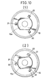
- FIG 10(1) depicts a section of an operative relation between a support shaft and a follower gear before the gear rotates
- FIG 10(2) shows another section similarly to FIG 10(1) after the gear rotate.
- a mirror body 2 supporting a mirror glass is attached to a top end of the stay 1 curved about in a shape of crank, a foundation of the stay 1 is assembled into a bracket case 4 attached to a vehicle body 3.
- the stay 1 is driven by a drive mechanism 5 installed in the bracket case 4.
- the drive mechanism 5 is adapted to transfer power of the drive motor 6 to the support shaft 11 supporting the stay 1 through speed reduction mechanism 7, clutch mechanism 8, drive gear 9, and follower gear 10 so as to rotate the shaft 11.
- the support shaft 11 has a reducing lower end 12a and an enlarged upper end or flanged portion 12.
- the lower end 12a is engaged with the follower gear 10 with a play along a predetermined direction. Rotational force of the follower gear 10 can be transferred to the support shaft 11 after the rotation passes such play zone.
- first engagement means 15 between facing faces of the upper flanged portion 12 and an upper lid 14 of the bracket case 13.
- second engagement means 17 between the follower gear 10 and a lower lid 16 of the bracket case 13.
- the first engagement means 15 consists of a groove 18 formed on a rear side of the flanged portion 12 of the support shaft 11 and a convex portion 18 formed on the upper lid 14 of the bracket case 13. These groove 18 and the convex portion 18 are engaged with each other.
- the second engagement means 17 consists of a slanted concave portion 20 of the follower gear 10, an hole 22 formed on the lower lid 16 of the bracket case 13, and a ball 21 placed in the concave portion 20 and the hole 22.
- the sectional shape of the slanted concave portion 20 is similar to a saucer and the ball 21 can ride or climb along the slanted side wall of the saucer.
- first engagement means 15 is a combination of the groove 18 and the convex portion 19, and
- second engagement means 17 is a combination of the slanted concave portion 20, the ball 21 and hole 22. Always urging and resilient force of a coil spring 23 makes them combined in order to prevent the support shaft 11, or the stay 1 from rotating.
- the clutch mechanism 8 placed at a drive side of the stay housable type motor driven mirror according to the present invention has a pair of convex portion 26 and concave portion 25, respectively formed on an upper face of the drive gear 9 and a lower face of the pressing plate 24.
- the convex portion 26 and concave portion 25 are engaged with each other, so force of the drive motor 6 and the speed reduction gear mechanism 7 is transferred from the pressing plate 24 to the drive gear 9, rotating the follower gear 10 as described above.
- the stay 1 When the mirror body 2 is given some force from the outside, the stay 1 has large load or stress, and rotation force is transferred reversely from the follower gear 10 to the drive gear 9, an engagement of the clutch mechanism 8 is disengaged resisting a force of the spring 27, no load is applied to the speed reduction gear mechanism 7, and the drive motor 6 is prevented from injuring itself such as burning and the like.
- the engagement means 15 and 17 adapted to be effective by spring force supports the support shaft 11 without play or firmly resulting a stable holding of the stay 1 of the motor driven mirror.
- the support shaft 11 for holding and rotating the stay 1 doesn't rotate before these first and second engagement means 15 and 17 are disengaged, it is possible to drive or rotate the stay 1 or support shaft 11 can rotate by a drive mechanism of relatively small in size.
- the drive motor 6, speed reduction gear mechanism 7, and drive gear 9 are longitudinarily arranged, thereby a height H of the bracket case 14 increases, a degree of freedom in designing of the motor driven mirror, when it is attached to the vehicle, decreases, and design allowance of size of construction parts and arrangement of them in an interior of the bracket case 14 is not sufficient.
- the present invention provides a stay housable or storageable type motor driven mirror having a stay, a support shaft, and a drive means, which stay supporting a mirror body at its top end, a foundation of the stay being attached to the support shaft rotatably held in a bracket case, and the support shaft being rotatably driven by the drive means.
- the stay housable type motor driven mirror comprises a drive gear rotatably driven by the drive mechanism, a clutch gear installed on a side of the support shaft so as to idlingly rotate or slide thereon and engaged with the drive gear, a clutch holder inserted in the support shaft at a position beneath of the clutch gear so as to rotate the support shaft when it rotates, a clutch mechanism comprising a pair of convex portion and concave portion, respectively formed on the lower face of the clutch gear and the upper face of the clutch holder so as to engage with each other, and a spring for pressing the clutch gear in order to engage the convex portion and the concave portion of the clutch mechanism with each other, wherein the clutch mechanism is installed at a follower side of a large diameter gear increasing a design allowance of clutch holding torque.
- the stay housable type motor driven mirror of the present invention comprises the drive gear rotatably driven by the drive mechanism or apparatus, a clutch holder fitted onto a lower end portion of the support shaft in order to rotate the support shaft, a clutch gear idlingly fitted on a boss portion of the clutch holder so as to slip and engaged with the drive gear, a clutch mechanism comprising a concave face and a convex face respectively formed on the lower face of the clutch gear and the upper face of the flanged portion of the clutch holder so as to engage with each other, a first spring for pressing the clutch gear so as to make the convex face and concave face of the clutch mechanism engaged with each other, and a second spring for pressing the clutch holder.
- the clutch mechanism is placed at a side of following fear of large diameter and the clutching spring is independently installed, so that a load given to the clutch decreases, wear of the clutch decreases, and a design allowance of clutch holding torque.
- the drive portion of the drive apparatus is transversely arranged, a drive bevel gear is fitted onto the output shaft of the drive portion, and a mid bevel gear mechanism simultaneously engaging with the drive bevel gear and the clutch gear of the follower portion placed at a mid position of the drive portion of the drive apparatus and the follower portion, so that the height of the bracket case is shorten, a design flexibility as to an attachment to the car body increases, and the mid shaft has a bearing portion supporting the output shaft formed therein. Consequently, an interior space of the bracket case increases, a design allowance or flexibility concerning sizes and arrangement layout of the constituent parts or members in the interior space, and the attachment of them simplified.
- a first purpose of the present invention is to provide a stay housable type motor driven mirror having a sufficient design flexibility given to a holding torque of the clutch due to an installation of the clutch mechanism formed at a side of the follower portion, and enabling to be miniatuarized.
- the clutch mechanism is placed at a side of follower of a large diameter gear and the clutching spring is independently installed in order to decrease a load given to the clutch and decrease wear of the clutch. As a result, a design allowance of clutch holding torque increases.
- a mirror body 2 supporting a mirror glass is attached to a top end of the stay 1.
- the foundation of the stay 1 is assembled in the bracket case 4 installed on the car body 3 and driven by a drive mechanism 5 placed within the bracket case 4.
- the drive mechanism 5 of the stay housable type motor driven mirror has a drive motor 31, a speed reduction mechanism 32, and a drive gear 33 mounted on an output shaft 32a of the speed reduction mechanism 32.
- a follower gear 37 is fitted at a lower end portion of the support shaft 36 supporting the stay 1 and rotatably held in the bracket case 4.
- the follower gear 37 consists of a clutch gear 37a idle- rotatably fitted to the support shaft 36 and engaged with the drive gear 33, and a clutch holder 37b engaged with the clutch gear 37a through a clutch mechanism 37c.
- the clutch holder 37b is fitted to the dia-reduced portion 38 at a lower end of the support shaft 36 with a play movement along a predetermined direction.
- the clutch mechanism 37c has a V-shaped protrusion 39b and a V-shaped groove 39a, respectively formed on the lower face of the clutch gear 37a and on the upper face of the clutch holder 37b.
- the clutch mechanism 37c functions when these V-shaped protrusion 39b and V-shaped groove 39a are engaged with each other.
- the clutch mechanism 37c is always urged to engage by means of a coil spring 41 placed between the clutch gear 37a and a spring holder 40 attached to an inner face of the bracket case 4.
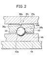
- An engagement means 43 placed on the lower face of the clutch holder 37b consists of a slanted concave portion 43a formed in a base member 4b secured in a lid member 4a placed at a lower interior of the bracket case 4, a ball 42, and a concave portion 43b as shown in FIG 2.
- the coil spring 41 urges the engagement means 43 and also the clutch mechanism 37c.
- the follower gear 37 comprising the clutch mechanism 37c, clutch gear 37a, and clutch holder 37b rotates as a unit, a rotation of the follower gear 37 is transferred to the support shaft 36 to revolve the stay 1 and to move the mirror body 2.
- the stay housable type motor driven mirror comprises the drive gear 33 rotatably driven by the drive mechanism 34, a clutch gear 37a rotatably fitted to the support shaft 36 and engaged with the drive gear 33, a clutch holder 37b fitted to the support shaft 36 beneath the clutch gear 37a so as to rotate the support shaft 36 when it rotates, a clutch mechanism 37c comprising the convex face and concave face, respectively formed on the lower face of the clutch gear 37a and on the upper face of the clutch holder 37b so as to engage with to each other, and a spring 4 for pressing the clutch gear 37a so as to make the convex and the concave faces of the clutch mechanism 37c engaged, wherein the clutch mechanism 37c for giving shock absorbing function when the mirror body 2 is given an outside force is provided at a side of the follower, thereby it is possible to give a design allowance to the clutch holding torque surely making the shock absorbing function effective.
- FIG 3 depicts another or second embodiment of the stay housable type motor driven mirror. Respective corresponding parts or members of the second embodiment shown in FIG 3 have the same reference numerals as that of FIG 1.
- a drive mechanism or apparatus 5 has a drive motor 31, a speed reducing gear mechanism 32, a drive gear 33 provided on an output shaft 32a of the speed reducing gear mechanism 32.
- a follower gear 37 is fitted to a lower end portion of the support shaft 36 rotatably held in the bracket case 4 so as to hold a stay 1.
- the follower gear 37 comprises a clutch holder 37a fitted to a lower end portion of the support shaft 36 so as to rotate the support shaft 36, and a clutch gear 37e engaged with the drive gear 33 and with the flanged portion 37c of the clutch holder 37 through a clutch mechanism 37d.
- the clutch holder 37a is fitted to the dia-reduced portion 38 formed on the lower end of the support shaft 36 with a play along a predetermined rotational direction as shown in FIG 10(1) depicting the conventional stay housable type motor driven mirror.
- the clutch mechanism 37d has a pair of V-shaped groove 39a and V-shaped protrusion 39b, respectively formed on an upper face of the flanged portion 37c of the clutch holder 37a and on a lower face of the clutch gear 37e.
- V-shaped groove 39a and V-shaped protrusion 39b are engaged with each other, a clutching function of the clutch mechanism 37d is done.
- the clutch mechanism 37d is always urged toward a direction of its engagement by means of a first coil spring 41 a interposed between the upper face of the clutch gear 37e and a spring pressor 40 attached to an inner face of the bracket case 4.
- An engagement means 43 is provided on the lower face of the clutch holder 37a.
- the construction of the engagement means 43 is the same as that of the engagement means shown in FIG 2 and it has a combination of the slanted concave portion 43a, ball 42, and concave portion 43b.
- the engagement means 43 is always urged along its engagement direction by a second coil spring 41 inserted between an upper face of a boss portion 37b of the clutch holder 37a and the spring pressor 40.
- the stay housable type motor driven mirror of the present invention has a set of coil springs 41 a and 41 b, so that no influence of the spring effective to the engagement means 43 is applied to the clutch mechanism 37d.
- the stay housable type motor driven mirror of the present invention comprises the drive gear 33 rotatably driven by the drive mechanism or apparatus 34, the clutch holder 37a fitted to the lower end portion of the support shaft 36 so as to rotate the support shaft 36 through its rotation, a clutch gear 37e fitted to the boss portion 37b of the clutch holder 37a in a manner of idling rotation and engaged with the drive gear 33, the clutch mechanism 37d comprising the concave and the convex portions, respectively formed on the lower face of the clutch gear 37e and the upper face of the flanged portion 37c of the clutch holder 37a, the first spring 41 a for pressing the clutch gear 37e so as to make the concave and the convex faces of the clutch mechanism 37e engaged, and the second spring 41 b for pressing the clutch holder 37a.
- urging force of the springs is divided in order to decrease a spring load given to the clutch mechanism 37d giving a shock absorbing effect to the stay 1 when outside force is given to the mirror body 2, wear of the clutching members decreases, and life-time and durability of the motor driven mirror improves.
- clutch mechanism 37d is placed at a side of follower and two springs are installed in the motor driven mirror of the present invention, it is possible to give a design allowance to a clutch holding torque and make the shock absorbing effect sure or reliable. Also, clutching spring to be installed at a side of driving is made unnecessary, and length of the springs to be employed to the motor driven mirror can be shortened by employing to springs, resulting in short height (H size in FIG 2) of the drive portion and minituarization of the whole construction of the mirror.
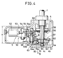
- the drive portion 50 of the drive apparatus 5 of the third embodiment has an output shaft 54 for outputting a power of the drive motor 52 through the speed reduction gear mechanism 53, and a drive bevel gear 55 fitted onto the output shaft 54.
- a follower gear mechanism 57 of a follower portion 56 of the drive apparatus 5 consists of a clutch holder 60 fitted onto a diameter reduced portion 59 placed on the lower portion of a support shaft 58 supporting a stay 1, and a clutch gear 62 fitted onto the clutch holder 60 and engaged with the clutch holder 60 through a clutch mechanism 61.
- a lowest portion of the support shaft 58 is journalled in a journal hole 4c of a base member 4b in a lid body 4a placed under the bracket case 4.
- An engagement means 80 is placed between the base member 4b and the clutch holder 60.
- the clutch mechanism 61 has a pair of concave face 60a and convex face 62a, respectively formed on an upper face of the clutch holder 60 and a lower face of the clutch gear 62 so as to engage with to each other.
- a construction of the engagement means 80 shown in FIG 6 is the same as that of the engagement means shown in FIG 2.
- the engagement means 80 is a combination of a slanted concave portion 70a formed in the base member 4b, a concave portion 81 formed in the clutch holder 60, and a ball 70 placed between the slanted concave portion 70a and the concave portion 81.
- the mid bevel gear mechanism 63 comprises a bevel gear portion 64a engaged with a drive bevel gear 55 of the drive portion 50, a mid bevel gear 65 provided with a spur gear portion 64b engaged with the clutch gear 62 of the follower portion 56, and a mid shaft 66 on which the mid bevel gear 65 is loosely fitted. Both of upper end and lower end of the mid shaft 66 are journalled to the bracket case 4 and the lid body 4a.
- the mid shaft 66 has a bearing portion 67 formed therein to journal or support a front end portion 54a of the output shaft 54 of the drive portion 50.
- the front end portion 54a of the output shaft 54 is inserted into the bearing portion 67 through a bushing 68.
- An E ring 69 supporting the mid bevel gear 65 is attached to the mid shaft 66.
- the drive portion 50 of the drive apparatus 5 is arranged transversely, the drive bevel gear 55 is fitted onto the output shaft 54 of the drive portion 50, the mid bevel gear 65 simultaneously engaged with the drive bevel gear 55 and the clutch gear 63 of the follower portion 56 and the mid shaft 66 fitted loosely on the mid bevel gear 65 are placed at a mid space of the drive portion 50 of the drive apparatus 5 and the follower portion 56, and the mid shaft 66 has the bearing portion 67 supporting the output shaft 54 formed therein, so that a height h of the bracket case 4 decreases and a design freedom or flexibility in attachement of the motor driven mirror to the car body. Further, an interior space of the bracket case 4 increases giving design allowance to the size and arrangement and the like of the constitutional parts of the mirror and simplifying a method and construction of the attachment above.
Landscapes
- Engineering & Computer Science (AREA)
- Multimedia (AREA)
- Mechanical Engineering (AREA)
- Rear-View Mirror Devices That Are Mounted On The Exterior Of The Vehicle (AREA)
Applications Claiming Priority (6)
| Application Number | Priority Date | Filing Date | Title |
|---|---|---|---|
| JP11047590U JPH0469245U (fr) | 1990-10-24 | 1990-10-24 | |
| JP110475/90U | 1990-10-24 | ||
| JP110476/90U | 1990-10-24 | ||
| JP11047690U JPH0469246U (fr) | 1990-10-24 | 1990-10-24 | |
| JP3463691U JPH04122249U (ja) | 1991-04-18 | 1991-04-18 | 電動ステー格納式ミラー |
| JP34636/91U | 1991-04-18 |
Publications (2)
| Publication Number | Publication Date |
|---|---|
| EP0482558A1 true EP0482558A1 (fr) | 1992-04-29 |
| EP0482558B1 EP0482558B1 (fr) | 1996-02-14 |
Family
ID=27288480
Family Applications (1)
| Application Number | Title | Priority Date | Filing Date |
|---|---|---|---|
| EP91117931A Expired - Lifetime EP0482558B1 (fr) | 1990-10-24 | 1991-10-21 | Miroir rétroviseur monté sur un support et actionné par un moteur |
Country Status (3)
| Country | Link |
|---|---|
| US (1) | US5369530A (fr) |
| EP (1) | EP0482558B1 (fr) |
| DE (1) | DE69117130T2 (fr) |
Cited By (5)
| Publication number | Priority date | Publication date | Assignee | Title |
|---|---|---|---|---|
| GB2281543A (en) * | 1993-09-04 | 1995-03-08 | Raydyot Ltd | Mirror mechanisms |
| ES2116850A1 (es) * | 1993-08-14 | 1998-07-16 | Bosch Gmbh Robert | Espejo retrovisor exterior para vehiculos motorizados. |
| WO1999041511A1 (fr) * | 1998-02-17 | 1999-08-19 | Birger Larsson | Support elastique |
| GB2374578A (en) * | 2001-04-17 | 2002-10-23 | Emmanuel Courbon | A parking mechanism for a vehicle mirror |
| ES2574819A1 (es) * | 2014-12-22 | 2016-06-22 | Compañia Levantina De Reductores, S.L. | Sistemas de giro de armazón de espejo retrovisor |
Families Citing this family (18)
| Publication number | Priority date | Publication date | Assignee | Title |
|---|---|---|---|---|
| EP0644084B1 (fr) * | 1993-09-03 | 1998-05-20 | Ichikoh Industries Limited | Système de miroir rétroviseur pour véhicules automobiles |
| US5734517A (en) * | 1993-12-15 | 1998-03-31 | Poong Jeong Ind. Co., Ltd. | Device for regulating motor-driven foldable rear view mirror of automobile |
| US5684646A (en) * | 1995-01-17 | 1997-11-04 | Lowell Engineering Corporation | Exterior mirror with single pivot power fold |
| DE19904777B4 (de) | 1999-02-05 | 2005-12-15 | Mekra Lang Gmbh & Co. Kg | Spiegel, insbesondere Aussenrückspiegel für Kraftfahrzeuge |
| US6257731B1 (en) * | 2000-08-17 | 2001-07-10 | Jaeil Engineering Co., Ltd. | Connections device of actuator for side mirrors of automobile |
| JP3872639B2 (ja) * | 2000-08-31 | 2007-01-24 | 株式会社村上開明堂 | 電動格納式ドアミラー |
| JP4633299B2 (ja) * | 2001-07-12 | 2011-02-16 | 株式会社村上開明堂 | 減速機及び該減速機を備える電動格納式ドアミラー |
| DE10148611B4 (de) | 2001-10-02 | 2005-01-27 | Mekra Lang Gmbh & Co. Kg | Vorrichtung zum schwenkbeweglichen Lagern eines Tragarms für einen Aussenspiegel |
| US7070287B2 (en) * | 2002-04-23 | 2006-07-04 | Magna Donnelly Mirrors North America L.L.C. | Vehicular mirror system with at least one of power-fold and power-extend functionality |
| JP4193785B2 (ja) | 2003-11-19 | 2008-12-10 | 市光工業株式会社 | 車両用電動格納装置の車両への取付方法及びこれに用いる車両用電動格納装置及びこの車両用電動格納装置が取り付けられた車両 |
| JP2006076408A (ja) * | 2004-09-08 | 2006-03-23 | Tokai Rika Co Ltd | 車両用アウタミラー装置の格納機構 |
| JP2008087707A (ja) | 2006-10-04 | 2008-04-17 | Ichikoh Ind Ltd | 車両用アウトサイドミラー装置 |
| JP2008087706A (ja) * | 2006-10-04 | 2008-04-17 | Ichikoh Ind Ltd | 車両用アウトサイドミラー装置 |
| JP4807213B2 (ja) * | 2006-10-04 | 2011-11-02 | 市光工業株式会社 | 車両用アウトサイドミラー装置 |
| CN105164360B (zh) | 2013-04-15 | 2017-04-26 | 卢特龙电子公司 | 具有一体式可存取电池盒的电动式窗上用品 |
| JP6618415B2 (ja) * | 2016-04-08 | 2019-12-11 | 株式会社東海理化電機製作所 | 車両用視認装置 |
| CN105946723A (zh) * | 2016-06-27 | 2016-09-21 | 株洲联诚集团有限责任公司 | 一种机车用齿轮传动后视镜 |
| US12522138B2 (en) * | 2022-04-05 | 2026-01-13 | Magna Mirrors Of America, Inc. | Vehicular exterior mirror assembly with dual/nested coil spring at pivot joint |
Citations (2)
| Publication number | Priority date | Publication date | Assignee | Title |
|---|---|---|---|---|
| EP0314135A1 (fr) * | 1987-10-27 | 1989-05-03 | Ichikoh Industries Limited | Rétroviseur de portière pivotable électriquement |
| EP0367134A1 (fr) * | 1988-11-02 | 1990-05-09 | Dante Siano | Dispositif de commande de la rotation d'un rétroviseur extérieur |
Family Cites Families (8)
| Publication number | Priority date | Publication date | Assignee | Title |
|---|---|---|---|---|
| JPS61191447A (ja) * | 1985-02-19 | 1986-08-26 | Murakami Kaimeidou:Kk | 電動可倒式ドアミラ− |
| JPS61150849A (ja) * | 1984-12-25 | 1986-07-09 | Daihatsu Motor Co Ltd | 車両の後退安全装置 |
| US4832477A (en) * | 1986-09-30 | 1989-05-23 | Aisin Seiki Kabushiki Kaisha | Door mirror assembly for automotive vehicles |
| JPS63173745A (ja) * | 1987-01-13 | 1988-07-18 | Murakami Kaimeidou:Kk | 電動可倒式ドアミラ− |
| JPS641642A (en) * | 1987-06-22 | 1989-01-06 | Honda Motor Co Ltd | Electrically-operated folding door mirror |
| JPH0249638U (fr) * | 1988-09-30 | 1990-04-06 | ||
| JPH0322041A (ja) * | 1989-06-19 | 1991-01-30 | Nec Corp | リアル・タイム・トレーサー |
| US4981349A (en) * | 1989-09-01 | 1991-01-01 | Kabushiki Kaisha Matsuyama Seisakusho | Rearview mirror assembly for automobiles including positioning means with a recess surface extending uniformly horizontally |
-
1991
- 1991-10-17 US US07/774,983 patent/US5369530A/en not_active Expired - Fee Related
- 1991-10-21 DE DE69117130T patent/DE69117130T2/de not_active Expired - Fee Related
- 1991-10-21 EP EP91117931A patent/EP0482558B1/fr not_active Expired - Lifetime
Patent Citations (2)
| Publication number | Priority date | Publication date | Assignee | Title |
|---|---|---|---|---|
| EP0314135A1 (fr) * | 1987-10-27 | 1989-05-03 | Ichikoh Industries Limited | Rétroviseur de portière pivotable électriquement |
| EP0367134A1 (fr) * | 1988-11-02 | 1990-05-09 | Dante Siano | Dispositif de commande de la rotation d'un rétroviseur extérieur |
Non-Patent Citations (2)
| Title |
|---|
| PATENT ABSTRACTS OF JAPAN vol. 10, no. 353 (M-539)(2409) 28 November 1986 & JP-A-61 150 849 ( DAIHATSU MOTOR CO LTD. ) 9 July 1986 * |
| PATENT ABSTRACTS OF JAPAN vol. 14, no. 373 (M-1009)(4316) 13 August 1990 & JP-A-2 136 347 ( DAITO PRESS KOGYO K.K. ) 24 May 1990 * |
Cited By (7)
| Publication number | Priority date | Publication date | Assignee | Title |
|---|---|---|---|---|
| ES2116850A1 (es) * | 1993-08-14 | 1998-07-16 | Bosch Gmbh Robert | Espejo retrovisor exterior para vehiculos motorizados. |
| GB2281543A (en) * | 1993-09-04 | 1995-03-08 | Raydyot Ltd | Mirror mechanisms |
| GB2281543B (en) * | 1993-09-04 | 1996-10-02 | Raydyot Ltd | Mirror mechanisms |
| WO1999041511A1 (fr) * | 1998-02-17 | 1999-08-19 | Birger Larsson | Support elastique |
| GB2374578A (en) * | 2001-04-17 | 2002-10-23 | Emmanuel Courbon | A parking mechanism for a vehicle mirror |
| ES2574819A1 (es) * | 2014-12-22 | 2016-06-22 | Compañia Levantina De Reductores, S.L. | Sistemas de giro de armazón de espejo retrovisor |
| WO2016102724A1 (fr) * | 2014-12-22 | 2016-06-30 | Compañía Levantina De Reductores, S.L. | Système de rotation d'armature de miroir rétroviseur |
Also Published As
| Publication number | Publication date |
|---|---|
| DE69117130D1 (de) | 1996-03-28 |
| DE69117130T2 (de) | 1996-07-04 |
| US5369530A (en) | 1994-11-29 |
| EP0482558B1 (fr) | 1996-02-14 |
Similar Documents
| Publication | Publication Date | Title |
|---|---|---|
| EP0482558A1 (fr) | Miroir rétroviseur monté sur un support et actionné par un moteur | |
| BR9809790A (pt) | Sistema acionado por correia em serpentina para um veìculo automotivo, e, dispositivo para transmitir movimentação de uma correia acionada por um eixo de saìda de um motor para um eixo de um componente auxiliar a ser acionado | |
| FR2449828A1 (fr) | Dispositif amortisseur de torsion, en particulier friction d'embrayage, notamment pour vehicule automobile | |
| US4256375A (en) | Remote controllable motorized rear view mirror | |
| EP0790405A1 (fr) | Démarreur muni d'un dispositif réducteur planétaire | |
| GB1564173A (en) | Vehicle mirrors | |
| FR2387384A1 (fr) | Amortisseur de vibrations de torsion, en particulier pour embrayages de vehicules automobiles | |
| ES2144916A1 (es) | Dispositivo de masas centrifugas con muescas como dentado de un engranaje planaterio. | |
| JPS59151624A (ja) | 車両の動力伝達系における捩り振動吸収装置 | |
| JPH0749081Y2 (ja) | ワンウェイクラッチ | |
| JPH06199186A (ja) | 表示装置の表示部起き上げ機構 | |
| JP3753274B2 (ja) | 遊星歯車減速機構付スタータ | |
| JP2605463Y2 (ja) | ギヤの歯打音防止構造 | |
| JPH0734898U (ja) | 回転テーブル | |
| FR2759965A1 (fr) | Vehicule motorise sur glace | |
| CN216295123U (zh) | 一种惯性可调的动感单车飞轮及动感单车 | |
| JPH017880Y2 (fr) | ||
| EP0682606B1 (fr) | Dispositif de reglage de retroviseur escamotable a moteur pour automobile | |
| CN2326476Y (zh) | 汽车防倒溜装置 | |
| JP2585852Y2 (ja) | 車両用終減速機 | |
| JPS59147137A (ja) | トルク緩衝装置 | |
| JP2569143Y2 (ja) | 差動制限装置 | |
| JPH077997Y2 (ja) | 駆動ユニット | |
| FR2502415A1 (fr) | Moteur electrique dont l'arbre de sortie est porte par les flasques | |
| JPS6321174Y2 (fr) |
Legal Events
| Date | Code | Title | Description |
|---|---|---|---|
| PUAI | Public reference made under article 153(3) epc to a published international application that has entered the european phase |
Free format text: ORIGINAL CODE: 0009012 |
|
| AK | Designated contracting states |
Kind code of ref document: A1 Designated state(s): DE FR GB |
|
| 17P | Request for examination filed |
Effective date: 19920505 |
|
| 17Q | First examination report despatched |
Effective date: 19930715 |
|
| GRAH | Despatch of communication of intention to grant a patent |
Free format text: ORIGINAL CODE: EPIDOS IGRA |
|
| GRAA | (expected) grant |
Free format text: ORIGINAL CODE: 0009210 |
|
| AK | Designated contracting states |
Kind code of ref document: B1 Designated state(s): DE FR GB |
|
| REF | Corresponds to: |
Ref document number: 69117130 Country of ref document: DE Date of ref document: 19960328 |
|
| ET | Fr: translation filed | ||
| PLBE | No opposition filed within time limit |
Free format text: ORIGINAL CODE: 0009261 |
|
| STAA | Information on the status of an ep patent application or granted ep patent |
Free format text: STATUS: NO OPPOSITION FILED WITHIN TIME LIMIT |
|
| 26N | No opposition filed | ||
| PGFP | Annual fee paid to national office [announced via postgrant information from national office to epo] |
Ref country code: FR Payment date: 19991011 Year of fee payment: 9 |
|
| PGFP | Annual fee paid to national office [announced via postgrant information from national office to epo] |
Ref country code: GB Payment date: 19991020 Year of fee payment: 9 |
|
| PGFP | Annual fee paid to national office [announced via postgrant information from national office to epo] |
Ref country code: DE Payment date: 19991022 Year of fee payment: 9 |
|
| PG25 | Lapsed in a contracting state [announced via postgrant information from national office to epo] |
Ref country code: GB Free format text: LAPSE BECAUSE OF NON-PAYMENT OF DUE FEES Effective date: 20001021 |
|
| GBPC | Gb: european patent ceased through non-payment of renewal fee |
Effective date: 20001021 |
|
| PG25 | Lapsed in a contracting state [announced via postgrant information from national office to epo] |
Ref country code: FR Free format text: LAPSE BECAUSE OF NON-PAYMENT OF DUE FEES Effective date: 20010629 |
|
| PG25 | Lapsed in a contracting state [announced via postgrant information from national office to epo] |
Ref country code: DE Free format text: LAPSE BECAUSE OF NON-PAYMENT OF DUE FEES Effective date: 20010703 |
|
| REG | Reference to a national code |
Ref country code: FR Ref legal event code: ST |