EP0482612A1 - Méthode pour appliquer une solution sensible sur une plaque de métal dans la fabrication de tube à rayons cathodiques et appareil de revêtement - Google Patents
Méthode pour appliquer une solution sensible sur une plaque de métal dans la fabrication de tube à rayons cathodiques et appareil de revêtement Download PDFInfo
- Publication number
- EP0482612A1 EP0482612A1 EP91118075A EP91118075A EP0482612A1 EP 0482612 A1 EP0482612 A1 EP 0482612A1 EP 91118075 A EP91118075 A EP 91118075A EP 91118075 A EP91118075 A EP 91118075A EP 0482612 A1 EP0482612 A1 EP 0482612A1
- Authority
- EP
- European Patent Office
- Prior art keywords
- metal plate
- transfer roller
- coating
- sensitizing solution
- iron sheet
- Prior art date
- Legal status (The legal status is an assumption and is not a legal conclusion. Google has not performed a legal analysis and makes no representation as to the accuracy of the status listed.)
- Granted
Links
- 238000000576 coating method Methods 0.000 title claims abstract description 78
- 239000011248 coating agent Substances 0.000 title claims abstract description 75
- 230000001235 sensitizing effect Effects 0.000 title claims abstract description 59
- 239000002184 metal Substances 0.000 title claims abstract description 57
- 229910052751 metal Inorganic materials 0.000 title claims abstract description 57
- 238000000034 method Methods 0.000 title claims description 12
- 238000004519 manufacturing process Methods 0.000 title claims description 7
- 238000012546 transfer Methods 0.000 claims abstract description 65
- 238000005096 rolling process Methods 0.000 claims 3
- XEEYBQQBJWHFJM-UHFFFAOYSA-N Iron Chemical compound [Fe] XEEYBQQBJWHFJM-UHFFFAOYSA-N 0.000 description 228
- 229910052742 iron Inorganic materials 0.000 description 114
- 239000010410 layer Substances 0.000 description 37
- 238000001035 drying Methods 0.000 description 24
- 238000005530 etching Methods 0.000 description 8
- 238000004804 winding Methods 0.000 description 7
- 239000000428 dust Substances 0.000 description 5
- 230000007547 defect Effects 0.000 description 4
- 238000005406 washing Methods 0.000 description 4
- 230000015572 biosynthetic process Effects 0.000 description 3
- 238000010894 electron beam technology Methods 0.000 description 3
- 238000010438 heat treatment Methods 0.000 description 3
- 239000011347 resin Substances 0.000 description 3
- 229920005989 resin Polymers 0.000 description 3
- 238000013459 approach Methods 0.000 description 2
- 239000007921 spray Substances 0.000 description 2
- 238000005507 spraying Methods 0.000 description 2
- PMVSDNDAUGGCCE-TYYBGVCCSA-L Ferrous fumarate Chemical compound [Fe+2].[O-]C(=O)\C=C\C([O-])=O PMVSDNDAUGGCCE-TYYBGVCCSA-L 0.000 description 1
- 230000002411 adverse Effects 0.000 description 1
- 239000011247 coating layer Substances 0.000 description 1
- 238000004891 communication Methods 0.000 description 1
- 238000007796 conventional method Methods 0.000 description 1
- 230000008021 deposition Effects 0.000 description 1
- 230000002093 peripheral effect Effects 0.000 description 1
- 238000000926 separation method Methods 0.000 description 1
- XLYOFNOQVPJJNP-UHFFFAOYSA-N water Substances O XLYOFNOQVPJJNP-UHFFFAOYSA-N 0.000 description 1
Images

Classifications
-
- H—ELECTRICITY
- H01—ELECTRIC ELEMENTS
- H01J—ELECTRIC DISCHARGE TUBES OR DISCHARGE LAMPS
- H01J9/00—Apparatus or processes specially adapted for the manufacture, installation, removal, maintenance of electric discharge tubes, discharge lamps, or parts thereof; Recovery of material from discharge tubes or lamps
- H01J9/02—Manufacture of electrodes or electrode systems
- H01J9/14—Manufacture of electrodes or electrode systems of non-emitting electrodes
-
- B—PERFORMING OPERATIONS; TRANSPORTING
- B05—SPRAYING OR ATOMISING IN GENERAL; APPLYING FLUENT MATERIALS TO SURFACES, IN GENERAL
- B05C—APPARATUS FOR APPLYING FLUENT MATERIALS TO SURFACES, IN GENERAL
- B05C1/00—Apparatus in which liquid or other fluent material is applied to the surface of the work by contact with a member carrying the liquid or other fluent material, e.g. a porous member loaded with a liquid to be applied as a coating
- B05C1/04—Apparatus in which liquid or other fluent material is applied to the surface of the work by contact with a member carrying the liquid or other fluent material, e.g. a porous member loaded with a liquid to be applied as a coating for applying liquid or other fluent material to work of indefinite length
- B05C1/08—Apparatus in which liquid or other fluent material is applied to the surface of the work by contact with a member carrying the liquid or other fluent material, e.g. a porous member loaded with a liquid to be applied as a coating for applying liquid or other fluent material to work of indefinite length using a roller or other rotating member which contacts the work along a generating line
- B05C1/0856—Reverse coating rollers
-
- B—PERFORMING OPERATIONS; TRANSPORTING
- B05—SPRAYING OR ATOMISING IN GENERAL; APPLYING FLUENT MATERIALS TO SURFACES, IN GENERAL
- B05C—APPARATUS FOR APPLYING FLUENT MATERIALS TO SURFACES, IN GENERAL
- B05C1/00—Apparatus in which liquid or other fluent material is applied to the surface of the work by contact with a member carrying the liquid or other fluent material, e.g. a porous member loaded with a liquid to be applied as a coating
- B05C1/04—Apparatus in which liquid or other fluent material is applied to the surface of the work by contact with a member carrying the liquid or other fluent material, e.g. a porous member loaded with a liquid to be applied as a coating for applying liquid or other fluent material to work of indefinite length
- B05C1/08—Apparatus in which liquid or other fluent material is applied to the surface of the work by contact with a member carrying the liquid or other fluent material, e.g. a porous member loaded with a liquid to be applied as a coating for applying liquid or other fluent material to work of indefinite length using a roller or other rotating member which contacts the work along a generating line
- B05C1/0826—Apparatus in which liquid or other fluent material is applied to the surface of the work by contact with a member carrying the liquid or other fluent material, e.g. a porous member loaded with a liquid to be applied as a coating for applying liquid or other fluent material to work of indefinite length using a roller or other rotating member which contacts the work along a generating line the work being a web or sheets
-
- G—PHYSICS
- G03—PHOTOGRAPHY; CINEMATOGRAPHY; ANALOGOUS TECHNIQUES USING WAVES OTHER THAN OPTICAL WAVES; ELECTROGRAPHY; HOLOGRAPHY
- G03F—PHOTOMECHANICAL PRODUCTION OF TEXTURED OR PATTERNED SURFACES, e.g. FOR PRINTING, FOR PROCESSING OF SEMICONDUCTOR DEVICES; MATERIALS THEREFOR; ORIGINALS THEREFOR; APPARATUS SPECIALLY ADAPTED THEREFOR
- G03F7/00—Photomechanical, e.g. photolithographic, production of textured or patterned surfaces, e.g. printing surfaces; Materials therefor, e.g. comprising photoresists; Apparatus specially adapted therefor
- G03F7/16—Coating processes; Apparatus therefor
-
- H—ELECTRICITY
- H01—ELECTRIC ELEMENTS
- H01J—ELECTRIC DISCHARGE TUBES OR DISCHARGE LAMPS
- H01J9/00—Apparatus or processes specially adapted for the manufacture, installation, removal, maintenance of electric discharge tubes, discharge lamps, or parts thereof; Recovery of material from discharge tubes or lamps
- H01J9/02—Manufacture of electrodes or electrode systems
- H01J9/14—Manufacture of electrodes or electrode systems of non-emitting electrodes
- H01J9/142—Manufacture of electrodes or electrode systems of non-emitting electrodes of shadow-masks for colour television tubes
-
- H—ELECTRICITY
- H01—ELECTRIC ELEMENTS
- H01J—ELECTRIC DISCHARGE TUBES OR DISCHARGE LAMPS
- H01J2209/00—Apparatus and processes for manufacture of discharge tubes
- H01J2209/01—Generalised techniques
- H01J2209/012—Coating
- H01J2209/015—Machines therefor
Definitions
- the present invention relates to a method of coating a sensitizing solution onto a metal plate used for manufacturing shadow masks for color cathode ray tubes, and a coating apparatus.
- the coating apparatus comprises, in a sequential order, a supply machine having a roll of elongated metal sheet, i.e., iron sheet, for drawing the sheet from the roll, seam welder, back tension device for imparting a back tension to the running iron sheet, washing tank, drying furnace, coating machine, drying furnace, drive device for running the iron sheet, and winding machine for winding-up the iron sheet.
- the seam welder is used to seam the ends of iron sheets in the case where, when one iron sheet is exhausted on the supply machine, another iron sheet is fed out of another supply machine.
- the coating machine includes a top-opened vessel for storing a sensitizing solution.
- a slit through which the iron sheet passes from the underside of the vessel to the upper-side thereof. Wipers are provided around the slit and slidably and intimately contact with the iron sheet in a liquid-tight fashion, preventing the solution from leaking downward through the slit.
- the iron sheet drawn from the supply machine passes through the lower portion of the seam welder and the back tension device to the washing tank where dust and smudges are washed away from the surfaces of the iron sheet. Then the sheet, after drying up by the drying furnace, is run vertically past the coating machine.
- the iron sheet Upon the passage of the iron sheet through the coating machine, it enters the vessel, via the slit, from below and is moved in the sensitizing solution in the vessel and lifted up from the top-opened end of the vessel with the solution coated on the whole surfaces of the iron sheet.
- the solution-coated iron sheet passes through the drying furnace where the solution dries up by heat on the surfaces of the iron sheet with water evaporated, thus forming resist layers on the surfaces of the iron sheet.
- the resultant iron sheet is run past the iron sheet drive device to the winding machine where it is wound thereon.
- the thickness of the resist layer in the dried state is determined depending upon the concentration and viscosity of the solution stored in the vessel, lift-up speed of the iron sheet being run through the vessel, and heating energy in the drying furnace. That is, the enhanced concentration and viscosity of the sensitizing solution, increased lift-up speed of the iron sheet and increased heating energy at the drying furnace result in an increase in the thickness of the resist layer.
- the concentration of the solution is enhanced so as to increase the thickness of the resist layer, the viscosity of the solution is also increased.
- too high a viscosity results in generating air bubbles in the sensitizing solution and hence in a greater variation in the thickness of the resist layer.
- the coated iron sheet does not sufficiently dry up unless the length of the drying furnace is increased. If the heating energy at the drying furnace is too great, only the surface region of the coated layer on the iron sheet quickly dries up and becomes heavier, but that region of the coated layer which is close to the surface of the iron sheet remains moist, causing a drip or run of the coated solution. Thus, the thickness of the coated layer becomes unstable. This is partly because the coated iron sheet is dried by the drying furnace in a vertical state. The iron sheet vertically lifted up from within the coating machine has its all surfaces coated with the solution and, therefore, has to dry up in the vertical state.
- the conventional method includes a very unstable coating step.
- the "fat edge” phenomenon is not desirable because the iron sheet is irregularly wound up on rollers, etc., at the subsequent step or steps. This is due to the fact that, upon being wound around a winding cylinder, the iron sheet suffers a load only at its side edges and hence has its central area create a gap between its adjacent turns of the iron sheet coil on the cylinder.
- all the iron sheet passes through the sensitizing solution and is coated with the solution also at each side edge.
- the solution deposited on the respective side edge of the iron sheet is originally required, but, once being dried, the dried portion is liable to be peeled from the dried surface of the iron sheet, sometimes causing a fall of dust in the subsequent step or steps.
- an original sensitizing plate is soiled by such dust and hence the deposition of the solution on each side edge of the iron sheet should initially be avoided.
- the iron sheet having the resultant resist layer is transferred to an etching step through an exposure step.
- the iron sheet is etched after an etching solution is sprayed on each resist layer, whereby electron beam passage holes are formed at those positions corresponding to those unexposed resist layer portions of the iron sheet.
- a method of coating a sensitizing solution on an elongated metal plate for use in the manufacture of a shadow mask for color cathode ray tubes comprising the steps of: running the metal plate under predetermined tension in a longitudinal direction of the metal plate; bringing one of surfaces of the running metal plate into contact with a circumferential surface of a transfer roller which is rotated in a direction opposite to that in which the metal plate is run; coating a sensitizing solution on the circumferential surface of the transfer roller with a predetermined thickness; and continuously transfer-coating the coated sensitising solution from the transfer roller onto the one surface of the metal plate.
- a coating apparatus comprising means for running an elongated metal plate under predetermined tension in the longitudinal direction of the iron sheet; a transfer roller having a circumferential surface in contact with one of surfaces of the metal plate; means for coating a sensitizing solution on the circumferential surface of the transfer roller with a predetermined thickness; and means for rotating the transfer roller in a direction opposite to that in which the metal plate is run, so as to continuously transfer the coated sensitizing solution from the transfer roller to the one surface of the metal plate.
- the sensitizing solution is once coated on the transfer roller with a uniform thickness and the coated solution is continuously transfer-coated to the running metal plate under a predetermined tension, enabling it to be uniformly coated on the whole surface of the metal plate without a coating defect.
- the coating of the solution is made on one surface of the plate at a time and it is, therefore, possible to coat the solution separately on each surface of the metal plate and to freely set a thickness with which the solution is coated on each surface of the metal plate.
- Figs. 1 to 5 show a coating apparatus according to an embodiment of the present invention, in which
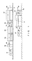
- Fig. 1 is a view schematically showing a coating apparatus for coating a sensitizing solution 2 (see Fig. 3) on an elongated metal plate, e. g., an iron sheet 1 during a process of manufacturing a shadow mask of color cathode ray tubes.
- the coating apparatus comprises a supply machine 31 having a roll of the iron sheet, for drawing the sheet from the roll, seam welder 32, back tension device 33 for imparting tension to the iron sheet, washing tank 34, first drying furnace 35, first coating machine 36 for coating a sensitizing solution on the front surface of the iron sheet 1, second drying furnace 37 and turn roller 38, noting that these components from the supply machine 31 to the turn roller 38 are arranged, for example, on the upper floor of a factory. Further, the coating apparatus comprises a turn roller 39, second coating machine 40 for coating the sensitizing solution to the rear surface of the iron sheet 1, third drying furnace 41, iron sheet drive device 42 for running the iron sheet 1 through the aforementioned components in a direction indicated by arrows in Fig.
- the solution-coated iron sheet passes through the drying furnace in a vertical direction while, according to the embodiment of the present invention, the solution-coated iron sheet passes through the drying furnaces in a horizontal state.
- the solution-coated iron sheet passes through the drying furnaces in a horizontal state.
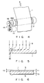
- Figs. 2 to 4 show a detail of the first coating machine 36.
- the first, or the front surface side, coating machine 36 has the same arrangement as that of the second, or the rear surface side, coating machine 40, except that a transfer roller 55 is made in contact with a different surface of the iron sheet 1.
- a transfer roller 55 is made in contact with a different surface of the iron sheet 1.
- the coating machine 36 includes two turn rollers 51, 52 and first and second tension rollers 53, 54.
- the iron sheet 1 running in a direction of an arrow A is wound the rollers 51, 52, 53 and 54 such that predetermined tension is applied to the iron sheet.
- a transfer roller 55 is provided between the first and second tension rollers 53 and 54.
- the transfer roller 55 has its peripheral surface slidably in pressure contact with the front surface of the iron sheet 1.
- the transfer roller 55 is driven by a drive motor 10 through a gear train 12 such that it is relatively rotated at a predetermined speed in a direction B opposite to that in which the iron sheet 1 is run.
- the rollers 51, 52, 53, 54 and 55 are all disposed parallel to one another.
- the transfer roller 55 has a rotation shaft 55a extending parallel with the surfaces of the iron sheet 1 and in a direction perpendicular to the direction A of the run of the iron sheet.
- the transfer roller 55 is made longer than the width of the iron sheet 1, and the circumferential surfaces of both ends of the roller 55 project from each side edge of the iron sheet 1, respectively.
- a linear, sensitizing solution coating nozzle 56 is arranged below the transfer roller 55 and extends parallel with, and opposite to, the transfer roller 55.
- the solution coating nozzle 56 has a body 57 extending parallel with the transfer roller 55, and a resin dam 58 provided on the rear side of the body and extending in a direction parallel with the roller 55.
- the body is formed in a columnar shape having a notch extending in the axis thereof.
- the body 57 is provided at it upper end with a knife edge 57a.
- the knife edge 57a and an upper end surface of the dam 58 are opposite to the circumferential surface of the transfer roller in a parallel relation with a predetermined gap.
- An outlet 59 for the sensitizing solution is opened at a location between the knife edge 57a and the upper end surface of the resin dam 58 and connected to a sensitizing solution supply source, not shown, through a passage 60 defined between the body 57 and the dam.
- the outlet 59 is directed in the direction B in which the transfer roller 55 is rotated.
- the iron sheet 1 is fed out of the supply machine 31 and conveyed past the lower portion of the seam welder 32 and then past the back-tension device 33 to the washing tank 34 where dust and smudges are washed from the surfaces of the iron sheet 1. Then the iron sheet 1 is conveyed to the drying furnace 35 to allow it to dry up, and conveyed past the first coating machine 36 where one surface, for example, the front surface, of the iron sheet 1 is coated with the sensitizing solution 2, the detail of which will be set forth below. The coated iron sheet 1 is conveyed through the drying furnace 37 in a horizontal state.
- the iron sheet is guided downward by the turn roller 38 to the turn roller 39, that is, guided from the upper floor down to the ground floor, with its front surface inverted. Then it is conveyed into the second coating machine 40 where the inverted side, that is, the rear surface, of the iron sheet 1 is coated with the sensitizing solution 2.
- the coated iron sheet 1 after being dried in a horizontal state in the drying furnace 41, is run past the iron sheet drive device 42 to the winding machine 43 where it is wound up.
- the sensitizing solution 2 discharged from the outlet 59 of the coating nozzle 56 is coated onto the circumferential surface of the transfer roller 55 which is rotating in the direction B at a predetermined speed.
- the sensitizing solution 2 is coated on the transfer roller 55 with a thickness corresponding to the gap between the knife edge 57a of the nozzle 56 and the circumferential surface of the transfer roller 55, allowing a solution layer of uniform thickness to be coated on the circumferential surface the transfer roller 55.
- the thickness of the coated solution can freely be set by adjusting the distance of the knife edge 57a relative to the circumferential surface of the transfer roller 55.
- the iron sheet 1 is given predetermined tension by the action of the back tension device 33 and first and second tension rollers 53, 54 and, in that state, moved past these tension rollers 53, 54.
- the iron sheet has one surface pressed in contact with the circumferential surface of the transfer roller 55.
- the solution 2 once being coated on the transfer roller 55 as described above, is continuously transferred and coated on one surface of the sheet while being moved in the direction B prior to an area of contact between the roller 55 and the iron sheet 1.
- the sheet 1 is wrapped around the tension roller 54 while its surface, opposite to that solution-coated surface, is in contact with the tension roller 54 and is conveyed to the drying furnace 37 after it has been changed in its running direction.
- the thickness of the solution to be coated on the transfer roller 55 is set by the knife edge 57a, that is, determined by the gap between the roller 55 and the knife edge 57a of the solution coating nozzle 56. Any excess portion of the solution 2 is flowed past the resin dam 58 and overflowed backward, that is, in the direction opposite to the direction B in which the transfer roller 55 is rotated. Therefore, even if an amount of sensitizing solution 2 supplied to the coating nozzle 56 varies, it does not adversely affect the thickness of the solution 2 to be coated onto the transfer roller 55.
- the transfer roller 55 and coating nozzle 56 can be accurately manufactured by a machine work as finished products, reducing a variation in the thickness of the solution layer, to be transferred to the sheet, to a lesser extent.
- Fig. 5 shows a flow of the solution 2 upon being transferred from the transfer roller 55 to the iron sheet 1.
- the solution 2 which has flown in the direction B of the rotation of the transfer roller 55, is run along the iron sheet 1 in the axial direction of the roller 55 as it approaches the iron sheet 1 and, beyond each side edge of the iron sheet 1, and flows again in the direction B along with the rotation of the roller 55. Since such a flow of the sensitizing solution 2 can be created at each surface side of the iron sheet, the solution is hard to deposit on the side end face of the iron sheet and, at the same time, it does not intrude onto that surface of the iron sheet 1 which is opposite to the surface being coated with the solution 2.
- Fig. 6 is a cross-sectional view showing the thickness of resist layers 3 formed by drying the coated solution on the iron sheet 1, that is, the cross-sectional view taken in the direction perpendicular to the direction A in which the iron sheet 1 is run.
- t2 a x t1
- t1 the thickness of the resist layer 3 at a central area on one surface of the iron sheet 1
- t2 the thickness of the side edge portions of the iron sheet 1
- t3 the thickness of the resist layer 3 at the central area on the other surface of the iron sheet 1
- a becomes about 1.1 to 1.15. That is, the flow of the sensitizing solution 2 as shown in Fig. 5 enables the value a to largely approach 1 compared with a conventional one. This ensures the formation of a resist layer with a substantially uniform thickness throughout the whole iron sheet surface.
- the thickness of the resist layer 3 can be made uniform across the whole width of the iron sheet 1, preventing the iron sheet 1 from being wound in an irregularly shifted relation, at the subsequent step or steps.
- the sensitizing solution 2 is transferred to the iron sheet 1 after being coated once on the transfer roller 55, the solution can be coated under a better condition even if the concentration and viscosity of the solution is made higher than those of the conventional one.
- a sensitizing solution of higher concentration and viscosity it is possible to reduce the formation of a raised portion of the coated solution at each side edge portion of the iron sheet, resulting from the surface tension of the solution. It is thus possible to form a resist layer of more uniform thickness.
- the coating of the sensitizing solution onto each surface of the iron sheet 1 is effected one side at a time with the use of the first coating machine 36 for the front surface and the second coating machine 40 for the rear surface of the iron sheet. It is, therefore, possible to freely vary the thickness of the resist layer 3 on each of the surfaces of the iron sheet 1. That is, it is possible to make the thickness of the resist layer 3 on the front surface of the iron sheet to be different from that the resist layer on the rear surface of the iron sheet. This enhances the freedom with which a flat shadow mask is designed.
- the iron sheet 1 can be so set that, for example, the resist layer 3 is thickened on that surface side where larger holes are formed as electron beam passage holes and is thinned on that surface side of the iron sheet where smaller holes are formed as corresponding holes.
- a defect, such as variation in the thickness of the resist layer is not involved by coating the solution 2 on the iron sheet 1 by the transfer roller 55, not directly by the coating nozzle 56. Further, it is possible to make the concentration and viscosity of the sensitizing solution 2 higher than those of the conventional one, requiring less energy for drying by the drying furnaces 37, 41.
- the thickness of the resist layer 3 can be made about two times as thick as that of the conventional one.
- ticker layer involves no lack or peel of the resist layer even under a higher spraying pressure of the etching solution at the etching step. Due to the flow of the solution 2 as shown in Fig. 5, the solution 2 deposited on each side end surface of the iron sheet 1 can be more prominently saved than that on the conventional apparatus as shown in Fig. 6, resulting in the generation of less dust which would otherwise be unattainable due to the separation of the dried portion of the deposited solution from the iron sheet at the subsequent steps. It is thus possible to suppress the soiling of an original sensitizing plate at an exposure step.
- the sensitizing solution is uniformly coated on the transfer roller in place of using the coating nozzle directly, and continuously transferred and coated on the running iron sheet under a predetermined tension.
- the solution can be uniformly coated throughout the whole length of the iron sheet without involving any defect. It is also possible to freely determine the thickness with which the solution is coated on each surface of the iron sheet.
Landscapes
- Engineering & Computer Science (AREA)
- Manufacturing & Machinery (AREA)
- Physics & Mathematics (AREA)
- General Physics & Mathematics (AREA)
- ing And Chemical Polishing (AREA)
- Application Of Or Painting With Fluid Materials (AREA)
- Coating Apparatus (AREA)
Applications Claiming Priority (2)
| Application Number | Priority Date | Filing Date | Title |
|---|---|---|---|
| JP284968/90 | 1990-10-23 | ||
| JP2284968A JP3034292B2 (ja) | 1990-10-23 | 1990-10-23 | 感光液塗布方法 |
Publications (2)
| Publication Number | Publication Date |
|---|---|
| EP0482612A1 true EP0482612A1 (fr) | 1992-04-29 |
| EP0482612B1 EP0482612B1 (fr) | 1995-09-06 |
Family
ID=17685415
Family Applications (1)
| Application Number | Title | Priority Date | Filing Date |
|---|---|---|---|
| EP91118075A Expired - Lifetime EP0482612B1 (fr) | 1990-10-23 | 1991-10-23 | Méthode pour appliquer une solution sensible sur une plaque de métal dans la fabrication de tube à rayons cathodiques et appareil de revêtement |
Country Status (5)
| Country | Link |
|---|---|
| US (1) | US5230920A (fr) |
| EP (1) | EP0482612B1 (fr) |
| JP (1) | JP3034292B2 (fr) |
| KR (1) | KR950006092B1 (fr) |
| DE (1) | DE69112765T2 (fr) |
Cited By (2)
| Publication number | Priority date | Publication date | Assignee | Title |
|---|---|---|---|---|
| EP0833360A3 (fr) * | 1996-09-30 | 1998-11-04 | Kabushiki Kaisha Toshiba | Procédé de fabrication d'un masque perforé et dispositif pour appliquer une substance résistante à la gravure |
| EP2974798A1 (fr) * | 2014-07-16 | 2016-01-20 | HAUNI Maschinenbau AG | Dispositif d'application d'une bande de colle sur une bande d'enrobage d'un produit en forme de tige de l'industrie de traitement du tabac |
Families Citing this family (6)
| Publication number | Priority date | Publication date | Assignee | Title |
|---|---|---|---|---|
| FI105533B (fi) * | 1992-10-26 | 2000-09-15 | Valmet Paper Machinery Inc | Suihkupäällystyslaitteisto ja -menetelmä |
| US5588998A (en) * | 1992-10-26 | 1996-12-31 | Valmet Corporation | Jet coating apparatus |
| US5747107A (en) * | 1995-10-26 | 1998-05-05 | Minnesota Mining And Manufacturing Company | Method of applying a hot melt coating |
| JPH11251059A (ja) | 1998-02-27 | 1999-09-17 | Sanyo Electric Co Ltd | カラー表示装置 |
| JP3203227B2 (ja) | 1998-02-27 | 2001-08-27 | 三洋電機株式会社 | 表示装置の製造方法 |
| KR100833077B1 (ko) * | 2007-03-21 | 2008-05-27 | 주식회사 포스코 | 코팅롤의 코팅액 비산 방지장치 |
Citations (3)
| Publication number | Priority date | Publication date | Assignee | Title |
|---|---|---|---|---|
| DE2237556A1 (de) * | 1971-08-02 | 1973-02-15 | Ilford Ltd | Beschichtungsverfahren und -vorrichtung |
| US3947609A (en) * | 1972-09-14 | 1976-03-30 | Gte Sylvania Incorporated | Method for coating metallic strips |
| EP0314110A2 (fr) * | 1987-10-28 | 1989-05-03 | Kabushiki Kaisha Toshiba | Procédé de fabrication d'un masque d'ombre |
Family Cites Families (7)
| Publication number | Priority date | Publication date | Assignee | Title |
|---|---|---|---|---|
| US4345543A (en) * | 1978-02-23 | 1982-08-24 | International Business Machines Corporation | Apparatus for forming a coating on a substrate |
| JPS54123151A (en) * | 1978-03-16 | 1979-09-25 | Yokoyama Seisakushiyo Kk | Pipe type docter coater having coating solution reservoir |
| DE2935413C2 (de) * | 1979-09-01 | 1986-02-27 | Küsters, Eduard, 4150 Krefeld | Vorrichtung zum kontinuierlichen Behandeln einer textilen oder ähnlichen Warenbahn mit einem Behandlungsmedium in Schaumform |
| US4442144A (en) * | 1980-11-17 | 1984-04-10 | International Business Machines Corporation | Method for forming a coating on a substrate |
| JPS586533A (ja) * | 1981-07-06 | 1983-01-14 | Tdk Corp | 光記録再生方式 |
| JPS6090065A (ja) * | 1983-10-22 | 1985-05-21 | Konishiroku Photo Ind Co Ltd | 塗布方法及びその装置 |
| US4548840A (en) * | 1984-06-15 | 1985-10-22 | Graham Magnetics Incorporated | High speed coating |
-
1990
- 1990-10-23 JP JP2284968A patent/JP3034292B2/ja not_active Expired - Fee Related
-
1991
- 1991-10-23 US US07/779,736 patent/US5230920A/en not_active Expired - Lifetime
- 1991-10-23 DE DE69112765T patent/DE69112765T2/de not_active Expired - Fee Related
- 1991-10-23 EP EP91118075A patent/EP0482612B1/fr not_active Expired - Lifetime
- 1991-10-25 KR KR1019910018782A patent/KR950006092B1/ko not_active Expired - Fee Related
Patent Citations (3)
| Publication number | Priority date | Publication date | Assignee | Title |
|---|---|---|---|---|
| DE2237556A1 (de) * | 1971-08-02 | 1973-02-15 | Ilford Ltd | Beschichtungsverfahren und -vorrichtung |
| US3947609A (en) * | 1972-09-14 | 1976-03-30 | Gte Sylvania Incorporated | Method for coating metallic strips |
| EP0314110A2 (fr) * | 1987-10-28 | 1989-05-03 | Kabushiki Kaisha Toshiba | Procédé de fabrication d'un masque d'ombre |
Cited By (4)
| Publication number | Priority date | Publication date | Assignee | Title |
|---|---|---|---|---|
| EP0833360A3 (fr) * | 1996-09-30 | 1998-11-04 | Kabushiki Kaisha Toshiba | Procédé de fabrication d'un masque perforé et dispositif pour appliquer une substance résistante à la gravure |
| US6117774A (en) * | 1996-09-30 | 2000-09-12 | Kabushiki Kaisha Toshiba | Method for manufacturing shadow mask and etching-resistant layer-coating apparatus |
| CN1096095C (zh) * | 1996-09-30 | 2002-12-11 | 东芝株式会社 | 荫罩的制造方法及荫罩的制造装置 |
| EP2974798A1 (fr) * | 2014-07-16 | 2016-01-20 | HAUNI Maschinenbau AG | Dispositif d'application d'une bande de colle sur une bande d'enrobage d'un produit en forme de tige de l'industrie de traitement du tabac |
Also Published As
| Publication number | Publication date |
|---|---|
| US5230920A (en) | 1993-07-27 |
| KR950006092B1 (ko) | 1995-06-08 |
| JPH04160725A (ja) | 1992-06-04 |
| EP0482612B1 (fr) | 1995-09-06 |
| DE69112765D1 (de) | 1995-10-12 |
| DE69112765T2 (de) | 1996-02-15 |
| KR920008814A (ko) | 1992-05-28 |
| JP3034292B2 (ja) | 2000-04-17 |
Similar Documents
| Publication | Publication Date | Title |
|---|---|---|
| US5230920A (en) | Method of coating sensitizing solution on metal plate for use in manufacture of color cathode ray tube and coating apparatus | |
| CN113840953B (zh) | 数字化纺织品印刷的方法和设备 | |
| EP0401679B1 (fr) | Procédé et dispositif d'application électrostatique d'une couche de fluide sur un substrat et du séchage de la couche de fluide sur le substrat | |
| KR920003675B1 (ko) | 새도우 마스크 제조방법 | |
| US2710814A (en) | Method for producing light-sensitive coatings on metal webs | |
| US5045358A (en) | Coating head assembly and coating method | |
| US6193897B1 (en) | Shadow mask manufacturing method, shadow mask manufacturing apparatus, and cleaning device used in the method and apparatus | |
| US5688326A (en) | Apparatus for coating elongated material with photoresist | |
| US2791514A (en) | Apparatus and method of coating elongated webs with light-sensitive material | |
| JP3455564B2 (ja) | エナメル線の製造方法及び製造装置 | |
| US3473955A (en) | Coating process | |
| JPS6158559A (ja) | 味付け海苔の製造方法 | |
| JP2002208582A (ja) | 搬送式基板処理装置 | |
| US3947609A (en) | Method for coating metallic strips | |
| TW200533428A (en) | Coating film forming apparatus and coating film forming method | |
| US3875900A (en) | Apparatus and method for coating metallic strips | |
| CN218890728U (zh) | 一种镀锡带材涂油装置 | |
| JP7577087B2 (ja) | プリプレグの製造方法及び製造装置 | |
| JPH026448Y2 (fr) | ||
| JPS5815539B2 (ja) | シヤシンエツチングソウチ | |
| JP2703279B2 (ja) | シャドウマスクの製造方法 | |
| CN111515089A (zh) | 一种ro膜涂布机pva涂布的大辊浸涂装置 | |
| JPH06310031A (ja) | 感光液塗布装置 | |
| JPS6196085A (ja) | シヤドウマスクの製造方法 | |
| JP3814838B2 (ja) | 塗布方法 |
Legal Events
| Date | Code | Title | Description |
|---|---|---|---|
| PUAI | Public reference made under article 153(3) epc to a published international application that has entered the european phase |
Free format text: ORIGINAL CODE: 0009012 |
|
| 17P | Request for examination filed |
Effective date: 19911119 |
|
| AK | Designated contracting states |
Kind code of ref document: A1 Designated state(s): DE FR GB |
|
| 17Q | First examination report despatched |
Effective date: 19930317 |
|
| GRAA | (expected) grant |
Free format text: ORIGINAL CODE: 0009210 |
|
| AK | Designated contracting states |
Kind code of ref document: B1 Designated state(s): DE FR GB |
|
| REF | Corresponds to: |
Ref document number: 69112765 Country of ref document: DE Date of ref document: 19951012 |
|
| ET | Fr: translation filed | ||
| PLBE | No opposition filed within time limit |
Free format text: ORIGINAL CODE: 0009261 |
|
| STAA | Information on the status of an ep patent application or granted ep patent |
Free format text: STATUS: NO OPPOSITION FILED WITHIN TIME LIMIT |
|
| 26N | No opposition filed | ||
| REG | Reference to a national code |
Ref country code: GB Ref legal event code: 746 Effective date: 19980910 |
|
| REG | Reference to a national code |
Ref country code: FR Ref legal event code: D6 |
|
| REG | Reference to a national code |
Ref country code: GB Ref legal event code: IF02 |
|
| PGFP | Annual fee paid to national office [announced via postgrant information from national office to epo] |
Ref country code: GB Payment date: 20061018 Year of fee payment: 16 |
|
| PGFP | Annual fee paid to national office [announced via postgrant information from national office to epo] |
Ref country code: DE Payment date: 20061019 Year of fee payment: 16 |
|
| GBPC | Gb: european patent ceased through non-payment of renewal fee |
Effective date: 20071023 |
|
| PG25 | Lapsed in a contracting state [announced via postgrant information from national office to epo] |
Ref country code: DE Free format text: LAPSE BECAUSE OF NON-PAYMENT OF DUE FEES Effective date: 20080501 |
|
| REG | Reference to a national code |
Ref country code: FR Ref legal event code: ST Effective date: 20080630 |
|
| PGFP | Annual fee paid to national office [announced via postgrant information from national office to epo] |
Ref country code: FR Payment date: 20061010 Year of fee payment: 16 |
|
| PG25 | Lapsed in a contracting state [announced via postgrant information from national office to epo] |
Ref country code: GB Free format text: LAPSE BECAUSE OF NON-PAYMENT OF DUE FEES Effective date: 20071023 |
|
| PG25 | Lapsed in a contracting state [announced via postgrant information from national office to epo] |
Ref country code: FR Free format text: LAPSE BECAUSE OF NON-PAYMENT OF DUE FEES Effective date: 20071031 |