EP0482633A2 - Dispositif d'arrêt - Google Patents
Dispositif d'arrêt Download PDFInfo
- Publication number
- EP0482633A2 EP0482633A2 EP91118146A EP91118146A EP0482633A2 EP 0482633 A2 EP0482633 A2 EP 0482633A2 EP 91118146 A EP91118146 A EP 91118146A EP 91118146 A EP91118146 A EP 91118146A EP 0482633 A2 EP0482633 A2 EP 0482633A2
- Authority
- EP
- European Patent Office
- Prior art keywords
- tube
- rotator
- clamp device
- holder
- passage
- Prior art date
- Legal status (The legal status is an assumption and is not a legal conclusion. Google has not performed a legal analysis and makes no representation as to the accuracy of the status listed.)
- Granted
Links
- 239000012530 fluid Substances 0.000 abstract description 12
- 239000008280 blood Substances 0.000 description 6
- 210000004369 blood Anatomy 0.000 description 6
- 239000003814 drug Substances 0.000 description 4
- XECAHXYUAAWDEL-UHFFFAOYSA-N acrylonitrile butadiene styrene Chemical compound C=CC=C.C=CC#N.C=CC1=CC=CC=C1 XECAHXYUAAWDEL-UHFFFAOYSA-N 0.000 description 3
- 229920000122 acrylonitrile butadiene styrene Polymers 0.000 description 3
- 239000004676 acrylonitrile butadiene styrene Substances 0.000 description 3
- 210000003811 finger Anatomy 0.000 description 3
- 239000004417 polycarbonate Substances 0.000 description 3
- 229930040373 Paraformaldehyde Natural products 0.000 description 2
- 239000004743 Polypropylene Substances 0.000 description 2
- 239000004793 Polystyrene Substances 0.000 description 2
- 229920001893 acrylonitrile styrene Polymers 0.000 description 2
- 239000007788 liquid Substances 0.000 description 2
- 229920006324 polyoxymethylene Polymers 0.000 description 2
- -1 polypropylene Polymers 0.000 description 2
- SCUZVMOVTVSBLE-UHFFFAOYSA-N prop-2-enenitrile;styrene Chemical compound C=CC#N.C=CC1=CC=CC=C1 SCUZVMOVTVSBLE-UHFFFAOYSA-N 0.000 description 2
- 239000000945 filler Substances 0.000 description 1
- 210000003734 kidney Anatomy 0.000 description 1
- 210000004072 lung Anatomy 0.000 description 1
- 239000012994 photoredox catalyst Substances 0.000 description 1
- 229920000515 polycarbonate Polymers 0.000 description 1
- 229920001155 polypropylene Polymers 0.000 description 1
- 229920002223 polystyrene Polymers 0.000 description 1
- 238000007789 sealing Methods 0.000 description 1
- 230000035939 shock Effects 0.000 description 1
- 229920003002 synthetic resin Polymers 0.000 description 1
- 239000000057 synthetic resin Substances 0.000 description 1
- 210000003813 thumb Anatomy 0.000 description 1
- XLYOFNOQVPJJNP-UHFFFAOYSA-N water Substances O XLYOFNOQVPJJNP-UHFFFAOYSA-N 0.000 description 1
Images


Classifications
-
- A—HUMAN NECESSITIES
- A61—MEDICAL OR VETERINARY SCIENCE; HYGIENE
- A61M—DEVICES FOR INTRODUCING MEDIA INTO, OR ONTO, THE BODY; DEVICES FOR TRANSDUCING BODY MEDIA OR FOR TAKING MEDIA FROM THE BODY; DEVICES FOR PRODUCING OR ENDING SLEEP OR STUPOR
- A61M39/00—Tubes, tube connectors, tube couplings, valves, access sites or the like, specially adapted for medical use
- A61M39/22—Valves or arrangement of valves
- A61M39/28—Clamping means for squeezing flexible tubes, e.g. roller clamps
- A61M39/285—Cam clamps, e.g. roller clamps with eccentric axis
Definitions
- the present invention relates to a clamp device which is attached to a soft tube on the way thereof to allow and stop the flow of fluid such as blood and medicine through the tube.
- the soft tube can be applied to liquid medicine transfusion, blood transfusion, and can be employed as the blood circuit of an artificial lung, the blood circuit of an artificial kidney, and the like.
- a rotary cam is incorporated into a holder, a manual operation wheel is attached to the rotary cam and the tube passed through a passage of the holder is gradually pressed and deformed by a large-diameter portion of the rotary cam to stop fluid from flowing through the tube.
- An object of the present invention is to provide a clamp device more compact in size and capable of closing the tube with a smaller force but with a higher reliability.
- Another object of the present invention is to provide a clamp device capable of being positioned nearer the other tool.
- a clamp device comprising a holder having a passage through which a tube is passed in a first direction, a rotator attached to the holder to be rotatable round its rotating axis which extends in a second direction, bearing means formed on the inner face of the holder, supported means formed on the rotator and supported by the bearing means of the holder, tube closing means arranged at the rotator and positioned eccentric to the rotating axis of the rotator, said tube closing means being moved between a first position where the tube is pressed against the inner face of the passage by the tube closing means and a second position where the tube is released from the tube closing means when the rotator is rotated, a rotary operation lever attached to the rotator, and stopper means for stopping the rotator relative to the holder at the first and second positions, wherein the line extending from at least part of the supported means along the rotating axis of the rotator is positioned to cross the passage.
- a guide sleeve by which part of the passage is defined is formed on the holder, the tube in it is connected to a container and it includes a means for fixing the holder to the container.
- a tube closing section of the rotator presses the tube against the inner face of the passage in the holder to close the tube when the rotator is switched from the second or opening position to the first or closing position by the rotary operation lever under a condition that the tube is passed through the passage in the holder.
- the present invention can achieve the following merits in this case.
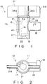
- a clamp device 10 comprises a holder 11 and a rotator 21 incorporated into the holder 11, and it is intended to open and close a resin-made soft tube 1 (shown in Figs. 5A, 5B, 6A and 6B) to allow and stop the flow of fluid such as a liquid medicine or a humor (blood) through the tube 1.
- the holder 11 is shaped substantially like a cylinder, having small- and large-diameter bearing sections 12 and 13 at both ends thereof to hold the rotator 21, a passage 14 at the center thereof to allow the tube 1 to be passed therethrough, and a projected stopper 15 on the inner circumference thereof to tightly stop the rotator 21 at those positions where the tube 1 is opened and closed.
- That inner face of the passage 14 which faces the rotator 21 serves as a flat tube support face 16, and a rectangular window 17 is provided at one open end of the passage 14 while a cylindrical fixing guide sleeve 18 at the other open end thereof.
- One or more rotation stopper projections 19 which are separated from each other in the circumferential direction of the guide sleeve 18 are formed on the front outer circumference of the guide sleeve 18.
- the rotator 21 is provided with a rotary operation lever 21a and small- and large-diameter sections 22 and 23 supported rotatable in the bearing sections 12 and 13 of the holder 11.
- the rotator 21 also has a substantially chord-like tube closing section 24 between the supported sections 22 and 23 which presses the tube 1 passed through the passage 14 of the holder 11 against the tube support face 16 of the passage 14.
- the rotator 21 has tube opening and closing stopper recesses 25a and 25b on the outer circumference of the large-diameter supported section 23 thereof and the tube closing stopper recess 25b separated from the other one 25a in the circumferential surface of the section 23 extends all over the tube closing section 24 of the rotator 21.
- the supported sections 22 and 23 of the rotator 21 are positioned beside the passage 14 of the holder 11 and at that area where the passage 14 is projected.
- the center line passing through these supported sections 22 and 23 of the rotator 21 is positioned this time to cross the passage 14 in the inside of the passage 14.
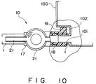
- the fixing guide sleeve 18 and the rotation stopper projections 19 of the holder 11 are used as shown in Fig. 10 in the case of this clamp device 10. While holding the tube 1 in the guide sleeve 18, one end of the tube 1 passed through the passage 14 of the holder 11 and the front end of the guide sleeve 18 are fitted onto an outlet port 101 of a container 100 in which fluid such as blood and medicine is contained. This makes it unnecessary to hold or grip the holder 11 by hand and the rotary operation lever 21a can be thus rotated by fingers of one hand while keeping the holder 11 supported by the fluid container 100. No space is therefore needed around the clamp device 10 to allow the holder 11 to be held by hand, so that the clamp device 10 can be positioned nearer another equipment such as the container 100.
- the tube closing plate 24 of the rotator 21 presses the tube 1 against the inner face 16 of the passage 14 to close the tube 1.
- the clamp device 10 can achieve the following merits 1) and 2) in this case, because the supported sections 22 and 23 of the rotator 21 are positioned beside the passage 14 of the holder 11 and at that area where the passage 14 is projected, as described above.
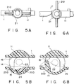
- a clamp device 30 is different from the above-described one 10 in that chord-like tube closing sections 24a and 24b are arranged between the small- and large-diameter supported sections 22 and 23 but at those two positions which are separated from each other by about 180° round the rotating axis of the rotator 21.
- both of the tube closing sections 24a and 24b press the tube 1 in the passage 14 against their corresponding tube support faces 16a and 16b, so that the tube 1 can be more reliably closed by the tube closing plates 24a and 24b at two positions in the axial direction of the tube 1.
- Reference numerals 16c and 16d in Fig. 7 denote stopper faces by which the rotator 21 is stopped at the tube opening position.
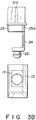
- a clamp device 40 is different from the above-described one 10 in that the tube closing section 24 of a rotator 31 is shaped like a column or rod.
- the tube support faces 16a and 16b are formed on the inner face of the passage 14 of the holder 11 at two positions thereof so as to enable them to face the tube closing column 24 of the rotator 21 when the rotator 21 is rotated left or right from the tube opening position shown in Fig. 8.
- a clamp device 50 is different from the above-described one 10 in that the center line of the supported sections 22 and 23 of the rotator 21 is positioned to cross the passage 14 on the contour line of the passage 14.
- Opening and closing stopper recesses 15a and 15b are formed on the inner circumferential surface of the holder 11 at two positions and the stopper projection 25 on outer circumferential surfaces of the large-diameter supported section 23 and the tube closing section 24 of the rotator 21 at a single position of the rotator 21.
- the rotator 21 is stopped at the opening position where the stopper projection 25 is fitted into the opening stopper recess 15a to make the tube closing section 24 inoperative or at the closing position where the stopper projection 25 is fitted into the closing stopper recess 15b to make the tube closing section 24 operative.
- the holder and the rotator are made of synthetic resin such as PP (polypropylene), AS (acrylonitrile-styrene), PS (polystyrene), ABS (acrylonitrile-butadiene-styrene), POM (polyoxymethylene), and PC (polycarbonate), excellent in rigidity, and particularly PC and ABS, more excellent in toughness and shock resistance, are more suitable.
- a filler may be blended with one of the above-mentioned matters to increase the strength of the holder and the rotator.
- the pressure-tight and sealing capacity of the clamp device 10 was checked under such a condition that a PCV tube having an inner diameter of 6 mm and an outer diameter of 9 mm was set in the clamp device 10 and that air pressure was added to the tube through one end thereof while keeping the other end of the tube immersed in water. No air was leaked through the tube even when the air pressure added was increased to 0.5, 1.0, 1.5, 2.0, 2.5, 3.0 and 3.5 Kgf/cm2. It was thus found that the clamp device 10 had a tube closing capacity which can resist the air pressure of 3.5 Kgf/cm2 added.
Landscapes
- Health & Medical Sciences (AREA)
- Heart & Thoracic Surgery (AREA)
- Pulmonology (AREA)
- Engineering & Computer Science (AREA)
- Anesthesiology (AREA)
- Biomedical Technology (AREA)
- Hematology (AREA)
- Life Sciences & Earth Sciences (AREA)
- Animal Behavior & Ethology (AREA)
- General Health & Medical Sciences (AREA)
- Public Health (AREA)
- Veterinary Medicine (AREA)
- Infusion, Injection, And Reservoir Apparatuses (AREA)
Applications Claiming Priority (2)
| Application Number | Priority Date | Filing Date | Title |
|---|---|---|---|
| JP2285833A JPH0693918B2 (ja) | 1990-10-25 | 1990-10-25 | クレンメ |
| JP285833/90 | 1990-10-25 |
Publications (3)
| Publication Number | Publication Date |
|---|---|
| EP0482633A2 true EP0482633A2 (fr) | 1992-04-29 |
| EP0482633A3 EP0482633A3 (en) | 1992-06-03 |
| EP0482633B1 EP0482633B1 (fr) | 1994-05-25 |
Family
ID=17696672
Family Applications (1)
| Application Number | Title | Priority Date | Filing Date |
|---|---|---|---|
| EP19910118146 Expired - Lifetime EP0482633B1 (fr) | 1990-10-25 | 1991-10-24 | Dispositif d'arrêt |
Country Status (3)
| Country | Link |
|---|---|
| EP (1) | EP0482633B1 (fr) |
| JP (1) | JPH0693918B2 (fr) |
| DE (1) | DE69102120T2 (fr) |
Cited By (4)
| Publication number | Priority date | Publication date | Assignee | Title |
|---|---|---|---|---|
| DE19948233A1 (de) * | 1999-10-07 | 2001-04-12 | Behr Gmbh & Co | Ablaßvorrichtung, insbesondere für Wärmeübertrager von Kraftfahrzeugen |
| EP1504207A4 (fr) * | 2002-05-03 | 2005-10-26 | Acist Medical Sys Inc | Robinet d'arret haute pression stable au rayonnement gamma |
| US8544815B2 (en) | 2006-12-22 | 2013-10-01 | Mondiale Technologies Limited | Flow controller |
| CN112977955A (zh) * | 2021-03-15 | 2021-06-18 | 珠海市维启自动化设备有限公司 | 软管阀、灌粉装置及系统 |
Families Citing this family (1)
| Publication number | Priority date | Publication date | Assignee | Title |
|---|---|---|---|---|
| US7784504B2 (en) * | 2006-03-06 | 2010-08-31 | Baxter International Inc. | Adapters for use with an anesthetic vaporizer |
Family Cites Families (6)
| Publication number | Priority date | Publication date | Assignee | Title |
|---|---|---|---|---|
| US3102710A (en) * | 1959-07-24 | 1963-09-03 | Dresden Anton | Valve having elastomer sleeve |
| US3215394A (en) * | 1962-04-23 | 1965-11-02 | Sherman Lab | Regulable tube clamping device for intravenous injection set |
| US3289999A (en) * | 1963-05-16 | 1966-12-06 | Peter A Konzak | Flow regulator for flexible tubes |
| US3773290A (en) * | 1971-06-01 | 1973-11-20 | Sta Rite Industries | Clamping device for a flexible hose |
| US3920215A (en) * | 1973-02-09 | 1975-11-18 | Dieter W Knauf | Valve |
| US4044989A (en) * | 1974-09-23 | 1977-08-30 | Basel Donald R | Pinch tube valve |
-
1990
- 1990-10-25 JP JP2285833A patent/JPH0693918B2/ja not_active Expired - Lifetime
-
1991
- 1991-10-24 DE DE1991602120 patent/DE69102120T2/de not_active Expired - Fee Related
- 1991-10-24 EP EP19910118146 patent/EP0482633B1/fr not_active Expired - Lifetime
Cited By (6)
| Publication number | Priority date | Publication date | Assignee | Title |
|---|---|---|---|---|
| DE19948233A1 (de) * | 1999-10-07 | 2001-04-12 | Behr Gmbh & Co | Ablaßvorrichtung, insbesondere für Wärmeübertrager von Kraftfahrzeugen |
| EP1504207A4 (fr) * | 2002-05-03 | 2005-10-26 | Acist Medical Sys Inc | Robinet d'arret haute pression stable au rayonnement gamma |
| CN1662762B (zh) * | 2002-05-03 | 2010-05-26 | 阿西斯特医疗系统有限公司 | 一种伽玛稳定的高压旋阀 |
| US8544815B2 (en) | 2006-12-22 | 2013-10-01 | Mondiale Technologies Limited | Flow controller |
| CN112977955A (zh) * | 2021-03-15 | 2021-06-18 | 珠海市维启自动化设备有限公司 | 软管阀、灌粉装置及系统 |
| CN112977955B (zh) * | 2021-03-15 | 2023-02-24 | 珠海市维启自动化设备有限公司 | 软管阀、灌粉装置及系统 |
Also Published As
| Publication number | Publication date |
|---|---|
| JPH0693918B2 (ja) | 1994-11-24 |
| EP0482633A3 (en) | 1992-06-03 |
| DE69102120D1 (de) | 1994-06-30 |
| JPH04161167A (ja) | 1992-06-04 |
| DE69102120T2 (de) | 1994-11-17 |
| EP0482633B1 (fr) | 1994-05-25 |
Similar Documents
| Publication | Publication Date | Title |
|---|---|---|
| US4931044A (en) | Blood collection valve | |
| USRE33219E (en) | Clamp valves | |
| US4794913A (en) | Suction control unit for an endoscope | |
| KR100706741B1 (ko) | 스톱콕 | |
| US9061129B2 (en) | Medical port, blood hose for use in an extracorporeal blood treatment as well as medical treatment appratus | |
| US6695816B2 (en) | Cannula interface | |
| CA2437056C (fr) | Mecanisme d'actionnement pour le deplacement d'un fluide et dispositif de pressurisation | |
| EP3897813B1 (fr) | Valve pour appareil d'urostomie | |
| US5485853A (en) | Apparatus for withdrawing fluid or tissue from a patient's body | |
| US9078611B2 (en) | Clamp and blood collecting device | |
| JP3052287B2 (ja) | ディンプルロック機構を組込んだ試料収集容器用ボール及びソケット蓋 | |
| FI83261B (fi) | Slidventil- och kopplingsaggregat. | |
| CA1190821A (fr) | Dispositif rinceur | |
| JP2001269401A (ja) | コネクタおよびその使用方法 | |
| KR970706036A (ko) | 로킹 덮개를 갖는 반송 세트 커넥터 및 그 사용 방법(Transfer Set Connector with a Locking Lid and a Method of Using the Same) | |
| EP0482633B1 (fr) | Dispositif d'arrêt | |
| JPS6253667A (ja) | 管、特に透析または静脈注射に用いられる管を遮断および切断する方法および装置 | |
| JP2521181B2 (ja) | 線材操作器具 | |
| US20080067465A1 (en) | Liquid coinfusion unit | |
| NO860959L (no) | Kateter for intravaskulaer bruk. | |
| US4576593A (en) | Dosing device for infusion or transfusion of fluids | |
| EP1216663B1 (fr) | Tube de prelevement d'echantillons sous vide | |
| AU778019B2 (en) | Winged injection needle having needle covering means | |
| GB2269884A (en) | A tap | |
| JP3084700B2 (ja) | コネクタ−クランプ |
Legal Events
| Date | Code | Title | Description |
|---|---|---|---|
| PUAI | Public reference made under article 153(3) epc to a published international application that has entered the european phase |
Free format text: ORIGINAL CODE: 0009012 |
|
| PUAL | Search report despatched |
Free format text: ORIGINAL CODE: 0009013 |
|
| 17P | Request for examination filed |
Effective date: 19911024 |
|
| AK | Designated contracting states |
Kind code of ref document: A2 Designated state(s): BE DE FR GB IT |
|
| AK | Designated contracting states |
Kind code of ref document: A3 Designated state(s): BE DE FR GB IT |
|
| 17Q | First examination report despatched |
Effective date: 19930318 |
|
| GRAA | (expected) grant |
Free format text: ORIGINAL CODE: 0009210 |
|
| AK | Designated contracting states |
Kind code of ref document: B1 Designated state(s): BE DE FR GB IT |
|
| PG25 | Lapsed in a contracting state [announced via postgrant information from national office to epo] |
Ref country code: BE Effective date: 19940525 |
|
| ET | Fr: translation filed | ||
| REF | Corresponds to: |
Ref document number: 69102120 Country of ref document: DE Date of ref document: 19940630 |
|
| ITF | It: translation for a ep patent filed | ||
| PLBE | No opposition filed within time limit |
Free format text: ORIGINAL CODE: 0009261 |
|
| STAA | Information on the status of an ep patent application or granted ep patent |
Free format text: STATUS: NO OPPOSITION FILED WITHIN TIME LIMIT |
|
| 26N | No opposition filed | ||
| PG25 | Lapsed in a contracting state [announced via postgrant information from national office to epo] |
Ref country code: GB Effective date: 19951024 |
|
| GBPC | Gb: european patent ceased through non-payment of renewal fee |
Effective date: 19951024 |
|
| PGFP | Annual fee paid to national office [announced via postgrant information from national office to epo] |
Ref country code: DE Payment date: 20061019 Year of fee payment: 16 |
|
| PGFP | Annual fee paid to national office [announced via postgrant information from national office to epo] |
Ref country code: IT Payment date: 20061031 Year of fee payment: 16 |
|
| PG25 | Lapsed in a contracting state [announced via postgrant information from national office to epo] |
Ref country code: DE Free format text: LAPSE BECAUSE OF NON-PAYMENT OF DUE FEES Effective date: 20080501 |
|
| REG | Reference to a national code |
Ref country code: FR Ref legal event code: ST Effective date: 20080630 |
|
| PGFP | Annual fee paid to national office [announced via postgrant information from national office to epo] |
Ref country code: FR Payment date: 20061010 Year of fee payment: 16 |
|
| PG25 | Lapsed in a contracting state [announced via postgrant information from national office to epo] |
Ref country code: FR Free format text: LAPSE BECAUSE OF NON-PAYMENT OF DUE FEES Effective date: 20071031 |
|
| PG25 | Lapsed in a contracting state [announced via postgrant information from national office to epo] |
Ref country code: IT Free format text: LAPSE BECAUSE OF NON-PAYMENT OF DUE FEES Effective date: 20071024 |