EP0482633B1 - Absperrvorrichtung - Google Patents
Absperrvorrichtung Download PDFInfo
- Publication number
- EP0482633B1 EP0482633B1 EP19910118146 EP91118146A EP0482633B1 EP 0482633 B1 EP0482633 B1 EP 0482633B1 EP 19910118146 EP19910118146 EP 19910118146 EP 91118146 A EP91118146 A EP 91118146A EP 0482633 B1 EP0482633 B1 EP 0482633B1
- Authority
- EP
- European Patent Office
- Prior art keywords
- rotator
- tube
- clamp device
- holder
- stopper
- Prior art date
- Legal status (The legal status is an assumption and is not a legal conclusion. Google has not performed a legal analysis and makes no representation as to the accuracy of the status listed.)
- Expired - Lifetime
Links
Images


Classifications
-
- A—HUMAN NECESSITIES
- A61—MEDICAL OR VETERINARY SCIENCE; HYGIENE
- A61M—DEVICES FOR INTRODUCING MEDIA INTO, OR ONTO, THE BODY; DEVICES FOR TRANSDUCING BODY MEDIA OR FOR TAKING MEDIA FROM THE BODY; DEVICES FOR PRODUCING OR ENDING SLEEP OR STUPOR
- A61M39/00—Tubes, tube connectors, tube couplings, valves, access sites or the like, specially adapted for medical use
- A61M39/22—Valves or arrangement of valves
- A61M39/28—Clamping means for squeezing flexible tubes, e.g. roller clamps
- A61M39/285—Cam clamps, e.g. roller clamps with eccentric axis
Definitions
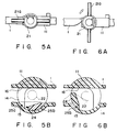
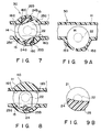
- a rotary operation lever is attached to the rotator, and stopper means are provided for stopping the rotator relative to the holder at the first and second positions.
- stopper means are provided for stopping the rotator relative to the holder at the first and second positions.
- the line extending along the rotating axis of the rotator is positioned to cross the passage.
- a guide sleeve by which part of the passage is defined is formed on the holder, the tube in it is connected to a container and it includes a means for fixing the holder to the container.
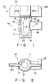
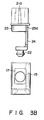
- That inner face of the passage 14 which faces the rotator 21 serves as a flat tube support face 16, and a rectangular window 17 is provided at one open end of the passage 14 while a cylindrical fixing guide sleeve 18 at the other open end thereof.
- One or more rotation stopper projections 19 which are separated from each other in the circumferential direction of the guide sleeve 18 are formed on the front outer circumference of the guide sleeve 18.
Landscapes
- Health & Medical Sciences (AREA)
- Heart & Thoracic Surgery (AREA)
- Pulmonology (AREA)
- Engineering & Computer Science (AREA)
- Anesthesiology (AREA)
- Biomedical Technology (AREA)
- Hematology (AREA)
- Life Sciences & Earth Sciences (AREA)
- Animal Behavior & Ethology (AREA)
- General Health & Medical Sciences (AREA)
- Public Health (AREA)
- Veterinary Medicine (AREA)
- Infusion, Injection, And Reservoir Apparatuses (AREA)
Claims (13)
- Klemmvorrichtung, umfassend- einen Halter (11), der eine Durchführung (14) aufweist, durch die ein Schlauch (1) in einer ersten Richtung durchgeführt wird;- ein Drehteil (21), das so am Halter (11) angebracht ist, daß es um seine Drehachse drehbar ist, die sich in einer zweiten Richtung erstreckt;- eine auf der Innenseite des Halters (11) gebildete Lagereinrichtung (12, 13);- eine Trageinrichtung (22, 23), die auf dem Drehteil (21) gebildet und durch die Lagereinrichtung (12, 13) des Halters (11) getragen ist;- eine Schlauchverschließeinrichtung (24, 24a, 24b), die am Drehteil (21) angeordnet ist und exzentrisch zur Drehachse des Drehteils (21) positioniert ist, wobei die Schlauchverschließeinrichtung (24, 24a, 24b) zwischen einer ersten Position, bei der der Schlauch (1) durch die Schlauchverschließeinrichtung gegen die Innenseite der Durchführung (14) gedrückt ist, und einer zweiten Position bewegt wird, bei der der Schlauch (1) von der Schlauchverschließeinrichtung freigegeben wird, wenn das Drehteil (21) gedreht wird;- einen am Drehteil (21) angebrachten Drehbetätigungshebel (21a); und- eine Anschlageinrichtung (15, 15a, 15b, 25, 25a, 25b, 16c, 16d) zum Anhalten des Drehteils (21) in bezug auf den Halter (11) bei der ersten und zweiten Position;dadurch gekennzeichnet, daß die sich entlang der Drehachse des Drehteils (21) erstreckende Linie so positioniert ist, daß sie die Durchführung (14) kreuzt.
- Klemmvorrichtung nach Anspruch 1, dadurch gekennzeichnet, daß die erste und zweite Richtung im wesentlichen senkrecht zueinander gemacht sind.
- Klemmvorrichtung nach Anspruch 2, dadurch gekennzeichnet, daß die Drehachse des Drehteils (21) so positioniert ist, daß sie die Durchführung (14) kreuzt.
- Klemmvorrichtung nach Anspruch 3, dadurch gekennzeichnet, daß die Drehachse des Drehteils (21) so positioniert ist, daß sie die Mittellinie der Durchführung (14) kreuzt.
- Klemmvorrichtung nach Anspruch 1, dadurch gekennzeichnet, daß die Anschlageinrichtung am Drehteil (21) gebildete erste und zweite Anschlagelemente (25a, 25b) und ein an der Innenseite des Halters (11) gebildetes drittes Anschlagelement (15) aufweist und das dritte Anschlagelement (15) selektiv in Eingriff mit den ersten und zweiten Anschlagelementen gebracht werden kann.
- Klemmvorrichtung nach Anspruch 5, dadurch gekennzeichnet, daß die ersten und zweiten Anschlagelemente Aussparungen (25a, 25b) sind und das dritte Anschlagelement ein Vorsprung (15) ist.
- Klemmvorrichtung nach Anspruch 1, dadurch gekennzeichnet, daß die Anschlageinrichtungen ein am Drehteil (21) gebildetes erstes Anschlagelement (25) und an der Innenseite des Halters (11) gebildete zweite und dritte Anschlagelemente (15a, 15b) umfassen und das erste Anschlagelement selektiv mit den zweiten und dritten Anschlagelementen in Eingriff gebracht werden kann.
- Klemmvorrichtung nach Anspruch 7, dadurch gekennzeichnet, daß das erste Anschlagelement ein Vorsprung (25) ist und die zweiten und dritten Anschlagelemente Aussparungen (15a, 15b) sind.
- Klemmvorrichtung nach Anspruch 1, dadurch gekennzeichnet, daß die Schlauchverschließeinrichtung ein einzelnes Schlauchverschließelement (24) umfaßt.
- Klemmvorrichtung nach Anspruch 1, dadurch gekennzeichnet, daß die Schlauchverschließeinrichtung mehrere Schlauchverschließelemente (24a, 24b) umfaßt.
- Klemmvorrichtung nach Anspruch 1, dadurch gekennzeichnet, daß die Anschlageinrichtungen an der Innenseite des Halters (11) gebildete Elemente (16c, 16d) zum Eingreifen mit der Schlauchverschließeinrichtung (24a, 24b) umfassen, um das Drehteil (21) bei der zweiten Position zu stoppen.
- Klemmvorrichtung nach Anspruch 1, dadurch gekennzeichnet, daß die erste Position mehrfach in bezug auf die zweite Position in beiden Drehrichtungen des Drehteils (21) gebildet ist.
- Klemmvorrichtung nach Anspruch 1, dadurch gekennzeichnet, daß am Halter (11) eine Führungshülse (18) gebildet ist, durch die ein Teil der Durchführung (14) abgegrenzt ist, der Schlauch (1) in der Führungshülse (18) mit einem Behälter (100) verbunden ist und die Führungshülse (18) eine Einrichtung (19) zur Befestigung der Klemmvorrichtung am Behälter (100) umfaßt.
Applications Claiming Priority (2)
| Application Number | Priority Date | Filing Date | Title |
|---|---|---|---|
| JP2285833A JPH0693918B2 (ja) | 1990-10-25 | 1990-10-25 | クレンメ |
| JP285833/90 | 1990-10-25 |
Publications (3)
| Publication Number | Publication Date |
|---|---|
| EP0482633A2 EP0482633A2 (de) | 1992-04-29 |
| EP0482633A3 EP0482633A3 (en) | 1992-06-03 |
| EP0482633B1 true EP0482633B1 (de) | 1994-05-25 |
Family
ID=17696672
Family Applications (1)
| Application Number | Title | Priority Date | Filing Date |
|---|---|---|---|
| EP19910118146 Expired - Lifetime EP0482633B1 (de) | 1990-10-25 | 1991-10-24 | Absperrvorrichtung |
Country Status (3)
| Country | Link |
|---|---|
| EP (1) | EP0482633B1 (de) |
| JP (1) | JPH0693918B2 (de) |
| DE (1) | DE69102120T2 (de) |
Families Citing this family (5)
| Publication number | Priority date | Publication date | Assignee | Title |
|---|---|---|---|---|
| DE19948233A1 (de) * | 1999-10-07 | 2001-04-12 | Behr Gmbh & Co | Ablaßvorrichtung, insbesondere für Wärmeübertrager von Kraftfahrzeugen |
| US6880808B2 (en) * | 2002-05-03 | 2005-04-19 | Acist Medical Systems, Inc. | Gamma-stable high pressure stopcock |
| US7784504B2 (en) * | 2006-03-06 | 2010-08-31 | Baxter International Inc. | Adapters for use with an anesthetic vaporizer |
| WO2008079023A1 (en) | 2006-12-22 | 2008-07-03 | Mondiale Technologies Limited | Flow controller |
| CN112977955B (zh) * | 2021-03-15 | 2023-02-24 | 珠海市维启自动化设备有限公司 | 软管阀、灌粉装置及系统 |
Family Cites Families (6)
| Publication number | Priority date | Publication date | Assignee | Title |
|---|---|---|---|---|
| US3102710A (en) * | 1959-07-24 | 1963-09-03 | Dresden Anton | Valve having elastomer sleeve |
| US3215394A (en) * | 1962-04-23 | 1965-11-02 | Sherman Lab | Regulable tube clamping device for intravenous injection set |
| US3289999A (en) * | 1963-05-16 | 1966-12-06 | Peter A Konzak | Flow regulator for flexible tubes |
| US3773290A (en) * | 1971-06-01 | 1973-11-20 | Sta Rite Industries | Clamping device for a flexible hose |
| US3920215A (en) * | 1973-02-09 | 1975-11-18 | Dieter W Knauf | Valve |
| US4044989A (en) * | 1974-09-23 | 1977-08-30 | Basel Donald R | Pinch tube valve |
-
1990
- 1990-10-25 JP JP2285833A patent/JPH0693918B2/ja not_active Expired - Lifetime
-
1991
- 1991-10-24 DE DE1991602120 patent/DE69102120T2/de not_active Expired - Fee Related
- 1991-10-24 EP EP19910118146 patent/EP0482633B1/de not_active Expired - Lifetime
Also Published As
| Publication number | Publication date |
|---|---|
| JPH0693918B2 (ja) | 1994-11-24 |
| EP0482633A3 (en) | 1992-06-03 |
| DE69102120D1 (de) | 1994-06-30 |
| EP0482633A2 (de) | 1992-04-29 |
| JPH04161167A (ja) | 1992-06-04 |
| DE69102120T2 (de) | 1994-11-17 |
Similar Documents
| Publication | Publication Date | Title |
|---|---|---|
| USRE33219E (en) | Clamp valves | |
| KR100706741B1 (ko) | 스톱콕 | |
| US4931044A (en) | Blood collection valve | |
| US4794913A (en) | Suction control unit for an endoscope | |
| CA2437056C (en) | Actuating mechanism for fluid displacement and pressurizing device | |
| US9061129B2 (en) | Medical port, blood hose for use in an extracorporeal blood treatment as well as medical treatment appratus | |
| CN1829551B (zh) | 医疗用连接系统 | |
| EP2001546B1 (de) | Verschliessbarer luer-stecker | |
| JP3912800B2 (ja) | 医療用チューブコネクタ装置 | |
| US9078611B2 (en) | Clamp and blood collecting device | |
| JP3052287B2 (ja) | ディンプルロック機構を組込んだ試料収集容器用ボール及びソケット蓋 | |
| FI83261B (fi) | Slidventil- och kopplingsaggregat. | |
| CA1280653C (en) | Aseptic irrigation syringe | |
| EP0482633B1 (de) | Absperrvorrichtung | |
| CA1190821A (en) | Flushing device | |
| JP2003033441A (ja) | 三方活栓 | |
| JP2001269401A (ja) | コネクタおよびその使用方法 | |
| CN1717259A (zh) | 用于临时保持注射装置的保护针罩的设备 | |
| KR970706036A (ko) | 로킹 덮개를 갖는 반송 세트 커넥터 및 그 사용 방법(Transfer Set Connector with a Locking Lid and a Method of Using the Same) | |
| JP2521181B2 (ja) | 線材操作器具 | |
| EP1216663B1 (de) | Vakuumprobenröhrchen zur probenentnahme mittels vakuum | |
| GB2269884A (en) | A tap | |
| JP2004506531A (ja) | 仕切られた部分の内部と外部との間を連通するシステム | |
| JP3084700B2 (ja) | コネクタ−クランプ | |
| JPH0628136Y2 (ja) | クランプ |
Legal Events
| Date | Code | Title | Description |
|---|---|---|---|
| PUAI | Public reference made under article 153(3) epc to a published international application that has entered the european phase |
Free format text: ORIGINAL CODE: 0009012 |
|
| PUAL | Search report despatched |
Free format text: ORIGINAL CODE: 0009013 |
|
| 17P | Request for examination filed |
Effective date: 19911024 |
|
| AK | Designated contracting states |
Kind code of ref document: A2 Designated state(s): BE DE FR GB IT |
|
| AK | Designated contracting states |
Kind code of ref document: A3 Designated state(s): BE DE FR GB IT |
|
| 17Q | First examination report despatched |
Effective date: 19930318 |
|
| GRAA | (expected) grant |
Free format text: ORIGINAL CODE: 0009210 |
|
| AK | Designated contracting states |
Kind code of ref document: B1 Designated state(s): BE DE FR GB IT |
|
| PG25 | Lapsed in a contracting state [announced via postgrant information from national office to epo] |
Ref country code: BE Effective date: 19940525 |
|
| ET | Fr: translation filed | ||
| REF | Corresponds to: |
Ref document number: 69102120 Country of ref document: DE Date of ref document: 19940630 |
|
| ITF | It: translation for a ep patent filed | ||
| PLBE | No opposition filed within time limit |
Free format text: ORIGINAL CODE: 0009261 |
|
| STAA | Information on the status of an ep patent application or granted ep patent |
Free format text: STATUS: NO OPPOSITION FILED WITHIN TIME LIMIT |
|
| 26N | No opposition filed | ||
| PG25 | Lapsed in a contracting state [announced via postgrant information from national office to epo] |
Ref country code: GB Effective date: 19951024 |
|
| GBPC | Gb: european patent ceased through non-payment of renewal fee |
Effective date: 19951024 |
|
| PGFP | Annual fee paid to national office [announced via postgrant information from national office to epo] |
Ref country code: DE Payment date: 20061019 Year of fee payment: 16 |
|
| PGFP | Annual fee paid to national office [announced via postgrant information from national office to epo] |
Ref country code: IT Payment date: 20061031 Year of fee payment: 16 |
|
| PG25 | Lapsed in a contracting state [announced via postgrant information from national office to epo] |
Ref country code: DE Free format text: LAPSE BECAUSE OF NON-PAYMENT OF DUE FEES Effective date: 20080501 |
|
| REG | Reference to a national code |
Ref country code: FR Ref legal event code: ST Effective date: 20080630 |
|
| PGFP | Annual fee paid to national office [announced via postgrant information from national office to epo] |
Ref country code: FR Payment date: 20061010 Year of fee payment: 16 |
|
| PG25 | Lapsed in a contracting state [announced via postgrant information from national office to epo] |
Ref country code: FR Free format text: LAPSE BECAUSE OF NON-PAYMENT OF DUE FEES Effective date: 20071031 |
|
| PG25 | Lapsed in a contracting state [announced via postgrant information from national office to epo] |
Ref country code: IT Free format text: LAPSE BECAUSE OF NON-PAYMENT OF DUE FEES Effective date: 20071024 |