EP0482654B1 - Appareil de formation d'images - Google Patents
Appareil de formation d'images Download PDFInfo
- Publication number
- EP0482654B1 EP0482654B1 EP91118186A EP91118186A EP0482654B1 EP 0482654 B1 EP0482654 B1 EP 0482654B1 EP 91118186 A EP91118186 A EP 91118186A EP 91118186 A EP91118186 A EP 91118186A EP 0482654 B1 EP0482654 B1 EP 0482654B1
- Authority
- EP
- European Patent Office
- Prior art keywords
- thin film
- forming apparatus
- image forming
- loop
- conductive
- Prior art date
- Legal status (The legal status is an assumption and is not a legal conclusion. Google has not performed a legal analysis and makes no representation as to the accuracy of the status listed.)
- Expired - Lifetime
Links
- 239000010408 film Substances 0.000 claims description 55
- 239000010410 layer Substances 0.000 claims description 26
- 239000010409 thin film Substances 0.000 claims description 25
- 239000000463 material Substances 0.000 claims description 9
- 239000011347 resin Substances 0.000 claims description 9
- 229920005989 resin Polymers 0.000 claims description 9
- 239000002344 surface layer Substances 0.000 claims description 8
- 239000002245 particle Substances 0.000 claims description 7
- YCKRFDGAMUMZLT-UHFFFAOYSA-N Fluorine atom Chemical compound [F] YCKRFDGAMUMZLT-UHFFFAOYSA-N 0.000 claims description 5
- XUIMIQQOPSSXEZ-UHFFFAOYSA-N Silicon Chemical compound [Si] XUIMIQQOPSSXEZ-UHFFFAOYSA-N 0.000 claims description 5
- 230000005684 electric field Effects 0.000 claims description 5
- 229910052731 fluorine Inorganic materials 0.000 claims description 5
- 239000011737 fluorine Substances 0.000 claims description 5
- 239000004033 plastic Substances 0.000 claims description 5
- 229910052710 silicon Inorganic materials 0.000 claims description 5
- 239000010703 silicon Substances 0.000 claims description 5
- 230000007723 transport mechanism Effects 0.000 claims description 5
- PXHVJJICTQNCMI-UHFFFAOYSA-N Nickel Chemical compound [Ni] PXHVJJICTQNCMI-UHFFFAOYSA-N 0.000 claims description 4
- 239000000919 ceramic Substances 0.000 claims description 3
- RYGMFSIKBFXOCR-UHFFFAOYSA-N Copper Chemical compound [Cu] RYGMFSIKBFXOCR-UHFFFAOYSA-N 0.000 claims description 2
- 239000004952 Polyamide Substances 0.000 claims description 2
- 229910052802 copper Inorganic materials 0.000 claims description 2
- 239000010949 copper Substances 0.000 claims description 2
- 229910052759 nickel Inorganic materials 0.000 claims description 2
- 229920002647 polyamide Polymers 0.000 claims description 2
- 238000007599 discharging Methods 0.000 claims 1
- 108091008695 photoreceptors Proteins 0.000 description 11
- 238000000034 method Methods 0.000 description 10
- 238000010276 construction Methods 0.000 description 8
- 230000008569 process Effects 0.000 description 8
- 239000004020 conductor Substances 0.000 description 4
- 239000000835 fiber Substances 0.000 description 4
- 150000002500 ions Chemical class 0.000 description 4
- 239000002932 luster Substances 0.000 description 4
- 239000002699 waste material Substances 0.000 description 4
- 239000000853 adhesive Substances 0.000 description 3
- 230000001070 adhesive effect Effects 0.000 description 3
- 230000003287 optical effect Effects 0.000 description 3
- 238000004140 cleaning Methods 0.000 description 2
- 230000009467 reduction Effects 0.000 description 2
- 239000003086 colorant Substances 0.000 description 1
- 230000000593 degrading effect Effects 0.000 description 1
- 230000001419 dependent effect Effects 0.000 description 1
- 230000008021 deposition Effects 0.000 description 1
- 238000005516 engineering process Methods 0.000 description 1
- 230000004907 flux Effects 0.000 description 1
- -1 for example Substances 0.000 description 1
- 229910052736 halogen Inorganic materials 0.000 description 1
- 150000002367 halogens Chemical class 0.000 description 1
- 238000010438 heat treatment Methods 0.000 description 1
- 238000003384 imaging method Methods 0.000 description 1
- 238000010884 ion-beam technique Methods 0.000 description 1
- 239000011159 matrix material Substances 0.000 description 1
- 239000002184 metal Substances 0.000 description 1
- 229910052751 metal Inorganic materials 0.000 description 1
- 239000000843 powder Substances 0.000 description 1
Images

Classifications
-
- G—PHYSICS
- G03—PHOTOGRAPHY; CINEMATOGRAPHY; ANALOGOUS TECHNIQUES USING WAVES OTHER THAN OPTICAL WAVES; ELECTROGRAPHY; HOLOGRAPHY
- G03G—ELECTROGRAPHY; ELECTROPHOTOGRAPHY; MAGNETOGRAPHY
- G03G15/00—Apparatus for electrographic processes using a charge pattern
- G03G15/22—Apparatus for electrographic processes using a charge pattern involving the combination of more than one step according to groups G03G13/02 - G03G13/20
- G03G15/32—Apparatus for electrographic processes using a charge pattern involving the combination of more than one step according to groups G03G13/02 - G03G13/20 in which the charge pattern is formed dotwise, e.g. by a thermal head
- G03G15/321—Apparatus for electrographic processes using a charge pattern involving the combination of more than one step according to groups G03G13/02 - G03G13/20 in which the charge pattern is formed dotwise, e.g. by a thermal head by charge transfer onto the recording material in accordance with the image
- G03G15/323—Apparatus for electrographic processes using a charge pattern involving the combination of more than one step according to groups G03G13/02 - G03G13/20 in which the charge pattern is formed dotwise, e.g. by a thermal head by charge transfer onto the recording material in accordance with the image by modulating charged particles through holes or a slit
-
- G—PHYSICS
- G03—PHOTOGRAPHY; CINEMATOGRAPHY; ANALOGOUS TECHNIQUES USING WAVES OTHER THAN OPTICAL WAVES; ELECTROGRAPHY; HOLOGRAPHY
- G03G—ELECTROGRAPHY; ELECTROPHOTOGRAPHY; MAGNETOGRAPHY
- G03G15/00—Apparatus for electrographic processes using a charge pattern
- G03G15/14—Apparatus for electrographic processes using a charge pattern for transferring a pattern to a second base
- G03G15/16—Apparatus for electrographic processes using a charge pattern for transferring a pattern to a second base of a toner pattern, e.g. a powder pattern, e.g. magnetic transfer
- G03G15/1665—Apparatus for electrographic processes using a charge pattern for transferring a pattern to a second base of a toner pattern, e.g. a powder pattern, e.g. magnetic transfer by introducing the second base in the nip formed by the recording member and at least one transfer member, e.g. in combination with bias or heat
- G03G15/167—Apparatus for electrographic processes using a charge pattern for transferring a pattern to a second base of a toner pattern, e.g. a powder pattern, e.g. magnetic transfer by introducing the second base in the nip formed by the recording member and at least one transfer member, e.g. in combination with bias or heat at least one of the recording member or the transfer member being rotatable during the transfer
-
- G—PHYSICS
- G03—PHOTOGRAPHY; CINEMATOGRAPHY; ANALOGOUS TECHNIQUES USING WAVES OTHER THAN OPTICAL WAVES; ELECTROGRAPHY; HOLOGRAPHY
- G03G—ELECTROGRAPHY; ELECTROPHOTOGRAPHY; MAGNETOGRAPHY
- G03G15/00—Apparatus for electrographic processes using a charge pattern
- G03G15/20—Apparatus for electrographic processes using a charge pattern for fixing, e.g. by using heat
- G03G15/2003—Apparatus for electrographic processes using a charge pattern for fixing, e.g. by using heat using heat
- G03G15/2014—Apparatus for electrographic processes using a charge pattern for fixing, e.g. by using heat using heat using contact heat
- G03G15/2064—Apparatus for electrographic processes using a charge pattern for fixing, e.g. by using heat using heat using contact heat combined with pressure
-
- G—PHYSICS
- G03—PHOTOGRAPHY; CINEMATOGRAPHY; ANALOGOUS TECHNIQUES USING WAVES OTHER THAN OPTICAL WAVES; ELECTROGRAPHY; HOLOGRAPHY
- G03G—ELECTROGRAPHY; ELECTROPHOTOGRAPHY; MAGNETOGRAPHY
- G03G15/00—Apparatus for electrographic processes using a charge pattern
- G03G15/22—Apparatus for electrographic processes using a charge pattern involving the combination of more than one step according to groups G03G13/02 - G03G13/20
- G03G15/24—Apparatus for electrographic processes using a charge pattern involving the combination of more than one step according to groups G03G13/02 - G03G13/20 whereby at least two steps are performed simultaneously
-
- G—PHYSICS
- G03—PHOTOGRAPHY; CINEMATOGRAPHY; ANALOGOUS TECHNIQUES USING WAVES OTHER THAN OPTICAL WAVES; ELECTROGRAPHY; HOLOGRAPHY
- G03G—ELECTROGRAPHY; ELECTROPHOTOGRAPHY; MAGNETOGRAPHY
- G03G15/00—Apparatus for electrographic processes using a charge pattern
- G03G15/22—Apparatus for electrographic processes using a charge pattern involving the combination of more than one step according to groups G03G13/02 - G03G13/20
- G03G15/32—Apparatus for electrographic processes using a charge pattern involving the combination of more than one step according to groups G03G13/02 - G03G13/20 in which the charge pattern is formed dotwise, e.g. by a thermal head
- G03G15/321—Apparatus for electrographic processes using a charge pattern involving the combination of more than one step according to groups G03G13/02 - G03G13/20 in which the charge pattern is formed dotwise, e.g. by a thermal head by charge transfer onto the recording material in accordance with the image
-
- G—PHYSICS
- G03—PHOTOGRAPHY; CINEMATOGRAPHY; ANALOGOUS TECHNIQUES USING WAVES OTHER THAN OPTICAL WAVES; ELECTROGRAPHY; HOLOGRAPHY
- G03G—ELECTROGRAPHY; ELECTROPHOTOGRAPHY; MAGNETOGRAPHY
- G03G2215/00—Apparatus for electrophotographic processes
- G03G2215/16—Transferring device, details
- G03G2215/1676—Simultaneous toner image transfer and fixing
- G03G2215/168—Simultaneous toner image transfer and fixing at the first transfer point
- G03G2215/1685—Simultaneous toner image transfer and fixing at the first transfer point using heat
Definitions
- a photoreceptor drum having a photoconductive property is uniformly charged and selectively exposed so that a latent electrostatic image is formed on the photoreceptor.
- the latent electrostatic image is developed with toner particles to form a toner image on the photoreceptor.
- After the toner image is electrostatically transferred from the photoreceptor to a recording medium such as paper.
- the record medium bearing the toner image is passed through a fusing/fixing unit including a pressure roller and a heater roller so that the toner image is fixed on the media.
- a latent electrostatic image is directly formed on a dielectric drum by an ion-current control head known as a latent electrostatic image recording head.
- the latent electrostatic image formed on the dielectric drum is developed to form a toner image on the dielectric drum.
- the toner image is transferred and fixed to a record medium using a pressure roller.
- the image forming apparatus using the photoreceptor drum requires a prescribed length of an optical path from the exposing stage to the drum surface of the photoreceptor. Since the transfer stage and the fixing stage are separately mounted, the transfer unit and the fixing unit must be separately installed. Because of the possibility of degrading the performance of the photoreceptor drum due to heat, it is difficult to install the photoreceptor in close proximity to the fixing unit. For the above two reasons, reduction of the overall size of the image forming apparatus is difficult. Further, 100% transfer efficiency is impossible. Owing to this, toner is inevitably left on the photoreceptor. For removing the residual toner, a cleaner must be provided. For receiving the toner removed by the cleaner, a waste toner receptacle must be provided.
- the present invention has been made in view of the above circumstances and drawbacks. It provides an image forming apparatus which is capable of forming dots all having the same size and shape, and of concurrently performing the transfer and fixing processes without entailing the residual toner after the transfer and the unnatural luster, and does not require the space for securing the prescribed length of the optical path, the cleaner, and the waste toner receptacle, and consequently is small in size.
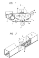
- Fig. 1 is a longitudinal sectional view showing the construction of a printer constructed in accordance with a first embodiment of the present invention.
- a back electrode 3 and a heater 4 are disposed within the loop of the endless film 1.
- the ion-current control head 5, which performs the function of an electrostatic recording head, is located in opposition to the back electrode 3.
- the developing unit 6 is located in opposition to the tension roller 22.
- the pressure roller 7 is opposed to the heater 4.
- the charge removal unit 8 is opposed to the drive roller 21.
- the ion-current control head 5 applies ion beams selectively to the endless film 1 so that a latent electrostatic image is formed on the endless film.
- the latent image is rendered visible with toner particles by the developing unit 6.
- the toner image formed is heated and fused by the heater 4 through the endless film 1.
- the toner image is transferred to a recording medium, such as paper, and the transferred toner image is pressed against the medium to be permanently fixed thereon.
- the discharge unit 8 removes the charge left on the surface of the endless film 1.
- the latent-image bearing film 1 is an endless film composed of two layers, a base layer and a surface layer.
- the base layer is a polyamide film 20 ⁇ m thick, which has properties of a high resiliency and small variation of its geometry under high temperatures. Such properties are required in order to obtain a stable transfer film.
- the surface layer is made of silicon resin or fluorine plastic, which exhibits excellent mold release characteristics when the toner is fused.
- the surface layer is coated with the material to form the surface layer having a thickness of 10 ⁇ m thereover.
- the endless film 1, consisting of the base and surface layers, is capable of retaining ions thereon that are irradiated by the ion-current control head. The portion of the endless film 1 exposed to the ion-current can hold a surface potential of several tens to several hundred volts, which is high enough to develop the latent image in the next stage with respect to the potential of the back electrode 3.
- Fig. 2 is a partially broken perspective view of the ion-current control head 5.
- the ion-current control head 5 includes an ion generator 51 and an ion-current control plate 52 for controlling ion deposition on the endless film 1.
- the ion-current control plate 52 is constructed such that electrodes 54 and 55 are mounted on both sides of an insulating board 53, and holes 56, formed in the insulating board, are arrayed in zig-zag fashion. The number of holes 56 is equal to the number of recording dots.
- the ion-current control plate 52 is arranged parallel to the endless film 1, with the gap therebetween being in the range of 0.3 to 1.5 mm.
- the endless film 1, disposed directly under the ion-current control plate 52, is not curved with respect to the plate. Therefore, the projected images of the fluxes of ions projected through the holes 56 are all the same, irrespective of the locations of the holes.
- a latent electrostatic image recorded on the endless film by the ion-current control head 5 is developed by the developing unit 6.
- the back electrode 3, opposed to the ion-current control head 5, is connected to the tension roller 22, and the 'two electrodes are held at the same potential.
- the developing unit 6 contains toner 61 in the form of a resin powder containing coloring agent. A fixed amount of toner 61 is magnetically or electrostatically attracted to a sleeve 62 of the developing unit.
- the sleeve 62 bearing the toner 61 turns to bring the toner in close proximity to or in contact with the endless film 1.
- An electric field is developed between the endless film 1 and the sleeve 62, to which a preset voltage is applied. Under the electric field, the toner sticks onto the endless film 1, thereby to form a toner image 63.
- the toner image 63 is heated and fused by the heater 4 through the endless film 1, while at the same time pressed against a record media 9 by the pressure roller 7.
- the media 9, together with the endless film, is transferred by the pressure roller 7.
- the fused toner image gets tangled with fibers of the record media 9 and is forced into the spaces among the fibers, generating an adhesive force between the media 9 and the toner image 63.
- the surface layer of the endless film 1 is formed of silicon resin or fluorine plastic which, as described above, has excellent mold release characteristics. Accordingly, the adhesive force between the heated area of the endless film 1 and the fused toner image 63, as considered from the viewpoint of interfacial chemistry, is smaller than the cohesive force of the toner and the adhesive force between the media 9 and the toner image 63.
- the fused toner image 63 is completely transferred from the endless film 1 to the media 9.
- the toner image 63 on the medium 9 which is entangled with the fibers of the media and pushed into the spaces among the fibers, leaves the region where it is thermally influenced by the heat from the heater 4 and the toner temperature drops, the toner image 63 is hardened and fixed to the medium 9. In this way, the toner image 63 is transferred to and fused to the medium 9 all at once.
- the present invention uses the dielectric film 1, which has a high heat resistance, rather than a plain photoreceptive material, as the latent electrostatic image bearing member, allowing the latent electrostatic image bearing member to be directly heated. This realizes a one-stage transferring/fixing operation.
- the medium 9 is transported while being nipped between the pressure roller 7 and the endless film 1. There is no need for using a rotating heated roller containing a bar-like halogen lamp for the heater 4.
- the toner image 63 is heated and fused in such a manner that a ceramic heater 42 supported by a thermal insulating resin 41 is brought into contact with the endless film 1.
- the heat capacity of the heater using the ceramic heater 42 is smaller than that of a heater using the heated roller. Accordingly, the former is superior to the latter in that the warm-up time required to increase temperature of the heater 4 to a preset temperature is short, and the power consumption of the image forming apparatus is reduced.
- Conductive toner provides easy development, but presents a difficulty with respect to its electrostatic transfer to plain paper. For this reason, use of only special paper, e.g., high resistance paper, has conventionally been permitted for the recording medium. In other words, plain paper cannot be used. However, it is noted that in this embodiment, since no electrostatic force is used for the image transfer, plain paper can be used, even if a conductive toner is used.
- the discharge unit 8 is a conductive rubber roller 81 disposed in opposition to the drive roller 21.
- the surface of the drive roller 21 is made of conductive material, similar to the tension roller 22, and is connected to the back electrode 3, while being held at the same potential.
- An AC voltage of 300 to 1000 V in amplitude and 400 to 2000 Hz in frequency superposed on a DC voltage of 50 to 400 V is applied to the conductive rubber roller 81, with the surface potential of the tension roller 22 as a reference potential. With the application of such voltage, the surface potential of the endless film 1 bearing the latent electrostatic image is initialized.
- a conductive rubber roller covered with an insulating layer may be used for the discharge unit.
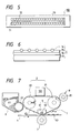
- Fig. 3 is a longitudinal sectional view showing a second embodiment of the present invention.
- the endless film 1 bearing the latent electrostatic image is applied to the rubber belt wound around the rollers.
- the tension roller 22 is disposed at a location opposed to the developing unit 6, and the drive roller 21 is disposed at a location opposed to the discharge unit 8.
- the drive roller 21 is installed at the location where the tension roller 22 is installed in the first embodiment, and vice versa.
- the rubber belt 31 also serving as the back electrode is driven in the direction of an arrow "b" by the drive roller 21.
- the rubber belt 31 is tensioned in the region facing the ion-current control head 5.
- the endless film 1 is transported between the rollers 21 and 22 while being in a close contact with the rubber belt 31, thereby stably maintaining a fixed gap between the ion-current control plate 52 of the head 5 and the endless film 1.
- the conductive rubber belt 31 has two functions, one to transport the endless film 1 and the other to act as the back electrode in the stages of forming the latent image, development, and discharge. Accordingly, there is no need for using a conductive material for the surfaces of the drive roller 21 and the tension roller 22.
- Fig. 4 is a longitudinal sectional view showing a third embodiment of the invention.
- the endless film 1 bearing the latent electrostatic image used in this embodiment is constructed such that an endless film, which has a thickness of 30 ⁇ m and is formed of copper or nickel through an electroprinting process, is coated with silicon resin or fluorine plastic to form a resin layer having a thickness of 20 ⁇ m.
- the latent electrostatic image can be formed without the additional back electrode.
- the 'surfaces of the drive roller 21 and the tension roller 22, which are respectively disposed opposed to the discharge unit and the developing unit, are not necessarily made of conductive material.
- the remaining construction and operation of the present embodiment are substantially the same as those of the first embodiment, and hence a further detailed description will be omitted.
- Figs. 5-7 shows a fourth embodiment of the present invention.
- Fig. 5 shows a plane view of a multistylus-head 100 used in the fourth embodiment.
- main electrodes 71 and auxiliary electrodes 72 are embedded in the structural material 73 having a dielectric character, in such a manner that the main electrodes 71 is aligned at a predetermined interval on a single line and the auxiliary electrodes 72 are arranged at a predetermined interval on two lines.
- the auxiliary electrodes 72 are disposed on the both sides of the main electrodes 71 in parallel at a predetermined interval. All end surfaces of the main electrodes 71, the auxiliary electrodes 72 and the structural material 73 are in the same plane.
- the endless film 1 comprises a dielectric layer 75, an electro-conductive layer 76 and a base layer 77.
- One side surface of the base layer 77 is bonded to one side surface of the electro-conductive layer 76 having a lower resistance character (surface resistance 104 - 1010 ⁇ ), and the other side surface of the electro-conductive layer 76 is bonded to one side surface of the dielectric layer 75.
- Particulates 74 having a dielectric character are adhered to the other side surface of the dielectric layer 75.
- the endless film 1 bearing the latent electrostatic image is mounted in such a manner that the base layer 77 is directed to an inner side, that is, the base layer is brought in contact with the drive roller 21, tension roller 22 and the heater 4.
- the multistylus-head 100 is disposed so as to direct the sectional surface shown in Fig. 5 downward, and the multistylus-head 100 is confronted with a surface of the dielectric layer 75 of the endless film 1 so as to bring the head 100 into contact with the surface of the layer 75.
- the remaining construction and operation of the present embodiment are substantially the same as those of the first embodiment, and hence a further detailed description will be omitted.
- An electrostatic latent image is formed by utilizing a well-known technique, for example, described in "the Voltage Coincident Method, Matrix AND, and so on” (Head Copy Technology, edited by Japan Industrial Technologie Center, 1981).
- a development is conducted by applying a predetermined voltage to the sleeve 62.
- a voltage applying to the sleeve 62 when the base layer 77 has an electro-conductive character is different from a voltage applying to the sleeve 62 when the base layer has a dielectric character.
- the voltage is selected in such a manner that the voltage applying to the sleeve 62 when the base layer 77 has a dielectric character is larger than the voltage applying to the sleeve 62 when the base layer 77 has a conductive character.
- the remaining construction and operation (Transport Mechanism and so on) of the present embodiment are substantially the same as those of the first embodiment, and hence a further detailed description will be omitted.
- the multistylus-head with the same plane control is used, it may be possible to use a multistylus-head with a single plane control or a double plane control (as described by Tokurou Yasuda, A characteristic of a electrostatic recording paper, edited by Electrostatic Academy, 9, 4, page 246-256, 1986).
- the latent electrostatic image forming head is disposed in close proximity to a planar stretch of the endless belt bearing the latent electrostatic image.
- the latent electrostatic image bearing member is formed of an endless film having dielectric and heat-resistance properties, not a photoreceptor. Therefore, the image bearing member may be directly heated, so that transferring and fixing of the toner image to the media can be concurrently performed.
- the transferring and fixing operations are performed at the time when the toner image is heated and fused, neither a transfer unit nor a fixing unit separated by a prescribed distance therebetween need be provided. Further, in the invention, no toner is left on the endless film after the transfer of the latent image. This eliminates the need of a cleaning blade or a waste toner receptacle. In addition, no space for the optical path is needed, leading to a reduction of the overall size of the image forming apparatus.
Landscapes
- Physics & Mathematics (AREA)
- General Physics & Mathematics (AREA)
- Electrophotography Using Other Than Carlson'S Method (AREA)
- Printers Or Recording Devices Using Electromagnetic And Radiation Means (AREA)
- Electrostatic Charge, Transfer And Separation In Electrography (AREA)
- Dry Development In Electrophotography (AREA)
- Fixing For Electrophotography (AREA)
Claims (19)
- Un dispositif de formation d'image comprenant :une boucle sans fin d'un film (1) mince, pour porter une image électrostatique latente, ledit film (1) sans fin étant fait d'un matériau ayant à la fois des propriétés de résistance à la chaleur et diélectriques ;un mécanisme de transport (2), pour entraîner ladite boucle sans fin dudit film (1) mince le long d'un chemin fermé ;une tête (5) d'enregistrement d'image électrostatique latente, disposée à une extension plane de ladite boucle et à l'extérieur de ladite boucle dudit film (1) mince, pour enregistrer une image électrostatique latente sur ledit film (1) mince, où ladite tête d'enregistrement comprend une plaque (52) de commande de courant d'ions plane ayant une pluralité de trous (56) d'éjection d'ions formés en elle, ladite plaque (52) de commande de courant d'ions étant disposée adjacente à un parcours plan dudit film (1) mince ;une électrode (3) arrière, disposée à l'intérieur de ladite boucle dudit film mince, pour opposition à ladite tête (5) d'enregistrement par rapport audit film (1) mince ;une unité (6) de développement, disposée à l'extérieur de ladite boucle dudit film (1) mince, pour développer l'image électrostatique latente sur ledit film (1) sans fin en plaçant des particules de toner (61) à proximité étroite dudit film (1) mince ou en amenant des particules de toner (61) en contact avec ledit film (1) mince ;un dispositif chauffant (4) disposé à l'intérieur de ladite boucle dudit film (1) mince ;une rouleau (7) de pression, opposé audit dispositif chauffant (4) par rapport audit film (1) mince, pour transférer l'image pourvue de toner à un support d'enregistrement (9) et la fixer sur celui-ci ; etune unité (8) de décharge, disposée à l'extérieur de ladite boucle dudit film (1) mince, pour décharger l'image électrostatique latente.
- Le dispositif de formation d'image de la revendication 1, dans lequel ladite électrode (3) arrière est omise, par intégration de sa fonction dans ladite boucle sans fin dudit film (1) mince, comprenant un film (76) conducteur et une couche (75) diélectrique formée sur ledit film (76) conducteur.
- Le dispositif de formation d'image de la revendication 1, dans lequel ledit film mince est formé d'une couche de base d'un film de polyamide et d'une couche de surface faite d'un matériau sélectionné à partir du groupe constitué de résine silicone et de plastique fluoré.
- Le dispositif de formation d'image de la revendication 3, dans lequel ladite couche de base a une épaisseur d'approximativement 20 µm et ladite couche de surface a une épaisseur d'approximativement 10 µm.
- Le dispositif de formation d'image d'une des revendications 1 à 4, dans lequel il y a un interstice, dans une plage de 0,3 à 1,5 mm, entre ladite plaque (52) de commande de courant d'ions et ledit film (1) mince.
- Le dispositif de formation d'image d'une des revendications 1 ou 3 à 5, dans lequel ladite électrode (3) arrière comprend un élément semblable à une plaque, plan, conducteur, disposé à l'intérieur de ladite boucle dudit film (1) mince, à l'opposé de ladite tête d'enregistrement.
- Le dispositif de formation d'image d'une des revendications 1 à 6, dans lequel ledit mécanisme de transport (2) comprend un rouleau (21) d'entraînement et un rouleau (22) de tension.
- Le dispositif de formation d'image de la revendication 7, dans lequel ledit rouleau (22) de tension a une surface extérieure conductrice, à un potentiel égal à un potentiel de ladite électrode (3) arrière.
- Le dispositif de formation d'image d'une des revendications 1 à 8, dans lequel ladite unité (6) de développement comprend un manchon (62) disposé à l'extérieur de ladite boucle dudit film (1) mince, à l'opposé dudit rouleau (22) de tension, ledit manchon (62) étant à un potentiel suffisamment différent dudit potentiel dudit rouleau (22) de tension afin de créer un champ électrique entre ledit manchon (62) conducteur et ledit rouleau (22) de tension, afin de transférer des particules (61) de toner dudit manchon (62) audit film (1) mince.
- Le dispositif de formation d'image d'une des revendications 1 à 9, dans lequel ledit dispositif chauffant (4) comprend un élément chauffant (42) céramique, supporté par une résine (41) isolant thermiquement.
- Le dispositif de formation d'image d'une des revendications 1 à 10, dans lequel ladite unité (8) de décharge comprend un rouleau (81) de caoutchouc conducteur, disposé à l'opposé dudit rouleau (21) d'entraînement.
- Le dispositif de formation d'image de la revendication 11, dans lequel une tension alternative de 100 à 1000 V en amplitude et de 400 à 2000 Hz en fréquence, superposée sur une tension continue de 50 à 400 V en amplitude, est appliquée audit rouleau (81) de caoutchouc conducteur.
- Le dispositif de formation d'image d'une des revendications 1 ou 3 à 12, dans lequel ladite électrode (3) arrière comprend une courroie (31) de caoutchouc conducteur, ladite boucle sans fin dudit film (1) mince étant appliquée au-dessus de ladite courroie (31) de caoutchouc conducteur.
- Le dispositif de formation d'image d'une des revendications 1 à 13, dans lequel ledit mécanisme de transport (2) comprend un rouleau (21) d'entraînement et un rouleau (22) de tension, ledit rouleau (22) de tension étant disposé à l'opposé de ladite unité (8) de décharge et ledit rouleau (21) d'entraînement étant disposé à l'opposé de ladite unité (6) de développement.
- Le dispositif de formation d'image d'une des revendications 1 à 14, dans lequel ladite unité (6) de développement comprend un manchon (62) disposé à l'extérieur de ladite boucle dudit film (1) mince, à l'opposé dudit rouleau (21) d'entraînement, ledit manchon (62) étant à un potentiel suffisamment différent dudit potentiel de ladite courroie (31) de caoutchouc afin de créer un champ électrique entre ledit manchon (62) conducteur et ladite courroie (31) de caoutchouc, afin de transférer des particules (61) de toner dudit manchon (62) audit film (1) mince.
- Le dispositif de formation d'image d'une des revendications 2 à 15, dans lequel ledit film (76) conducteur mince est formé à partir d'un matériau sélectionné à partir du groupe constitué de cuivre et de nickel, et ladite couche (75) diélectrique, formée sur ledit film (76) conducteur, est formée à partir d'un matériau sélectionné à partir du groupe constitué de résine silicone et de plastique fluoré.
- Le dispositif de formation d'image d'une des revendications 2 à 16, dans lequel ledit film (76) conducteur a une épaisseur d'approximativement 30 µm et ladite couche (75) diélectrique a une épaisseur d'approximativement 20 µm.
- Le dispositif de formation d'image d'une des revendications 1 à 17, dans lequel ladite plaque (52) de commande de courant est disposée adjacente à un déplacement plan de ladite boucle dudit film (1) mince et parallèle à ce déplacement plan.
- Le dispositif de formation d'image d'une des revendications 1 à 18, dans lequel ladite unité (6) de développement comprend un manchon (62) disposé à l'extérieur à l'opposé de ladite boucle dudit film (1) mince, à l'opposé dudit rouleau (22) de tension, ledit manchon (62) étant à un potentiel suffisamment différent du potentiel dudit film (1) conducteur afin de créer un champ électrique entre ledit manchon (62) conducteur et ledit film (1) conducteur, afin de transférer des particules (61) de toner dudit manchon (62) audit film (1) mince.
Applications Claiming Priority (2)
| Application Number | Priority Date | Filing Date | Title |
|---|---|---|---|
| JP28623990 | 1990-10-24 | ||
| JP286239/90 | 1990-10-24 |
Publications (3)
| Publication Number | Publication Date |
|---|---|
| EP0482654A2 EP0482654A2 (fr) | 1992-04-29 |
| EP0482654A3 EP0482654A3 (en) | 1993-01-13 |
| EP0482654B1 true EP0482654B1 (fr) | 1996-03-13 |
Family
ID=17701783
Family Applications (1)
| Application Number | Title | Priority Date | Filing Date |
|---|---|---|---|
| EP91118186A Expired - Lifetime EP0482654B1 (fr) | 1990-10-24 | 1991-10-24 | Appareil de formation d'images |
Country Status (5)
| Country | Link |
|---|---|
| US (1) | US5198842A (fr) |
| EP (1) | EP0482654B1 (fr) |
| KR (1) | KR950011879B1 (fr) |
| DE (1) | DE69117865T2 (fr) |
| SG (1) | SG87740A1 (fr) |
Families Citing this family (14)
| Publication number | Priority date | Publication date | Assignee | Title |
|---|---|---|---|---|
| JPH0594101A (ja) * | 1991-10-02 | 1993-04-16 | Hitachi Koki Co Ltd | 電子写真記録装置 |
| JPH05197241A (ja) * | 1992-01-21 | 1993-08-06 | Sharp Corp | 電子写真装置 |
| US5592274A (en) * | 1992-01-31 | 1997-01-07 | Fuji Xerox Co., Ltd. | Electrophotographic apparatus and process for simultaneously transferring and fixing toner image onto transfer paper |
| US5539440A (en) * | 1992-03-30 | 1996-07-23 | Kabushiki Kaisha Toshiba | Image forming apparatus having colorant holding regions and a colorant repelling region |
| JP3283906B2 (ja) * | 1992-06-08 | 2002-05-20 | キヤノン株式会社 | 帯電装置 |
| US5493373A (en) * | 1993-05-03 | 1996-02-20 | Xerox Corporation | Method and apparatus for imaging on a heated intermediate member |
| US5353105A (en) * | 1993-05-03 | 1994-10-04 | Xerox Corporation | Method and apparatus for imaging on a heated intermediate member |
| JP3737562B2 (ja) * | 1996-05-31 | 2006-01-18 | 富士写真フイルム株式会社 | 画像形成装置 |
| US6151048A (en) * | 1996-11-22 | 2000-11-21 | Shiozaki; Eini | Powder-projecting type recording apparatus with transfer medium |
| US6014155A (en) * | 1998-05-01 | 2000-01-11 | Xerox Corporation | Printing machine with a heated imaging member |
| JP2000188177A (ja) * | 1998-12-21 | 2000-07-04 | Fuji Xerox Co Ltd | 電磁誘導加熱装置及びこれを用いた画像記録装置 |
| KR100611991B1 (ko) * | 2004-09-09 | 2006-08-11 | 삼성전자주식회사 | 이온 프린팅 헤드 및 이를 채용한 화상형성장치 |
| KR20080101517A (ko) * | 2007-05-18 | 2008-11-21 | 삼성전자주식회사 | 화상형성장치 및 방법 |
| KR102453483B1 (ko) * | 2021-01-14 | 2022-10-12 | (주)세아메카닉스 | 다이캐스팅 주조기용 진공블럭 검사장치 |
Family Cites Families (14)
| Publication number | Priority date | Publication date | Assignee | Title |
|---|---|---|---|---|
| JPS4923213B1 (fr) * | 1969-08-01 | 1974-06-14 | ||
| US4357618A (en) * | 1978-10-16 | 1982-11-02 | Algographic Associates | Electrostatic imaging apparatus |
| US4365549A (en) * | 1978-12-14 | 1982-12-28 | Dennison Manufacturing Company | Electrostatic transfer printing |
| US4363070A (en) * | 1980-09-02 | 1982-12-07 | Polaroid Corporation | Neutralization of electrostatic charges |
| US4535345A (en) * | 1983-06-20 | 1985-08-13 | Xerox Corporation | Ion projection printer with extended back electrode |
| US4745030A (en) * | 1984-10-15 | 1988-05-17 | Canon Kabushiki Kaisha | Electrostatic recording device |
| US4799070A (en) * | 1986-03-26 | 1989-01-17 | Olympus Optical Co., Ltd. | Ion flow electrostatic recording process and apparatus |
| US4879194A (en) * | 1988-05-02 | 1989-11-07 | Xerox Corporation | Tri-level, highlight color imaging using ionography |
| JPH0717073B2 (ja) * | 1988-08-04 | 1995-03-01 | 富士ゼロックス株式会社 | 静電潜像形成装置 |
| JPH0823723B2 (ja) * | 1989-03-28 | 1996-03-06 | キヤノン株式会社 | 定着装置 |
| US4891656A (en) * | 1988-12-14 | 1990-01-02 | Delphax Systems | Print cartridge with non-divergent electrostatic field |
| EP0380130A3 (fr) * | 1989-01-27 | 1991-09-18 | Oki Electric Industry Co., Ltd. | Appareil électrophotographique utilisant un film pour porter une image d'agent de contraste |
| US5063397A (en) * | 1990-05-25 | 1991-11-05 | Xerox Corporation | Variable-thickness imaging members |
| US5196870A (en) * | 1990-07-10 | 1993-03-23 | Oki Electric Industry Co., Ltd. | Electrophotographic printer |
-
1991
- 1991-10-18 US US07/779,242 patent/US5198842A/en not_active Expired - Lifetime
- 1991-10-24 EP EP91118186A patent/EP0482654B1/fr not_active Expired - Lifetime
- 1991-10-24 SG SG9608795A patent/SG87740A1/en unknown
- 1991-10-24 KR KR1019910018720A patent/KR950011879B1/ko not_active Expired - Fee Related
- 1991-10-24 DE DE69117865T patent/DE69117865T2/de not_active Expired - Fee Related
Also Published As
| Publication number | Publication date |
|---|---|
| DE69117865D1 (de) | 1996-04-18 |
| EP0482654A2 (fr) | 1992-04-29 |
| EP0482654A3 (en) | 1993-01-13 |
| KR950011879B1 (ko) | 1995-10-11 |
| KR920008560A (ko) | 1992-05-28 |
| US5198842A (en) | 1993-03-30 |
| DE69117865T2 (de) | 1996-08-14 |
| SG87740A1 (en) | 2002-04-16 |
Similar Documents
| Publication | Publication Date | Title |
|---|---|---|
| US5881349A (en) | Image induction heating apparatus | |
| EP0482654B1 (fr) | Appareil de formation d'images | |
| JPS64698B2 (fr) | ||
| US5724637A (en) | Fixing roller having low resistance layer and fixing apparatus using same | |
| EP0380132B1 (fr) | Méthode et appareil de formation d'images en couleurs | |
| EP0860752B1 (fr) | Appareil de formation d'images utilisant un appareil de fixage | |
| US5708950A (en) | Transfuser | |
| JPH05134505A (ja) | 焦電気式直接マーキング方法および装置 | |
| US7254360B2 (en) | Image fixing apparatus, and, image forming apparatus having the same, and image forming process | |
| US4636815A (en) | Electrostatic recording apparatus | |
| JP3347537B2 (ja) | 像加熱装置 | |
| JPH0944020A (ja) | 定着器及び定着器構造体を構成する方法 | |
| JPH07210020A (ja) | 加熱加圧フューザ及び定着方法 | |
| JP2728579B2 (ja) | 電子写真装置 | |
| KR970003377B1 (ko) | 기록장치 | |
| JP3450585B2 (ja) | 像加熱装置 | |
| JP2002091171A (ja) | 画像形成装置及び画像転写方法 | |
| JPH07225511A (ja) | 画像記録装置 | |
| JP2003208051A (ja) | 小型の長ニップ融着装置及び静電写真複製装置 | |
| JP2803632B2 (ja) | 画像記録装置 | |
| JP2001092296A (ja) | 像加熱装置及び画像形成装置 | |
| JP2003107940A (ja) | 加熱定着装置及びそれを用いた画像形成装置 | |
| JPH03144676A (ja) | 画像加熱定着装置 | |
| KR20060110098A (ko) | 정착벨트를 포함한 정착기 | |
| JPH056059A (ja) | 画像形成装置 |
Legal Events
| Date | Code | Title | Description |
|---|---|---|---|
| PUAI | Public reference made under article 153(3) epc to a published international application that has entered the european phase |
Free format text: ORIGINAL CODE: 0009012 |
|
| AK | Designated contracting states |
Kind code of ref document: A2 Designated state(s): DE FR GB IT NL |
|
| PUAL | Search report despatched |
Free format text: ORIGINAL CODE: 0009013 |
|
| AK | Designated contracting states |
Kind code of ref document: A3 Designated state(s): DE FR GB IT NL |
|
| 17P | Request for examination filed |
Effective date: 19930430 |
|
| 17Q | First examination report despatched |
Effective date: 19940504 |
|
| GRAH | Despatch of communication of intention to grant a patent |
Free format text: ORIGINAL CODE: EPIDOS IGRA |
|
| GRAA | (expected) grant |
Free format text: ORIGINAL CODE: 0009210 |
|
| AK | Designated contracting states |
Kind code of ref document: B1 Designated state(s): DE FR GB IT NL |
|
| ITF | It: translation for a ep patent filed | ||
| REF | Corresponds to: |
Ref document number: 69117865 Country of ref document: DE Date of ref document: 19960418 |
|
| ET | Fr: translation filed | ||
| PLBE | No opposition filed within time limit |
Free format text: ORIGINAL CODE: 0009261 |
|
| STAA | Information on the status of an ep patent application or granted ep patent |
Free format text: STATUS: NO OPPOSITION FILED WITHIN TIME LIMIT |
|
| 26N | No opposition filed | ||
| REG | Reference to a national code |
Ref country code: GB Ref legal event code: IF02 |
|
| PGFP | Annual fee paid to national office [announced via postgrant information from national office to epo] |
Ref country code: NL Payment date: 20071015 Year of fee payment: 17 Ref country code: DE Payment date: 20071018 Year of fee payment: 17 |
|
| PGFP | Annual fee paid to national office [announced via postgrant information from national office to epo] |
Ref country code: IT Payment date: 20071027 Year of fee payment: 17 |
|
| PGFP | Annual fee paid to national office [announced via postgrant information from national office to epo] |
Ref country code: GB Payment date: 20071024 Year of fee payment: 17 Ref country code: FR Payment date: 20071009 Year of fee payment: 17 |
|
| GBPC | Gb: european patent ceased through non-payment of renewal fee |
Effective date: 20081024 |
|
| NLV4 | Nl: lapsed or anulled due to non-payment of the annual fee |
Effective date: 20090501 |
|
| REG | Reference to a national code |
Ref country code: FR Ref legal event code: ST Effective date: 20090630 |
|
| PG25 | Lapsed in a contracting state [announced via postgrant information from national office to epo] |
Ref country code: NL Free format text: LAPSE BECAUSE OF NON-PAYMENT OF DUE FEES Effective date: 20090501 |
|
| PG25 | Lapsed in a contracting state [announced via postgrant information from national office to epo] |
Ref country code: IT Free format text: LAPSE BECAUSE OF NON-PAYMENT OF DUE FEES Effective date: 20081024 Ref country code: DE Free format text: LAPSE BECAUSE OF NON-PAYMENT OF DUE FEES Effective date: 20090501 |
|
| PG25 | Lapsed in a contracting state [announced via postgrant information from national office to epo] |
Ref country code: FR Free format text: LAPSE BECAUSE OF NON-PAYMENT OF DUE FEES Effective date: 20081031 |
|
| PG25 | Lapsed in a contracting state [announced via postgrant information from national office to epo] |
Ref country code: GB Free format text: LAPSE BECAUSE OF NON-PAYMENT OF DUE FEES Effective date: 20081024 |