EP0482680A1 - Programmierbares Beleuchtungssystem - Google Patents
Programmierbares Beleuchtungssystem Download PDFInfo
- Publication number
- EP0482680A1 EP0482680A1 EP91200419A EP91200419A EP0482680A1 EP 0482680 A1 EP0482680 A1 EP 0482680A1 EP 91200419 A EP91200419 A EP 91200419A EP 91200419 A EP91200419 A EP 91200419A EP 0482680 A1 EP0482680 A1 EP 0482680A1
- Authority
- EP
- European Patent Office
- Prior art keywords
- illumination
- light output
- programming
- output level
- units
- Prior art date
- Legal status (The legal status is an assumption and is not a legal conclusion. Google has not performed a legal analysis and makes no representation as to the accuracy of the status listed.)
- Withdrawn
Links
Images

Classifications
-
- G—PHYSICS
- G05—CONTROLLING; REGULATING
- G05B—CONTROL OR REGULATING SYSTEMS IN GENERAL; FUNCTIONAL ELEMENTS OF SUCH SYSTEMS; MONITORING OR TESTING ARRANGEMENTS FOR SUCH SYSTEMS OR ELEMENTS
- G05B19/00—Program-control systems
- G05B19/02—Program-control systems electric
- G05B19/04—Program control other than numerical control, i.e. in sequence controllers or logic controllers
- G05B19/042—Program control other than numerical control, i.e. in sequence controllers or logic controllers using digital processors
- G05B19/0421—Multiprocessor system
-
- G—PHYSICS
- G05—CONTROLLING; REGULATING
- G05B—CONTROL OR REGULATING SYSTEMS IN GENERAL; FUNCTIONAL ELEMENTS OF SUCH SYSTEMS; MONITORING OR TESTING ARRANGEMENTS FOR SUCH SYSTEMS OR ELEMENTS
- G05B19/00—Program-control systems
- G05B19/02—Program-control systems electric
- G05B19/04—Program control other than numerical control, i.e. in sequence controllers or logic controllers
- G05B19/042—Program control other than numerical control, i.e. in sequence controllers or logic controllers using digital processors
- G05B19/0426—Programming the control sequence
-
- H—ELECTRICITY
- H05—ELECTRIC TECHNIQUES NOT OTHERWISE PROVIDED FOR
- H05B—ELECTRIC HEATING; ELECTRIC LIGHT SOURCES NOT OTHERWISE PROVIDED FOR; CIRCUIT ARRANGEMENTS FOR ELECTRIC LIGHT SOURCES, IN GENERAL
- H05B47/00—Circuit arrangements for operating light sources in general, i.e. where the type of light source is not relevant
- H05B47/10—Controlling the light source
- H05B47/155—Coordinated control of two or more light sources
Definitions
- the invention relates to an illumination system for providing a number of different illumination modes and comprising a plurality of illumination units being adjustable to a number of light output levels, each of said illumination units comprising a programmable controller for adjusting its light output level to a level associated with a selected one of said different illumination modes, the programmable controller being provided with an identification address.
- an illumination system is of particular use in a space, such as a living room, office, factory or shop, in which various tasks are to be performed whereby each of the tasks requires a different way for illuminating the space.
- a task is to be understood to include the passive presence of a person or object whereby a certain illumination is desirable creating an ambience.
- an illumination unit is to be understood as a single lamp or as a group of lamps coupled to one controller and generating light simultaneously.
- An illumination mode is defined as a particular setting of the light output levels of all illumination units thereby creating an optimum illumination level for a particular task or ambience.
- the light output level of a unit may comprise colour and direction of light as well as intensity.
- An illumination system as described above is commercially available as the Philips MCS-100 system. With this system it is possible, via control signals, to adjust the light output level of each illumination unit to a desirable level and to store the levels of all units in a memory included in each of the controllers.
- the MCS-100 system allows for each illumination unit to store two levels as two different illumination modes. The levels can be retrieved by activating one of the illumination modes which activation causes all units to be adjusted to the light output level stored under that illumination mode.
- a person in a space to be illuminated being for example a working environment such as a factory, shop, bank or office, or a domestic environment as a living room, is not an illumination expert.
- the adjustment of the illumination units by setting the light output levels according to the person's own judgement will often not result in an illumination level that is the most suitable or desirable one for the activities that are to be performed in the space.
- the user of such an illumination system wants to have easy control over the illumination in the space and wants to be able to change individual illumination units according to his personal preference.
- an object of the present invention to provide an illumination system according to the introductory paragraph, suitable for application in a working or living environment, which system combines ease of use for the actual occupant and a maximum of flexibility in adjustments with a reliable and relative fast initialisation or restoration of the light output levels of the different illumination modes.
- An illumination system is characterized in that the system comprises a programming device for transmitting programming signals to the programmable controller of said illumination units for storing in a memory of said controller predetermined light output levels associated with illumination modes.
- the programming device By activating the programming device the light output levels stored in the illumination units are set to predetermined values previously entered in the programming device. Loss of information in the units, either by replacing the controller, by repeatedly changing individual light output levels or by a power failure or a similar accident can be restored quickly with such a device.
- a first embodiment of the illumination system according to the invention is characterized in that the programming device comprises means for transmitting to illumination units with a given identification address programming signals for adjusting these units to a predetermined light output level and for storing said predetermined light output level as being associated with one of the illumination modes.
- Signals comprising the address information in combination with the simultaneous transmission to all illumination units makes it unnecessary to ensure that the sequence of illumination mode(s) and light output level(s) reaches exclusively the units for which the sequence is intended, but nevertheless changes the light output levels of those units only.
- Programming can be done for one identification address and one illumination mode at a time so that an operator, performing the programming operation, will be able to check visually the light output level of each unit and correct it if necessary prior to storing the light output level in the controller of the unit.
- a second embodiment of the illumination system according to the invention is characterized in that the programming device comprises means for transmitting to all illumination units a programming sequence comprising light output level information and address information for adjusting all illumination units to a predetermined respective light output level, the programming sequence comprising an additional control signal for storing said predetermined light output levels as being associated with one of the illumination modes. Following this sequence, all units are brought, virtually simultaneously, to the light output levels for one particular illumination mode. The light output levels are subsequently stored in the controllers. In this way programming is faster, and the total effect of all illumination units together on the illumination of the space is directly visible. In an actual realized embodiment both possibilities of programming can be combined in one and the same programming device, allowing an operator to choose his preferred way of programming.
- a further embodiment of the invention is characterized in that the programming device comprises a memory for storing and retaining therein a plurality of sets of illumination modes.
- an illumination mode that is stored in the memory of the programming device is retrieved easily for later use, for example for restoration.
- Several sets of illumination modes are then possible. For example a "test" set, entered by the manufacturer of the system and to be used by installer or maintenance personnel for test purposes, an "expert” set, which contains the light output level values as advised by an illumination expert for this particular space, and one or more "personal” sets entered by the normal occupant(s) of the space in accordance with his or their personal preference(s).
- Such a "personal” set may be derived from the "expert” set or from another person's "personal” set.
- the programming device may comprise means to store a complete set of illumination modes as an additional set in its memory without removing a previously stored set of illumination modes.
- An embodiment of the illumination system according to the invention is characterized in that the controllers of the illumination units are arranged to adjust the light output level to one of a plurality of discrete steps, and wherein the programming device is arranged to transmit a programming sequence comprising, in this order,
- An advantageous embodiment is characterized in that the signals from the control device and/or the programming device are transmitted to the illumination units by means of wireless transmission, preferably by infrared transmission. No wiring is required, alleviating the installation of the illumination units. Also the program device can be used and kept at any place inside the space. Infrared transmission of signals is a well known technique and will not disturb illumination units in other separated spaces of the same building.
- the illumination system according to the invention is characterized in that the system comprises a plurality of groups of illumination units, the controllers of each group being sensitive to a particular set of control and programming signals for that group only and not being sensitive to control and programming signals for the other groups.
- Different groups of illumination units can be placed in different portions of the same space, for example a large office space with several workers. Control signals for one group will not influence the units of the other groups.
- the invention also relates to a programming device for use with an illumination system according to the invention.
- An embodiment of such a programming device comprises
- This programming device allows the operator to adjust the units with a given identification address and see the result immediately, before turning to the units with the next identification address.
- the programming device might further comprising memory means for storing several tables of address values and associated illumination mode and light output level values, and comprising means for selecting one of said tables prior to transmitting programming sequences.
- memory means for storing several tables of address values and associated illumination mode and light output level values, and comprising means for selecting one of said tables prior to transmitting programming sequences.
- Such device may be used to store a plurality of sets of illumination modes and has the possibility to add additional sets, for example a set derived from an existing one. In such a case the programming procedure requires merely the selection of a particular set before starting the transmission of the programming sequences.
- the set of predetermined light output levels can be provided by an illumination expert, who may use, for example, a computer simulation of the space to be illuminated. In such process the desired illumination levels at the various places in the space have to be identified for each of the tasks to be performed. Also the configuration of the available illumination units has to be determined, which configuration comprises the possible position of each unit together with the way and possible directions it spreads light into the space. Further parameters such as the size of the space and the reflectance of surfaces such as walls, ceiling and furniture such as tables are to be determined. From this input an optimum setting of the light output level and direction of each of the illumination units is derived, which setting is entered, by hand or otherwise, in the programming device. Subsequently values representing the light output levels are transmitted to the illumination units.
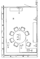
- FIG. 1 an office space 100 is shown.
- the office contains a writing-desk 10 containing equipment such as a computer terminal or personal computer having a visual display unit (VDU) 11, a conference table 20 and a number of illumination units.
- the illumination units are a desk-lamp 31 on the writing desk, three wall mounted lamps 32, 33 and 34, a free standing lamp 35, and a suspension luminaire above the conference table with a lamp 36 directed upwards for indirect illumination and two lamps 37 and 38 directed downwards for direct illumination of the table.
- the suspension luminaire has two illumination units, one being the lamp 36 and one consisting of the lamps 37 and 38, all other lamps are separate illumination units.
- the office has windows 40, at its sides, and contains further doors, cabinets, chairs and other furniture.
- the ensemble of lamps, including the required control equipment forms the illumination system.
- the tasks being performed in an office like this are, for example, reading/writing at the writing-desk 10, working with the VDU 11, and discussing around the conference table 20. Each of these tasks pose different requirements to the way the office is illuminated. There should be a moderate illumination level in the whole space while for reading/writing the desk 10 has to be sufficiently brightly illuminated, for working with the VDU 11 there should be no reflections in the screen visible while a moderate illumination of the desk 10 is acceptable.
- the area with the conference table 20 requires most illumination and possibly a section of the wall with a writing board.
- a high illumination level is required throughout the space. Different light output levels of the lamps may be desirable in the presence or absence of daylight.
- Each of the illuminations modes corresponds to a particular light output level for each of the illumination units.
- the units are provided with an identification address and so are grouped in a limited number of sets. Light output levels are identified by a step number and all units with the same identification address are switched to the same step number in each illumination mode.
- each unit comprises a programmable memory in which, for each illumination mode the step number or relative light output level for that mode is stored. When a different illumination mode is required a control signal is transmitted from a control device to all units, switching the units to the step number or light output level of the desired illumination mode.
- a possible example for the assignment of light output levels is given in the following table 1. The values entered in the table may be though of as a percentage of the maximum light output level, but are actually only labels assigned to steps.
- a living room may contain a dining table at one place, comfortable chairs at another and entertainment equipment such as a piano, television set, stereo set etcetera.
- entertainment equipment such as a piano, television set, stereo set etcetera.
- Such a place poses different requirements for illumination when dining, reading, watching television, playing the piano or listening recorded music.
- the optimum illumination will be different for tasks such as installation and maintenance of equipment, doing normal production, cleaning, and security at times that the workshop is not operational.
- FIG. 2 shows diagrammatically an illumination unit.
- the unit comprises a lamp or a plurality of lamps 200, which may be enclosed in a luminaire 201.
- the lamp is powered by a power supply, gear or ballast 210 which is adjustable to provide a different amount of power to the lamp, in response to a control signal, for example in the form of a voltage, that is supplied to a control input 211.
- the power supply comprises a power entrance 212 for connection to the mains 213.
- Such a power supply is commercially available, for example from the MCS-range of Philips Lighting.
- the control input 211 of the power supply 210 is connected to an control output 221 of a controller 220.
- the controller may be build around a control circuit 222, for example a microprocessor from the Intel MCS®-51 family.
- the controller further comprises a programmable memory 223 and a multipolar switch 224 to set an address in the controller.
- the controller 220 comprises also a receiver 225 for receiving and decoding control and programming signals from a control device 230 or from a programming device.
- the controller may be powered from the mains or may comprise a battery as its normal power source. A battery is anyway preferred as a back-up source to avoid loss of the contents of the programmable memory 223 when a mains power failure occurs.
- the power supply can provide sixteen different steps of light output levels, labelled 0 to 15.
- the level 0 is OFF and the level 15 is maximum light output.
- the steps can be implemented in the power supply 210 or, if the power supply allows a continuous change of light output or a change in very small intervals, a translation from steps to light output levels can be implemented in the control circuit 222.
- the steps can be linear, meaning that the light power for each step is changed with a certain percentage, or can be made logarithmically, i.e. to correspond to a constant interval in brightness as perceived by the user.
- An assignment of light output levels for an illumination unit with sixteen steps (numbered 0 to 15) is given in table 2. Also these levels can be considered as percentages of the maximum output level but are actually step labels.
- Communication between the control and programming devices may occur via a physically existing control connection, for example by sending control signals via the mains power lines or other wires, but preferably a wireless method for sending signals is used. This avoids a number of switches to be fixed at various places in the office, and reduces the amount of work for installing or modifying the system considerably.
- radio or ultrasone signals can be used, but infra-red signals are preferred.
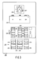
- the control device 230 comprises one or a plurality of transmitters 236 to be able to transmit signals strong enough to be detected by the receiver of each controller. In the shown embodiment it further comprises four buttons 231 to 234 for causing the control device to emit control signals corresponding to one of the illumination modes 1 to 4 and a fifth button 235 to switch off all lights.
- buttons 241 to 245 setting the address of the unit(s) to which a control sequence is to be transmitted.
- the second key pad further comprises an increase button 246 and a decrease button 247.
- the activation of one of these buttons causes a control sequence to be transmitted containing the address of the simultaneously or last pressed address button and an increase or decrease signal respectively.
- the address and the increase or decrease signal may be combined in a single code.
- An illumination unit receiving such a sequence will check if its identification address is the same as the address contained in the control sequence and, if so, change the control signal to the input 211 of the power supply 210 in order to increase or decrease the light output level.
- the second key pad also may comprise a store button 248.
- the activation of this button will cause the control device to transmit a signal to all illumination units, to store in the memory 223 the present light output level as the light output level corresponding to the present illumination mode.
- the illumination system after initialization, is controlled by exception, i. e. only those illumination units are changed of which the light output level is unsatisfactory, all other light output levels are untouched.
- the programming device 250 comprises a set 256 of infra-red light emitting diodes (IR-LED) directed in various directions to provide enough intensity in the transmitted infra-red signals to ensure proper receipt by all illumination units.
- a LED 257 emitting visible light is arranged electrically in parallel with the IR-LED's so that the operation of the LED's can be checked.
- the device comprises an ON-OFF button 251, and a first key-pad 260 with keys 261 and 262 for entering a value identifying the illumination mode, keys 263 and 264 for adjusting the address number and keys 265 and 266 for the light output level.
- a numerical key pad for entering numerical values could be used as well but that would require a larger number of keys and a larger chance for making errors.
- a window 252 for example an LCD, is provided to show the current settings of the illumination mode number, the address and the light value. The latter can be displayed as a step number or as a fraction of the maximum intensity.
- key 271 causes a signal to be send to set all illumination units for switching to the illumination mode currently entered in the programming device.
- Key 272 the "lightlevel” key sets the illumination units with the currently selected address to the light output level currently contained in the programming device.
- Key 273 “store and set mode”, causes each unit to store its present light output level as the value for the illumination mode currently set with the programming device.
- key 274, “store” causes only to store the illumination value but does not transmit a value indicating an illumination mode.
- the "off” key 275 just switches all luminaires off.
- the "all” key 276 combines the functions of the "mode”, “store” and “lightlevel” keys and will load the current light output level value under the current illumination mode in the illumination unit(s) with the current identification address, the current values being the values displayed in the window 252.
- Setting a light output level can be done, for, example, by switching the unit(s) off, and sending a number of identical increase commands whereby each command increases the light output level with one step till the required level is reached.
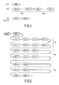
- the signal MD1 for switching all units to the first illumination mode is shown, i. e. activation of key 271 from figure 3.
- the second row shows the sequence to switch the units with identification address 2 to step number 10 or a light output level of 75 in the setting of table 2. To ascertain that the unit is off, fifteen decrease signals DC1 are transmitted, followed by ten increase signals IC1 to reach the "75" level.
- the third row shows the store signal STR followed by, again, a mode signal MD1 to store the present light level as mode 1. This is achieved by activating buttons 274 and 271, or activating button 273 alone. The full sequence can also be transmitted by activating key 276.
- a second way of programming consists of repeatedly sending to each unit in turn one increase signal till the desired light output level is reached. This is illustrated in figure 5. Firstly a mode signal MD1 is transmitted, followed by an OFF signal to switch all units to the zero level. Secondly, fifteen sequences in total of increase signals IC1, .., IC5 are transmitted. The shown sequence is for the programming of mode 1 as shown in the table 1 above. A specific increase signal is only present as long as the desired light output level in the corresponding unit(s) is not reached. As the unit with address 5 is off completely, no IC5 signals are transmitted, and because only the units with addresses 1 and 2 are to reach the maximum level, signals IC1 and IC2 are the only ones present 15 times. The sequence is terminated by a STR and a MD1 signal to store the light output levels as illumination mode 1.
- This mode of programming is preferably used in a programming device in which all predetermined light output levels for all illumination units are stored, for example in a non-volatile memory such as an EEPROM.
- a programming device in which all predetermined light output levels for all illumination units are stored, for example in a non-volatile memory such as an EEPROM.
- EEPROM electrically erasable programmable read-only memory
- Such data can be obtained by a computer simulation of the space, taking into account the known optimum light output levels at table and desk tops, walls, the reflectivity of all surfaces, the position of the illumination units, etcetera.
- Such a programming device could have only a few buttons, for selecting the illumination mode and optionally for selecting a space when modes for several spaces can be stored in the EEPROM.
- a programming device with a sufficiently large memory can be used to store several sets of illumination modes for the same space.
- Possibilities for different sets are a "test” set, entered by the manufacturer of the system and to be used by the installer or by maintenance personnel for test purposes, an "expert” set, which contains the light output level values as advised by an illumination expert for this particular space, and one or more "personal” sets entered by the normal occupant(s) of the space in accordance with his or their personal preference(s).
- a "personal” set may be derived from the "expert” set or from another person's "personal” set.
- a set of illumination units can be programmed by transmitting sequences containing an identification address, a step number value and an illumination mode value.
- the address and the step number can be transmitted as a single coded signal.
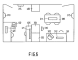
- Figure 6 shows a space having room for several occupants, each one having its own illumination system.
- a space is for example a large office space for several workers, in a living environment one could imagine a living room annex kitchen.
- two desks 301 and 401 are shown, visual display units 302 and 402, cabinets 303, 304 and 403, a conference table 305 and a wording bench 405, for example for experimentations.
- Two occupants can use this space simultaneously, and adjust the light output level to their individual needs.
- illumination units in the portion of the space for the first occupant are, for example, a suspended unit 311 above the conference table 305, a desk lamp 312 on desk 301, a free standing lamp 313 and a wall mounted lamp 314.
- the second occupant has a suspended lamp 411 above the wording bench, a desk lamp 412 on his writing desk 401, and wall mounted units 313 and 314.
- the illumination system is divided in two groups.
- the first group consists of the illumination units 311, 312, 313 and 314 for the first occupant
- the second group is formed by the units 411, 412, 413 and 414 in the second occupant's area.
- Control and programming signals are transmitted and received in different channels for the different groups, such that a signal in one channel will not influence a unit preset to receive in the other channel.
- a channel may be a separate set of coded signals that have no meaning attached to them for units of the other group.
- a channel may also be defined by a way of coding the same sequences in different patterns.
- different groups can be defined merely by the addresses of its units.
- Such a system can, for example, be applied in an industrial environment where a large number of machines and/or workers are present in the same space at the same time.
Landscapes
- Physics & Mathematics (AREA)
- General Physics & Mathematics (AREA)
- Engineering & Computer Science (AREA)
- Automation & Control Theory (AREA)
- Circuit Arrangement For Electric Light Sources In General (AREA)
Priority Applications (1)
| Application Number | Priority Date | Filing Date | Title |
|---|---|---|---|
| EP91200419A EP0482680A1 (de) | 1991-02-27 | 1991-02-27 | Programmierbares Beleuchtungssystem |
Applications Claiming Priority (1)
| Application Number | Priority Date | Filing Date | Title |
|---|---|---|---|
| EP91200419A EP0482680A1 (de) | 1991-02-27 | 1991-02-27 | Programmierbares Beleuchtungssystem |
Publications (1)
| Publication Number | Publication Date |
|---|---|
| EP0482680A1 true EP0482680A1 (de) | 1992-04-29 |
Family
ID=8207529
Family Applications (1)
| Application Number | Title | Priority Date | Filing Date |
|---|---|---|---|
| EP91200419A Withdrawn EP0482680A1 (de) | 1991-02-27 | 1991-02-27 | Programmierbares Beleuchtungssystem |
Country Status (1)
| Country | Link |
|---|---|
| EP (1) | EP0482680A1 (de) |
Cited By (45)
| Publication number | Priority date | Publication date | Assignee | Title |
|---|---|---|---|---|
| DE9310534U1 (de) * | 1993-07-15 | 1993-10-28 | Karstens, Kai, 25779 Süderheistedt | Eine Beleuchtungseinrichtung, die durch eine IR-Fernbedienung ein- bzw. ausgeschaltet werden kann und zwischen Lampenfassung und Glühbirne eingeschraubt wird |
| EP0603936A1 (de) * | 1992-12-21 | 1994-06-29 | Koninklijke Philips Electronics N.V. | Beleuchtungsanlage |
| WO1995002231A1 (en) * | 1993-07-09 | 1995-01-19 | Moe Nilssen Leif | Remote controlled switch and operating mode of same |
| EP0652690A1 (de) * | 1993-11-09 | 1995-05-10 | Laboratoires D'electronique Philips S.A.S. | Einrichtung zur automatischen Steuerung einer Beleuchtung |
| EP0669788A1 (de) * | 1994-02-24 | 1995-08-30 | Endo Lighting Corp. | Beleuchtungsdimmersystem für Leuchtstofflampen |
| US5459376A (en) * | 1992-12-21 | 1995-10-17 | U.S. Philips Corporation | Programmable lighting system with automatic light control of ambient areas |
| EP0734197A1 (de) * | 1995-03-21 | 1996-09-25 | Lutron Electronics Co., Inc. | Fernsteuersystem zur individuellen Steuerung räumlich getrennter Leuchteneinheiten |
| EP0734196A1 (de) * | 1995-03-21 | 1996-09-25 | Lutron Electronics Co., Inc. | Verbessertes System zur individuellen Fernsteuerung räumlich getrennter Leuchteneinheiten |
| US5633540A (en) * | 1996-06-25 | 1997-05-27 | Lutron Electronics Co., Inc. | Surge-resistant relay switching circuit |
| WO1998037737A1 (en) * | 1997-02-21 | 1998-08-27 | Martin Professional A/S | A system for illuminating an object |
| US5812422A (en) * | 1995-09-07 | 1998-09-22 | Philips Electronics North America Corporation | Computer software for optimizing energy efficiency of a lighting system for a target energy consumption level |
| US5987205A (en) * | 1996-09-13 | 1999-11-16 | Lutron Electronics Co., Inc. | Infrared energy transmissive member and radiation receiver |
| US6037721A (en) * | 1996-01-11 | 2000-03-14 | Lutron Electronics, Co., Inc. | System for individual and remote control of spaced lighting fixtures |
| EP1386638A1 (de) | 2002-08-02 | 2004-02-04 | Check Up s.r.l. | Beleuchtungseinrichtung |
| US6965205B2 (en) | 1997-08-26 | 2005-11-15 | Color Kinetics Incorporated | Light emitting diode based products |
| US7014336B1 (en) | 1999-11-18 | 2006-03-21 | Color Kinetics Incorporated | Systems and methods for generating and modulating illumination conditions |
| US7024119B1 (en) | 2001-11-02 | 2006-04-04 | Genlyte Thomas Group Llc | Addressable light fixture module |
| US7027736B1 (en) | 2001-11-02 | 2006-04-11 | Genlyte Thomas Group, Llc | Addressable system for light fixture modules |
| US7038399B2 (en) | 2001-03-13 | 2006-05-02 | Color Kinetics Incorporated | Methods and apparatus for providing power to lighting devices |
| US7064498B2 (en) | 1997-08-26 | 2006-06-20 | Color Kinetics Incorporated | Light-emitting diode based products |
| US7113541B1 (en) | 1997-08-26 | 2006-09-26 | Color Kinetics Incorporated | Method for software driven generation of multiple simultaneous high speed pulse width modulated signals |
| US7161311B2 (en) | 1997-08-26 | 2007-01-09 | Color Kinetics Incorporated | Multicolored LED lighting method and apparatus |
| US7178941B2 (en) | 2003-05-05 | 2007-02-20 | Color Kinetics Incorporated | Lighting methods and systems |
| US7186003B2 (en) | 1997-08-26 | 2007-03-06 | Color Kinetics Incorporated | Light-emitting diode based products |
| US7202613B2 (en) | 2001-05-30 | 2007-04-10 | Color Kinetics Incorporated | Controlled lighting methods and apparatus |
| US7221104B2 (en) | 1997-08-26 | 2007-05-22 | Color Kinetics Incorporated | Linear lighting apparatus and methods |
| DE102006013693A1 (de) * | 2006-03-24 | 2007-11-15 | Handlbauer, Gerhard | Infrarot steuerbarer Dimmer für EVG's |
| US7300192B2 (en) | 2002-10-03 | 2007-11-27 | Color Kinetics Incorporated | Methods and apparatus for illuminating environments |
| US7303300B2 (en) | 2000-09-27 | 2007-12-04 | Color Kinetics Incorporated | Methods and systems for illuminating household products |
| WO2007119126A3 (en) * | 2005-03-23 | 2007-12-21 | Koninkl Philips Electronics Nv | Self-learning lighting system |
| SG137689A1 (en) * | 2002-03-08 | 2007-12-28 | Nanyang Polytechnic | Programmable illumination controller |
| US7352339B2 (en) | 1997-08-26 | 2008-04-01 | Philips Solid-State Lighting Solutions | Diffuse illumination systems and methods |
| US7358679B2 (en) | 2002-05-09 | 2008-04-15 | Philips Solid-State Lighting Solutions, Inc. | Dimmable LED-based MR16 lighting apparatus and methods |
| US7427840B2 (en) | 1997-08-26 | 2008-09-23 | Philips Solid-State Lighting Solutions, Inc. | Methods and apparatus for controlling illumination |
| US7453217B2 (en) | 1997-08-26 | 2008-11-18 | Philips Solid-State Lighting Solutions, Inc. | Marketplace illumination methods and apparatus |
| US7598681B2 (en) | 2001-05-30 | 2009-10-06 | Philips Solid-State Lighting Solutions, Inc. | Methods and apparatus for controlling devices in a networked lighting system |
| US7598686B2 (en) | 1997-12-17 | 2009-10-06 | Philips Solid-State Lighting Solutions, Inc. | Organic light emitting diode methods and apparatus |
| EP1986474A3 (de) * | 2007-04-26 | 2010-10-20 | Everbright Optech Inc. | Verfahren und System zur Steuerung einer Farbbeleuchtungsvorrichtung |
| US7845823B2 (en) | 1997-08-26 | 2010-12-07 | Philips Solid-State Lighting Solutions, Inc. | Controlled lighting methods and apparatus |
| US7868562B2 (en) | 2006-12-11 | 2011-01-11 | Koninklijke Philips Electronics N.V. | Luminaire control system and method |
| EP2302983A2 (de) | 2006-12-08 | 2011-03-30 | Koninklijke Philips Electronics N.V. | Lichtquelle |
| EP1421632B2 (de) † | 2001-07-03 | 2015-01-07 | Face International Corporation | Selbstversorgendes schalterinitialisierungssystem |
| US9069341B2 (en) | 2006-12-11 | 2015-06-30 | Koninklijke Philips N.V. | Method and apparatus for digital control of a lighting device |
| US10009709B2 (en) | 2015-03-26 | 2018-06-26 | Medea Inc. | Electronic device with network access via mobile device proxy |
| US10044915B2 (en) | 2012-06-01 | 2018-08-07 | Medea Inc. | Container with camera and electronic display |
Citations (6)
| Publication number | Priority date | Publication date | Assignee | Title |
|---|---|---|---|---|
| GB2070830A (en) * | 1980-02-25 | 1981-09-09 | Toshiba Electric Equip | Remote lighting-control apparatus |
| EP0069470A1 (de) * | 1981-06-08 | 1983-01-12 | Pittway Corporation | Gerätsteuerungssystem |
| FR2530839A1 (fr) * | 1982-07-22 | 1984-01-27 | Ramanantsoa Johnson | Systeme de gradation de puissance a distribution monoligne des commandes et de l'energie |
| EP0253082A2 (de) * | 1986-07-17 | 1988-01-20 | Vari-Lite, Inc. | Rechnergesteuerte Beleuchtungseinrichtung mit verteilter Verarbeitung |
| WO1988004517A1 (en) * | 1986-12-04 | 1988-06-16 | Lightolier Incorporated | Programmable multicircuit wall-mounted controller |
| DE3719384A1 (de) * | 1987-06-05 | 1988-12-22 | Semperlux Gmbh | Leuchtensystem aus frei einstell- und steuerbaren lichtquellen |
-
1991
- 1991-02-27 EP EP91200419A patent/EP0482680A1/de not_active Withdrawn
Patent Citations (6)
| Publication number | Priority date | Publication date | Assignee | Title |
|---|---|---|---|---|
| GB2070830A (en) * | 1980-02-25 | 1981-09-09 | Toshiba Electric Equip | Remote lighting-control apparatus |
| EP0069470A1 (de) * | 1981-06-08 | 1983-01-12 | Pittway Corporation | Gerätsteuerungssystem |
| FR2530839A1 (fr) * | 1982-07-22 | 1984-01-27 | Ramanantsoa Johnson | Systeme de gradation de puissance a distribution monoligne des commandes et de l'energie |
| EP0253082A2 (de) * | 1986-07-17 | 1988-01-20 | Vari-Lite, Inc. | Rechnergesteuerte Beleuchtungseinrichtung mit verteilter Verarbeitung |
| WO1988004517A1 (en) * | 1986-12-04 | 1988-06-16 | Lightolier Incorporated | Programmable multicircuit wall-mounted controller |
| DE3719384A1 (de) * | 1987-06-05 | 1988-12-22 | Semperlux Gmbh | Leuchtensystem aus frei einstell- und steuerbaren lichtquellen |
Cited By (62)
| Publication number | Priority date | Publication date | Assignee | Title |
|---|---|---|---|---|
| EP0603936A1 (de) * | 1992-12-21 | 1994-06-29 | Koninklijke Philips Electronics N.V. | Beleuchtungsanlage |
| US5459376A (en) * | 1992-12-21 | 1995-10-17 | U.S. Philips Corporation | Programmable lighting system with automatic light control of ambient areas |
| WO1995002231A1 (en) * | 1993-07-09 | 1995-01-19 | Moe Nilssen Leif | Remote controlled switch and operating mode of same |
| DE9310534U1 (de) * | 1993-07-15 | 1993-10-28 | Karstens, Kai, 25779 Süderheistedt | Eine Beleuchtungseinrichtung, die durch eine IR-Fernbedienung ein- bzw. ausgeschaltet werden kann und zwischen Lampenfassung und Glühbirne eingeschraubt wird |
| EP0652690A1 (de) * | 1993-11-09 | 1995-05-10 | Laboratoires D'electronique Philips S.A.S. | Einrichtung zur automatischen Steuerung einer Beleuchtung |
| EP0669788A1 (de) * | 1994-02-24 | 1995-08-30 | Endo Lighting Corp. | Beleuchtungsdimmersystem für Leuchtstofflampen |
| AU696567B2 (en) * | 1995-03-21 | 1998-09-10 | Lutron Electronics Co., Inc. | Remote control system for individual control of spaced lighting fixtures |
| EP0734197A1 (de) * | 1995-03-21 | 1996-09-25 | Lutron Electronics Co., Inc. | Fernsteuersystem zur individuellen Steuerung räumlich getrennter Leuchteneinheiten |
| EP0734196A1 (de) * | 1995-03-21 | 1996-09-25 | Lutron Electronics Co., Inc. | Verbessertes System zur individuellen Fernsteuerung räumlich getrennter Leuchteneinheiten |
| AU701880B2 (en) * | 1995-03-21 | 1999-02-11 | Lutron Electronics Co., Inc. | Improved system for individual and remote control of spaced lighting fixtures |
| US5637964A (en) * | 1995-03-21 | 1997-06-10 | Lutron Electronics Co., Inc. | Remote control system for individual control of spaced lighting fixtures |
| US5812422A (en) * | 1995-09-07 | 1998-09-22 | Philips Electronics North America Corporation | Computer software for optimizing energy efficiency of a lighting system for a target energy consumption level |
| US6037721A (en) * | 1996-01-11 | 2000-03-14 | Lutron Electronics, Co., Inc. | System for individual and remote control of spaced lighting fixtures |
| US6310440B1 (en) | 1996-01-11 | 2001-10-30 | Lutron Electronics Company, Inc. | System for individual and remote control of spaced lighting fixtures |
| US5633540A (en) * | 1996-06-25 | 1997-05-27 | Lutron Electronics Co., Inc. | Surge-resistant relay switching circuit |
| US5987205A (en) * | 1996-09-13 | 1999-11-16 | Lutron Electronics Co., Inc. | Infrared energy transmissive member and radiation receiver |
| WO1998037737A1 (en) * | 1997-02-21 | 1998-08-27 | Martin Professional A/S | A system for illuminating an object |
| US7274160B2 (en) | 1997-08-26 | 2007-09-25 | Color Kinetics Incorporated | Multicolored lighting method and apparatus |
| US7221104B2 (en) | 1997-08-26 | 2007-05-22 | Color Kinetics Incorporated | Linear lighting apparatus and methods |
| US7352339B2 (en) | 1997-08-26 | 2008-04-01 | Philips Solid-State Lighting Solutions | Diffuse illumination systems and methods |
| US7845823B2 (en) | 1997-08-26 | 2010-12-07 | Philips Solid-State Lighting Solutions, Inc. | Controlled lighting methods and apparatus |
| US6965205B2 (en) | 1997-08-26 | 2005-11-15 | Color Kinetics Incorporated | Light emitting diode based products |
| US7427840B2 (en) | 1997-08-26 | 2008-09-23 | Philips Solid-State Lighting Solutions, Inc. | Methods and apparatus for controlling illumination |
| US7064498B2 (en) | 1997-08-26 | 2006-06-20 | Color Kinetics Incorporated | Light-emitting diode based products |
| US7113541B1 (en) | 1997-08-26 | 2006-09-26 | Color Kinetics Incorporated | Method for software driven generation of multiple simultaneous high speed pulse width modulated signals |
| US7161311B2 (en) | 1997-08-26 | 2007-01-09 | Color Kinetics Incorporated | Multicolored LED lighting method and apparatus |
| US7453217B2 (en) | 1997-08-26 | 2008-11-18 | Philips Solid-State Lighting Solutions, Inc. | Marketplace illumination methods and apparatus |
| US7186003B2 (en) | 1997-08-26 | 2007-03-06 | Color Kinetics Incorporated | Light-emitting diode based products |
| US7462997B2 (en) | 1997-08-26 | 2008-12-09 | Philips Solid-State Lighting Solutions, Inc. | Multicolored LED lighting method and apparatus |
| US7520634B2 (en) | 1997-12-17 | 2009-04-21 | Philips Solid-State Lighting Solutions, Inc. | Methods and apparatus for controlling a color temperature of lighting conditions |
| US7598686B2 (en) | 1997-12-17 | 2009-10-06 | Philips Solid-State Lighting Solutions, Inc. | Organic light emitting diode methods and apparatus |
| US7387405B2 (en) | 1997-12-17 | 2008-06-17 | Philips Solid-State Lighting Solutions, Inc. | Methods and apparatus for generating prescribed spectrums of light |
| US7255457B2 (en) | 1999-11-18 | 2007-08-14 | Color Kinetics Incorporated | Methods and apparatus for generating and modulating illumination conditions |
| US7350936B2 (en) | 1999-11-18 | 2008-04-01 | Philips Solid-State Lighting Solutions, Inc. | Conventionally-shaped light bulbs employing white LEDs |
| US7014336B1 (en) | 1999-11-18 | 2006-03-21 | Color Kinetics Incorporated | Systems and methods for generating and modulating illumination conditions |
| US7652436B2 (en) | 2000-09-27 | 2010-01-26 | Philips Solid-State Lighting Solutions, Inc. | Methods and systems for illuminating household products |
| US7303300B2 (en) | 2000-09-27 | 2007-12-04 | Color Kinetics Incorporated | Methods and systems for illuminating household products |
| US7352138B2 (en) | 2001-03-13 | 2008-04-01 | Philips Solid-State Lighting Solutions, Inc. | Methods and apparatus for providing power to lighting devices |
| US7038399B2 (en) | 2001-03-13 | 2006-05-02 | Color Kinetics Incorporated | Methods and apparatus for providing power to lighting devices |
| US7598681B2 (en) | 2001-05-30 | 2009-10-06 | Philips Solid-State Lighting Solutions, Inc. | Methods and apparatus for controlling devices in a networked lighting system |
| US7598684B2 (en) | 2001-05-30 | 2009-10-06 | Philips Solid-State Lighting Solutions, Inc. | Methods and apparatus for controlling devices in a networked lighting system |
| US7202613B2 (en) | 2001-05-30 | 2007-04-10 | Color Kinetics Incorporated | Controlled lighting methods and apparatus |
| US7550931B2 (en) | 2001-05-30 | 2009-06-23 | Philips Solid-State Lighting Solutions, Inc. | Controlled lighting methods and apparatus |
| EP1421632B2 (de) † | 2001-07-03 | 2015-01-07 | Face International Corporation | Selbstversorgendes schalterinitialisierungssystem |
| US7024119B1 (en) | 2001-11-02 | 2006-04-04 | Genlyte Thomas Group Llc | Addressable light fixture module |
| US7027736B1 (en) | 2001-11-02 | 2006-04-11 | Genlyte Thomas Group, Llc | Addressable system for light fixture modules |
| SG137689A1 (en) * | 2002-03-08 | 2007-12-28 | Nanyang Polytechnic | Programmable illumination controller |
| US7358679B2 (en) | 2002-05-09 | 2008-04-15 | Philips Solid-State Lighting Solutions, Inc. | Dimmable LED-based MR16 lighting apparatus and methods |
| EP1386638B1 (de) * | 2002-08-02 | 2008-09-03 | Check up S.p.A. | Beleuchtungseinrichtung |
| EP1386638A1 (de) | 2002-08-02 | 2004-02-04 | Check Up s.r.l. | Beleuchtungseinrichtung |
| US7300192B2 (en) | 2002-10-03 | 2007-11-27 | Color Kinetics Incorporated | Methods and apparatus for illuminating environments |
| US7178941B2 (en) | 2003-05-05 | 2007-02-20 | Color Kinetics Incorporated | Lighting methods and systems |
| CN101218856B (zh) * | 2005-03-23 | 2012-02-29 | 皇家飞利浦电子股份有限公司 | 自学习照明系统 |
| WO2007119126A3 (en) * | 2005-03-23 | 2007-12-21 | Koninkl Philips Electronics Nv | Self-learning lighting system |
| DE102006013693A1 (de) * | 2006-03-24 | 2007-11-15 | Handlbauer, Gerhard | Infrarot steuerbarer Dimmer für EVG's |
| EP2302983A2 (de) | 2006-12-08 | 2011-03-30 | Koninklijke Philips Electronics N.V. | Lichtquelle |
| US9069341B2 (en) | 2006-12-11 | 2015-06-30 | Koninklijke Philips N.V. | Method and apparatus for digital control of a lighting device |
| US7868562B2 (en) | 2006-12-11 | 2011-01-11 | Koninklijke Philips Electronics N.V. | Luminaire control system and method |
| EP1986474A3 (de) * | 2007-04-26 | 2010-10-20 | Everbright Optech Inc. | Verfahren und System zur Steuerung einer Farbbeleuchtungsvorrichtung |
| US10044915B2 (en) | 2012-06-01 | 2018-08-07 | Medea Inc. | Container with camera and electronic display |
| US10009709B2 (en) | 2015-03-26 | 2018-06-26 | Medea Inc. | Electronic device with network access via mobile device proxy |
| US10433138B2 (en) | 2015-03-26 | 2019-10-01 | Medea Inc. | Electronic device with network access via mobile device proxy |
Similar Documents
| Publication | Publication Date | Title |
|---|---|---|
| KR100313553B1 (ko) | 원격 감시 제어 시스템 | |
| US9035572B1 (en) | Combined lighting device with an integrated dimming control system | |
| US8288957B2 (en) | System for controlling light sources | |
| JP2000516024A (ja) | 仮想的無制限の帯域容量をもつ壁装着可能な制御システム | |
| CA2524635A1 (en) | Digital addressable electronic ballast and control unit | |
| NO175958B (no) | Styringssystem for flere apparater | |
| CN1494724A (zh) | 开关单元 | |
| CN114600051A (zh) | 环境控制系统 | |
| US20170064795A1 (en) | Luminaire for illuminating an area of a building, in particular an office | |
| US20020014972A1 (en) | Control station for control system with automatic detection and configuration of control elements | |
| EP0364466A1 (de) | Elektrische steuervorrichtung | |
| WO2006048916A2 (en) | Lighting system with remote control | |
| KR100284629B1 (ko) | 조명 시스템 | |
| EP1480497B1 (de) | System zur Fernsteuerung von Leuchtvorrichtungen | |
| JP2002110366A (ja) | 照明制御監視システム | |
| EP0603936B1 (de) | Beleuchtungsanlage | |
| KR101828321B1 (ko) | 조명 제어 시스템 및 방법 | |
| KR200176548Y1 (ko) | 조명 제어장치 | |
| EP3726781B1 (de) | Abbildung und inbetriebnahme von elektrischen vorrichtungen in einer automatisierten heimumgebung | |
| KR100294241B1 (ko) | 조명제어장치 | |
| JP2024136969A (ja) | 制御システム | |
| JPH05242973A (ja) | 照明機器コントローラ及びその利用方法 | |
| GB2390204A (en) | Control system e.g. for controlling electrical lights | |
| JPH05504239A (ja) | 複数の被給電装置に対する制御システム及びそれを作動させる方法 | |
| JPH02162690A (ja) | 照明システム |
Legal Events
| Date | Code | Title | Description |
|---|---|---|---|
| PUAI | Public reference made under article 153(3) epc to a published international application that has entered the european phase |
Free format text: ORIGINAL CODE: 0009012 |
|
| AK | Designated contracting states |
Kind code of ref document: A1 Designated state(s): AT BE CH DE DK ES FR GB GR IT LI LU NL SE |
|
| RBV | Designated contracting states (corrected) |
Designated state(s): DE |
|
| 17P | Request for examination filed |
Effective date: 19921029 |
|
| STAA | Information on the status of an ep patent application or granted ep patent |
Free format text: STATUS: THE APPLICATION IS DEEMED TO BE WITHDRAWN |
|
| 18D | Application deemed to be withdrawn |
Effective date: 19940901 |