EP0482722A2 - Greiferführung für Doppelgreiferwebmaschinen - Google Patents
Greiferführung für Doppelgreiferwebmaschinen Download PDFInfo
- Publication number
- EP0482722A2 EP0482722A2 EP91202774A EP91202774A EP0482722A2 EP 0482722 A2 EP0482722 A2 EP 0482722A2 EP 91202774 A EP91202774 A EP 91202774A EP 91202774 A EP91202774 A EP 91202774A EP 0482722 A2 EP0482722 A2 EP 0482722A2
- Authority
- EP
- European Patent Office
- Prior art keywords
- gripper
- guide
- strip
- fixed
- slide
- Prior art date
- Legal status (The legal status is an assumption and is not a legal conclusion. Google has not performed a legal analysis and makes no representation as to the accuracy of the status listed.)
- Granted
Links
Images


Classifications
-
- D—TEXTILES; PAPER
- D03—WEAVING
- D03D—WOVEN FABRICS; METHODS OF WEAVING; LOOMS
- D03D47/00—Looms in which bulk supply of weft does not pass through shed, e.g. shuttleless looms, gripper shuttle looms, dummy shuttle looms
- D03D47/27—Drive or guide mechanisms for weft inserting
- D03D47/275—Drive mechanisms
- D03D47/276—Details or arrangement of sprocket wheels
-
- D—TEXTILES; PAPER
- D03—WEAVING
- D03D—WOVEN FABRICS; METHODS OF WEAVING; LOOMS
- D03D47/00—Looms in which bulk supply of weft does not pass through shed, e.g. shuttleless looms, gripper shuttle looms, dummy shuttle looms
- D03D47/12—Looms in which bulk supply of weft does not pass through shed, e.g. shuttleless looms, gripper shuttle looms, dummy shuttle looms wherein single picks of weft thread are inserted, i.e. with shedding between each pick
-
- D—TEXTILES; PAPER
- D03—WEAVING
- D03D—WOVEN FABRICS; METHODS OF WEAVING; LOOMS
- D03D47/00—Looms in which bulk supply of weft does not pass through shed, e.g. shuttleless looms, gripper shuttle looms, dummy shuttle looms
- D03D47/27—Drive or guide mechanisms for weft inserting
- D03D47/271—Rapiers
- D03D47/273—Rapier rods
-
- D—TEXTILES; PAPER
- D03—WEAVING
- D03D—WOVEN FABRICS; METHODS OF WEAVING; LOOMS
- D03D47/00—Looms in which bulk supply of weft does not pass through shed, e.g. shuttleless looms, gripper shuttle looms, dummy shuttle looms
- D03D47/27—Drive or guide mechanisms for weft inserting
- D03D47/277—Guide mechanisms
-
- D—TEXTILES; PAPER
- D03—WEAVING
- D03J—AUXILIARY WEAVING APPARATUS; WEAVERS' TOOLS; SHUTTLES
- D03J1/00—Auxiliary apparatus combined with or associated with looms
Definitions
- the present invention relates to the device for guiding the gripper bars of a double-gripper weaving machine.
- provision is made along both sides of the shed formed between the warp threads for a device for driving and a device for guiding two gripper bars lying one above the other.
- a gripper is situated on the end of each gripper bar.
- the grippers lying in line with each other are taken for each pick simultaneously along both sides of the fabric into the open shed, a weft thread being taken along by one of the grippers and in the shed passed on to the other gripper at the place where the two grippers meet, following which both grippers are pulled back out of the shed, so that the weft thread in the end is pulled from one side of the fabric to the other side, through the shed.
- This cycle is repeated each time a shed is formed, a weft thread being taken in each case from one side of the fabric to the other and woven with the warp threads.
- the drive of the gripper bars is preferably carried out by means of drive gear wheels which mesh with toothed sides of said gripper bars.
- Guide means also have to be provided for each gripper bar, so that the grippers cover the desired path during their to and fro movement.
- a known guide device is described in Belgian Patent 8,701,166.
- This gripper guide comprises, on the one hand, a number of rollers which are situated at the level of the drive gear wheel with their cylindrical surface against the gripper bars, in such a way that the gripper bars move between the rollers and their respective drive gear wheel. These rollers guide the gripper bars in such a way that they interact well with the drive gear wheel.
- This known gripper guide also comprises two guides contoured in an L-shape, each of which is provided to guide one of the gripper bars which in this case, being provided with a slipper on their ends, glide to and fro in the angle formed by their L-shaped guide, while the horizontal part of the guides is situated below the gripper bars.
- the known gripper guide also comprises two guide tables which are provided to guide the gripper bar heads. These tables are fixed so that they are adjustable in height, weft direction and warp direction.
- this gripper guide is each interconnected adjustably to form one unit, while the unit is adjustably connected to the frame of the weaving machine.
- the guides are each accommodated so that they are adjustable in height in a channel section which is fixed to the gripper guide housing.
- the gripper guide housing can rotate relative to the drive shaft.
- a disadvantage of this gripper guide lies in the fact that, due to the L-shaped guides, the gripper bars are guided only along the bottom side and the rear side, as a result of which they swing forward on their to and fro movement. The result of this is that the roller guide operates operates jerkily, causing uneven wear to occur on the back of the gripper bars. The backs of the gripper bars become uneven, so that the guide rollers absorb increasingly strong impact forces. The bearings of the guide rollers are consequently subjected to great wear, so that these bearings in the end become defective after quite a short period of operation.
- Another disadvantage of this gripper guide is that the play between the drive gear wheels and the corresponding gripper bars is difficult to set.
- the L-shaped guides are only (jointly) rotatable relative to the gripper guide housing, in addition to their common adjustability in height. This gives rise to another disadvantage, namely that individual setting of the gripper guide for each gripper bar separately is not possible.
- the object of the invention is to provide a device for guiding the gripper bars of a double-gripper weaving machine which eliminates the above-mentioned disadvantages.
- a subject of the invention is a gripper guide for double-gripper weaving machines, with a bearing housing in which drive gear wheels are disposed, and two horizontal bearing arms running above one another, each fixed so as to be adjustable in the warp direction, while at the front side of each of said bearing arms a guide strip with essentially L-shaped cross-section is fixed so that it is adjustable in height.
- This L-shaped guide strip is disposed in such a way that one of the angle-forming faces is fixed upright against a bearing arm, while the other angle-forming face extends forward from the bottom side of the upright face.
- These L-shaped guide strips end at one side where the drive gear wheels project from the bearing housing and at the other side where the bearing arms end.
- a short L-shaped guide piece which is adjustable in height and in the warp direction is fixed to a fixed part of the machine.
- the gripper guide according to the invention also has a slide strip, disposed at a short distance before each L-shaped guide strip and parallel thereto at the same height, so that each L-shaped guide strip and the slide strip running before it form a U-shaped guide channel. Both slide strips are each individually fixed to their respective bearing arm with a connection which permits easy and rapid removal of the slide strips to free the U-shaped channel along the front side.
- Each slide strip - or its connection devices to a carrier arm - is also provided with one or more adjusting screws by which the distance between the respective L-shaped guide strips and the slide strip fixed before them can be adjusted individually.
- the gripper guide according to the invention can also be equipped with means for guiding the gripper bars even closer to the fabric edge. These means are in this case adjustable in warp direction, in weft direction and in height.
- the gripper guide according to the invention also has in the slide strip at least one dry lubricating device which can lubricate the gripper bar during its sliding to and fro movement.
- the slide strip has at the level of the gripper drive wheel a lower-lying part, on which one or more rollers are fixed on a vertical shaft, in such a way that they can guide the gripper bar with their cylindrical surface while they are rotating.
- the gripper bars are moved to and fro by the gripper gear wheels, so that they slide in the U-shaped guide channels situated above one another.
- the bearing arms are individually adjustable in the warp direction
- the L-shaped guide pieces are also adjustable individually in height.
- the slide strips are also adjustable individually in the warp direction relative to the L-shaped guide strips.
- An advantage of the invention lies in the fact that the gripper bars are now also guided along the front side, which prevents swing of the gripper bars and limits the wear on various parts.
- Another advantage of the invention lies in the fact that both the height of the guide and the play between gripper bar and drive gear wheel can be set for each gripper bar.
- Another subject of the invention is a double-gripper weaving machine equipped with a gripper guide according to the invention.
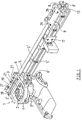
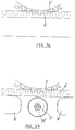
- a preferred embodiment of a gripper guide according to the invention is shown in perspective by means of Figures 1, 2, 6 and 7, a rear view, a front view, and two side views respectively.
- the gripper guide is in each case shown with the drive unit to which it is attached. Situated along each side of the weaving machine is such a gripper guide with drive device extending in the weft direction towards the centre of the weaving machine, the arrangement along one side being such that it is the mirror image of the arrangement along the other side, relative to the centre of the weaving machine.
- the arrangement of Figures 1 and 2 is suitable for placing on the left side of the machine, at the level of the shed (viewed from the fabric side), while the arrangement of Figures 6 and 7 is suitable for placing on the right side.
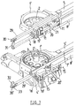
- the gripper guide and the drive unit attached thereto are each composed of two parts which are attached to each other and are composed of the same components, each part handling the drive and guidance of one of the gripper bars (see Figs. 2, 6 and 7).
- a housing (1) is situated at the level of the place where the shed is formed, said housing being semi-cylindrical in shape, with the flat side facing forward, and in which two drive gear wheels (2) and (2') are disposed on a shaft (3) one above the other.
- the housing (1) is composed of two identical parts (1) and (1') which are fixed on each other, and each of which contains a drive gear wheel (2) and (2').
- the sides of the gripper bars (4) and (4') facing the drive gear wheels (2), (2') are provided with teeth for meshing with the drive gear wheels (2) and (2') over the distance needed to move the grippers situated on the ends of the gripper bars (4) and (4') into and out of the shed.
- An identical horizontal bearing arm (5) and (5') extending laterally in the weft direction towards the outside is fixed on the side wall of each part (1') and (1'') of the housing (1) facing the outside of the weaving machine.
- the bearing arm (5) is in this case situated on top of the bearing arm (5'), and both bearing arms run together over the same length.
- Each bearing arm (5) and (5') is fixed individually to the wall of part (1') and (1'') of the housing (1).
- the end of each bearing arm widens out for this purpose and is provided with an elongated aperture (6) and (6') extending in the warp direction (see Fig. 1).
- the L-shaped guide strips (7) and (7') are fixed to the bearing arms (5) and (5') respectively in such a way that said strips are individually adjustable in height, through the fact that vertical apertures (5'') are provided in said bearing arms (5) and (5'), through which apertures the fixing screws project when screwed into the respective L-shaped guide strips (7) and (7').
- Each L-shaped guide strip (7) and (7') is fixed in this way with several screws, which are distributed over the length of the guide strip (7) and (7').
- each of the two L-shaped guide strips (7) and (7') is a slide strip (8) and (8'), parallel to and at the same height as the respective guide strips (7) and (7'), and at a distance in front of the upright flank of said L-shaped guide strips which - apart from a slight play - corresponds to the width of the gripper bars (4) and (4') (see Fig. 4).
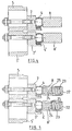
- a slide strip (8) and (8') is hingedly fixed as follows relative to the bearing arms (5) and (5').
- a hinge (9) Fixed at the top side of the upper bearing arm (5) at one side - on the one end - is the fixed part of a hinge (9), the hinged part of which is fixed to the front flank of the top slide strip (8).
- the fixed part of a hinge (10) is fixed to the housing (1), extending above the top U-shaped guide channel, while the hinged part of said hinge (10) is fixed to the slide strip (8).
- Each of said hinges (9) and (10) is also equipped with at least one buffer block or similar part which is integral with the fixed part, and against which the hinged parts knock when the slide strip (8) is situated opposite the L-shaped guide strip (7), ready for guiding the upper gripper bar (4). The correct position of the slide strip (8) is determined in this way.
- the hinged part can be fixed by means of screws (11) to the buffer block or similar component of the fixed part.
- the fixing of the hinge (9) to the front flank of the slide strip (8) is by means of a screw (12).
- the slide strip (8) can be flapped up after loosening of the screws (11).
- the fixing of the fixed part of the hinge (9) is by means of two screws (26) sitting through elongated apertures in said hinge (9). Said apertures extend in the warp direction, so that with the screws (26) the slide strip (8) can be set at the level of the hinge (9) closer to or further away from the L-shaped guide strip (7).
- the slide strip (8) is adjustable in the warp direction by means of two screws (27) which sit through elongated apertures extending in the warp direction through hinge (10).
- the setting in height can take place by the insertion of plates between the hinge (10) and the slide strip (8) fixed thereto.
- a short L-shaped supporting section (17) is fixed to the frame of the weaving machine.
- the horizontal part of said supporting section (17) is at the correct height for supporting the lower bearing arm (5').
- Said supporting section (17) is fixed to the weaving machine in a manner which is adjustable in height, by providing the fixing flank of said supporting section (17) with an aperture extending in the vertical direction, through which the fixing screws project and are screwed into the frame of the machine.
- the preferred embodiment of the gripper guide according to the invention is also equipped with a short section (18) and (18') (see Fig. 6) with L-shaped cross-section in line with each L-shaped guide piece (7) and (7') fixed to the housing (1) or another fixed part of the weaving machine.
- Said sections (18) and (18') are provided for guiding the gripper bars (4), (4'), past the place where the drive gear wheels (2), (2') project from the housing (1).
- Their fixing to the housing (1) or another fixed part is such that the arrangement can be altered both in height and in the warp direction.
- each section (18) and (18') has a horizontal arm which is provided with an elongated aperture, extending in the warp direction, for fixing with a screw, bolt and nut, or similar means. Through this elongated aperture, each section (18) and (18') is adjustable in the warp direction.
- Both sections (18) and (18') are fixed to an L-shaped fixing piece (19), (19') respectively which are adjustable in height, one leg of the fixing piece (19) and (19') being fixed against the horizontal arm of the section (18), (18') respectively, while the other angle-forming leg is fixed to a fixed part of the weaving machine by means of a screw, a bolt and nut, or similar connecting device which sits through an elongated vertically extending aperture of the fixing piece (19), (19') respectively, as a result of which said fixing pieces (19) and (19'), and consequently also the sections (18), (18') respectively fixed thereto, are adjustable in height.
- the preferred embodiment of the gripper guide according to the invention is also characterised in that a roller (20) and (20') is disposed on the top side of each slide strip (8) and (8'), at the same width for both slide strips (8) and (8'), at the level of the drive gear wheels (2), (2') respectively.
- These rollers (20) and (20') are situated on a vertical shaft (21) and are disposed in such a way that with their cylindrical surface they can guide the gripper bars (4), (4') respectively which slide to and fro behind the slide strips (8) and (8').
- Each slide strip (8) and (8') preferably also contains a dry lubricating device, shown in a preferred embodiment in Figure 5.
- each slide strip (8), (8') can be shut off by means of a cover, screw cap or similar means (22). Resting against the inside of said screw cap (22) is a spring (23), whose other side presses against a teflon stick (24). The end of said teflon stick (24), or the part which is fixed on said end, against which the spring (23) presses, is provided with a widened part (25). The other end of the teflon stick (24) projects out through the aperture in the wall of the slide strip (8) or (8') and presses against the gripper bars (4), (4') respectively.
- the widened part (25) is of such dimensions relative to the aperture through which the stick (24) projects that it is impossible for the teflon stick (24) to come completely out of the slide strip (8) or (8').
- the screw cap (22) or cover can be screwed as desired further or less far into the internal screw thread which is provided in the hollow space or bore through the slide strip (8), (8'), so that the spring (23) exerts more or less pressure on the teflon stick (24) which is pressed against the front flank of the gripper bar (4) or (4').
- the vertical flanks of the slide strips (8) and (8') along the edge of the gripper bars (4), (4') are provided with an anti-friction surface coating.
- the housing (1) of the drive gear wheels (2) and (2') is also provided with means for fixing a suspension bar to which then - corresponding to Belgian Patent No. 8,701,166 - adjustable guide means are fixed, for guiding the gripper bars (4) and (4') even closer to the fabric edge.
- the housing (1) of the drive gear wheels (2), (2') is provided (see Figure 1) with a horizontally extending U-shaped recess (28) along the top side of the upper part (1') of the housing (1), and with an identical recess (not visible in the figures) along the bottom side of the lower part (1'') of the housing (1).
- a suspension bar (29), (29') extending further than the housing (1) in the direction of the fabric, in the weft direction, is fixed in these second slits (28).
- These suspension bars (29), (29') each have a part (30), (30') which can slide out in line with them in the direction of the fabric, and which can be adjusted at any desired extended length and fixed by means of a clamping screw or similar device.
- a guide piece (31) extending vertically downward is fixed on the end of the telescopic part (30) of the upper suspension bar (29).
- Said guide piece (31) has a lower part which is essentially C-shaped, the open side being situated along the front side.
- the space enclosed by the C-shaped part has a cross-section which, apart from a certain play, corresponds to the cross-section of the gripper bar (4), in such a way that said gripper bar (4), extending from the gripper guide, can extend through said space enclosed by the C-shaped part, resting on the lower horizontal internal face of said C-shaped part.
- the gripper bar (4) is consequently guided by the guide piece (31) along the bottom side, the top side and the rear side.
- Said guide piece (31) is fixed so that it is adjustable in height - by means of a screw (31') sitting through an elongated aperture extending vertically - to the part (30) of the suspension bar (29). Due to the fact that the part (30) is telescopic, the guide piece (31) is also adjustable in the weft direction. In addition, the guide piece (31) is adjustable in the warp direction.
- a micrometer screw (31'') is provided (see Figure 8), by means of which a displacement in the warp direction of the part (30), and thus of the guide piece (31), relative to the suspension bar (29) can be obtained. Before this adjustment is carried out, a screw (31'') must be loosened. After the correct adjustment, said screw (31'') is tightened again.
- An L-shaped guide piece (32) is fixed on the end of the telescopic part (30') of the lower suspension bar (29'), with the one angle-forming part parallel to the horizontal top face of the telescopic part (30'), and with the other angle-forming part, at right angles thereto - on the rear edge thereof - directed upwards, the upright part extending parallel to the lengthwise direction of the suspension bar (29').
- this L-shaped guide piece (32) has along the bottom side of the horizontal part a vertically downward directed plate (33) which abuts the front flank of the part (30') of the suspension bar (29').
- This plate (33) is provided with an upward extending, elongated hole for a screw (33'), which is tightened in the front flank of the part (30') of the suspension bar (29'), as a result of which the L-shaped guide piece (32) is fixed so that it is adjustable in height. Due to the fact that the part (30') is telescopic, the L-shaped guide piece (32) is also adjustable in the weft direction.
- the guide piece (32) is also adjustable in the warp direction.
- a micrometer screw (33''') is provided (see Figure 8), by means of which a displacement in the warp direction of the part (30), and thus of the guide piece (32), relative to the suspension bar (29') can be obtained.
- a screw (33'') must be loosened. After the correct adjustment, said screw (33'') is tightened again.
- An advantage of the invention is in the first place that swing of the gripper bars is prevented through the provision of a slide strip (8), (8') along the front side of each gripper bar (4), (4').
- the wear on the gripper bars (4), (4') and the guide rollers (20), (20') and their bearing is thereby considerably limited, so that replacement of one or more of these parts is needed less frequently.
- This wear is even more limited through the fact that the gripper bars (4) and (4') are constantly lubricated with a dry lubricating device - preferably a teflon stick (24) - and through the fact that the slide strips (8) and (8') are provided with an anti-friction surface coating.
- Another advantage of the invention lies in the fact that it is easier to adjust the play between drive gear wheels (2), (2') and gripper bars (4), (4').
- Yet another advantage of the invention is that it is possible to carry out both the adjustments in the warp direction and the adjustments in height of the gripper guide separately per gripper bar.
Landscapes
- Engineering & Computer Science (AREA)
- Textile Engineering (AREA)
- Looms (AREA)
Applications Claiming Priority (2)
| Application Number | Priority Date | Filing Date | Title |
|---|---|---|---|
| BE9001026 | 1990-10-26 | ||
| BE9001026A BE1004622A3 (nl) | 1990-10-26 | 1990-10-26 | Grijpergeleiding voor dubbelgrijperweefmachines. |
Publications (4)
| Publication Number | Publication Date |
|---|---|
| EP0482722A2 true EP0482722A2 (de) | 1992-04-29 |
| EP0482722A3 EP0482722A3 (de) | 1992-05-06 |
| EP0482722B1 EP0482722B1 (de) | 1994-03-30 |
| EP0482722B2 EP0482722B2 (de) | 1999-08-11 |
Family
ID=3884991
Family Applications (1)
| Application Number | Title | Priority Date | Filing Date |
|---|---|---|---|
| EP91202774A Expired - Lifetime EP0482722B2 (de) | 1990-10-26 | 1991-10-28 | Greiferführung für Doppelgreiferwebmaschinen |
Country Status (8)
| Country | Link |
|---|---|
| US (1) | US5183083A (de) |
| EP (1) | EP0482722B2 (de) |
| JP (1) | JP3267648B2 (de) |
| KR (1) | KR940008623B1 (de) |
| BE (1) | BE1004622A3 (de) |
| DE (2) | DE482722T1 (de) |
| ES (1) | ES2051073T3 (de) |
| RU (1) | RU2051225C1 (de) |
Cited By (5)
| Publication number | Priority date | Publication date | Assignee | Title |
|---|---|---|---|---|
| EP1288358A1 (de) * | 2001-08-29 | 2003-03-05 | NV Michel van de Wiele | Vorrichtung zum Antreiben und Führen eines Greifers einer Webmaschine |
| EP1749913A1 (de) * | 2005-07-28 | 2007-02-07 | Officina Meccanica Trinca Colonel Silvio & Figlio Sergio S.n.c. | Vorrichtung zum Antreiben des Schützens in einer Schützenwebmaschine |
| CN102912532A (zh) * | 2012-10-31 | 2013-02-06 | 常熟市常纺纺织机械有限公司 | 用于编织双层织物的剑杆织机的引纬机构 |
| CN104846511A (zh) * | 2015-04-08 | 2015-08-19 | 杭州创兴织造设备科技有限公司 | 单剑轮驱动多剑杆的装置 |
| EP4212658A1 (de) * | 2022-01-13 | 2023-07-19 | Picanol | Vorrichtung zum einstellen einer position einer stationären führung |
Families Citing this family (6)
| Publication number | Priority date | Publication date | Assignee | Title |
|---|---|---|---|---|
| BE1007125A3 (nl) * | 1992-06-23 | 1995-04-04 | Wiele Michel Van De Nv | Inrichting voor het afwisselend in- en uitschakelen van de aandrijvingen van minstens twee inslaginrichtingen op een weefmachine. |
| JPH09176934A (ja) * | 1995-12-27 | 1997-07-08 | Toyota Autom Loom Works Ltd | レピア織機に用いるスプロケットホイール及びレピアバンド並びにレピア織機における緯入れ装置 |
| CN102912531A (zh) * | 2011-08-02 | 2013-02-06 | 宜兴市宜泰碳纤维织造有限公司 | 碳纤维编织用碳素箭头装置 |
| CN103306016B (zh) * | 2013-05-07 | 2014-05-14 | 常熟市常纺纺织机械有限公司 | 用于编织双层织物的剑杆织机的引纬机构 |
| RU2608807C2 (ru) * | 2015-02-02 | 2017-01-24 | федеральное государственное бюджетное образовательное учреждение высшего образования "Костромской государственный университет" (КГУ) | Способ формирования трехмерной профильной ткани и устройство для его осуществления |
| BE1028436B1 (nl) * | 2020-06-25 | 2022-01-31 | Vandewiele Nv | Geleidingsinrichting in een grijperweefmachine, grijperweefmachine en werkwijze voor het omvormen van een grijperweefmachine |
Family Cites Families (6)
| Publication number | Priority date | Publication date | Assignee | Title |
|---|---|---|---|---|
| ES338257A1 (es) * | 1967-03-20 | 1968-04-01 | Balaguer Golobart | Dispositivo de accionamiento de multiples elementos inser- tadores de hilos de trama. |
| US3487859A (en) * | 1967-09-26 | 1970-01-06 | Somet Soc Mec Tessile | Looms |
| DE2743303C3 (de) * | 1977-09-27 | 1980-06-12 | Lindauer Dornier Gesellschaft Mbh, 8990 Lindau | Webmaschine mit Schußfadeneintrag durch alternierend ins Webfach vor- und zuruckschiebbare Eintragorgane |
| DE3703316C1 (de) * | 1987-02-04 | 1988-02-04 | Dornier Gmbh Lindauer | Schussfadeneintragvorrichtung mit Greiferstangen bei schuetzenlosen Webmaschinen |
| IT1222684B (it) * | 1987-09-18 | 1990-09-12 | Nuovo Pignone Spa | Perfezionamenti nel sistema di trasporto delle pinze di un telaio tessile senza navetta |
| BE1000994A3 (nl) * | 1987-10-12 | 1989-05-30 | Wiele Michel Van De Nv | Inrichting voor het geleiden van de grijperstangen in een grijperweefmachine. |
-
1990
- 1990-10-26 BE BE9001026A patent/BE1004622A3/nl not_active IP Right Cessation
-
1991
- 1991-10-25 KR KR1019910018802A patent/KR940008623B1/ko not_active Expired - Fee Related
- 1991-10-25 US US07/782,648 patent/US5183083A/en not_active Expired - Lifetime
- 1991-10-25 RU SU915010160A patent/RU2051225C1/ru active
- 1991-10-28 EP EP91202774A patent/EP0482722B2/de not_active Expired - Lifetime
- 1991-10-28 JP JP30846591A patent/JP3267648B2/ja not_active Expired - Fee Related
- 1991-10-28 DE DE199191202774T patent/DE482722T1/de active Pending
- 1991-10-28 ES ES91202774T patent/ES2051073T3/es not_active Expired - Lifetime
- 1991-10-28 DE DE69101534T patent/DE69101534T3/de not_active Expired - Fee Related
Cited By (10)
| Publication number | Priority date | Publication date | Assignee | Title |
|---|---|---|---|---|
| EP1288358A1 (de) * | 2001-08-29 | 2003-03-05 | NV Michel van de Wiele | Vorrichtung zum Antreiben und Führen eines Greifers einer Webmaschine |
| BE1014950A3 (nl) * | 2001-08-29 | 2004-07-06 | Wiele Michel Van De Nv | Inrichting voor het aandrijven en geleiden van een grijper van een weefmachine. |
| US6988516B2 (en) | 2001-08-29 | 2006-01-24 | N.V. Michel Van De Wiele | Device for driving and guiding a rapier of a weaving machine |
| EP1749913A1 (de) * | 2005-07-28 | 2007-02-07 | Officina Meccanica Trinca Colonel Silvio & Figlio Sergio S.n.c. | Vorrichtung zum Antreiben des Schützens in einer Schützenwebmaschine |
| CN102912532A (zh) * | 2012-10-31 | 2013-02-06 | 常熟市常纺纺织机械有限公司 | 用于编织双层织物的剑杆织机的引纬机构 |
| CN102912532B (zh) * | 2012-10-31 | 2014-03-26 | 常熟市常纺纺织机械有限公司 | 用于编织双层织物的剑杆织机的引纬机构 |
| CN104846511A (zh) * | 2015-04-08 | 2015-08-19 | 杭州创兴织造设备科技有限公司 | 单剑轮驱动多剑杆的装置 |
| EP4212658A1 (de) * | 2022-01-13 | 2023-07-19 | Picanol | Vorrichtung zum einstellen einer position einer stationären führung |
| WO2023134900A1 (en) * | 2022-01-13 | 2023-07-20 | Picanol | Device for setting a position of a stationary guide |
| BE1030187B1 (nl) * | 2022-01-13 | 2023-08-16 | Picanol | Inrichting voor het instellen van een positie van een stationaire geleiding |
Also Published As
| Publication number | Publication date |
|---|---|
| EP0482722B2 (de) | 1999-08-11 |
| RU2051225C1 (ru) | 1995-12-27 |
| EP0482722A3 (de) | 1992-05-06 |
| DE482722T1 (de) | 1992-09-24 |
| KR920008239A (ko) | 1992-05-27 |
| JPH05117937A (ja) | 1993-05-14 |
| EP0482722B1 (de) | 1994-03-30 |
| DE69101534D1 (de) | 1994-05-05 |
| US5183083A (en) | 1993-02-02 |
| JP3267648B2 (ja) | 2002-03-18 |
| DE69101534T2 (de) | 1994-07-14 |
| BE1004622A3 (nl) | 1992-12-22 |
| ES2051073T3 (es) | 1994-06-01 |
| DE69101534T3 (de) | 1999-11-18 |
| KR940008623B1 (ko) | 1994-09-24 |
Similar Documents
| Publication | Publication Date | Title |
|---|---|---|
| EP0482722A2 (de) | Greiferführung für Doppelgreiferwebmaschinen | |
| US6988516B2 (en) | Device for driving and guiding a rapier of a weaving machine | |
| NZ334177A (en) | A device, for controlling warp threads for the production of leno fabrics on a textile machine, comprising vertically adjustable heddle frames mounted on a third heddle frame | |
| US4936352A (en) | Double lift open shed jacquard machine | |
| US4614210A (en) | Leno device for weaving machines and weaving machines equipped with such a leno device | |
| BE1013594A3 (nl) | Werkwijze en inrichting voor het vormen van een leno-weefsel bij een weefmachine. | |
| RU1773269C (ru) | Система транспортировки захватных устройств дл бесчелночного ткацкого станка | |
| US5033516A (en) | Device for guiding rapier rods in a rapier loom | |
| US2833315A (en) | Lay and pilot guide means | |
| EP0644285B1 (de) | Webmaschine mit einer Vorrichtung zum Positionieren einer Schussfadenschere | |
| EP0896075B1 (de) | Schussfadenzubringvorrichtung für Webmaschinen | |
| ATE189709T1 (de) | Vorrichtung zum führen der bewegung eines greiferpaares durch das fach von webmaschinen | |
| US4427037A (en) | Shuttleless looms | |
| BE1016753A3 (nl) | Werkwijze en inrichting voor het vormen van een leno-weefsel bij een weefmachine. | |
| DE102005028127A1 (de) | Frottierwebmaschine | |
| GB2073789A (en) | Tape drives | |
| BE1012242A3 (nl) | Draadklem voor een grijper van een grijperweefmachine. | |
| EP1022368A1 (de) | Steuerungsteinheit für die Stafettendüse einer Luftdüsenwebmaschine | |
| US5209269A (en) | Positive eccentric dobby | |
| US4100941A (en) | Rapier looms | |
| US4174737A (en) | Mechanical device for moving the lifters of the weaving machines | |
| CA2342333A1 (en) | Method for transporting harness elements, especially drop wires | |
| DE1710351C3 (de) | Greiferwebmaschine | |
| BE1011037A3 (nl) | Grijperweefmachine met geleidingsmiddelen. | |
| US2058129A (en) | Shedding mechanism for looms |
Legal Events
| Date | Code | Title | Description |
|---|---|---|---|
| PUAI | Public reference made under article 153(3) epc to a published international application that has entered the european phase |
Free format text: ORIGINAL CODE: 0009012 |
|
| PUAL | Search report despatched |
Free format text: ORIGINAL CODE: 0009013 |
|
| AK | Designated contracting states |
Kind code of ref document: A2 Designated state(s): BE CH DE ES FR GB IT LI NL |
|
| AK | Designated contracting states |
Kind code of ref document: A3 Designated state(s): BE CH DE ES FR GB IT LI NL |
|
| 17P | Request for examination filed |
Effective date: 19920506 |
|
| 17Q | First examination report despatched |
Effective date: 19920701 |
|
| DET | De: translation of patent claims | ||
| GRAA | (expected) grant |
Free format text: ORIGINAL CODE: 0009210 |
|
| RAP1 | Party data changed (applicant data changed or rights of an application transferred) |
Owner name: N.V. MICHEL VAN DE WIELE |
|
| AK | Designated contracting states |
Kind code of ref document: B1 Designated state(s): BE CH DE ES FR GB IT LI NL |
|
| PG25 | Lapsed in a contracting state [announced via postgrant information from national office to epo] |
Ref country code: NL Effective date: 19940330 |
|
| PLBI | Opposition filed |
Free format text: ORIGINAL CODE: 0009260 |
|
| REF | Corresponds to: |
Ref document number: 69101534 Country of ref document: DE Date of ref document: 19940505 |
|
| REG | Reference to a national code |
Ref country code: ES Ref legal event code: FG2A Ref document number: 2051073 Country of ref document: ES Kind code of ref document: T3 |
|
| ITF | It: translation for a ep patent filed | ||
| 26 | Opposition filed |
Opponent name: GUENNE WEBMASCHINENFABRIK GMBH & CO. KG Effective date: 19940420 |
|
| ET | Fr: translation filed | ||
| NLR1 | Nl: opposition has been filed with the epo |
Opponent name: GUNNE WEBMASCHINENFABRIK GMBH & CO. KG. |
|
| NLV1 | Nl: lapsed or annulled due to failure to fulfill the requirements of art. 29p and 29m of the patents act | ||
| PG25 | Lapsed in a contracting state [announced via postgrant information from national office to epo] |
Ref country code: LI Effective date: 19941031 Ref country code: CH Effective date: 19941031 |
|
| REG | Reference to a national code |
Ref country code: CH Ref legal event code: PL |
|
| PLAW | Interlocutory decision in opposition |
Free format text: ORIGINAL CODE: EPIDOS IDOP |
|
| APAE | Appeal reference modified |
Free format text: ORIGINAL CODE: EPIDOS REFNO |
|
| PGFP | Annual fee paid to national office [announced via postgrant information from national office to epo] |
Ref country code: GB Payment date: 19960923 Year of fee payment: 6 |
|
| PGFP | Annual fee paid to national office [announced via postgrant information from national office to epo] |
Ref country code: ES Payment date: 19961014 Year of fee payment: 6 |
|
| APAC | Appeal dossier modified |
Free format text: ORIGINAL CODE: EPIDOS NOAPO |
|
| APAC | Appeal dossier modified |
Free format text: ORIGINAL CODE: EPIDOS NOAPO |
|
| PG25 | Lapsed in a contracting state [announced via postgrant information from national office to epo] |
Ref country code: GB Free format text: LAPSE BECAUSE OF NON-PAYMENT OF DUE FEES Effective date: 19971028 |
|
| PG25 | Lapsed in a contracting state [announced via postgrant information from national office to epo] |
Ref country code: ES Free format text: LAPSE BECAUSE OF THE APPLICANT RENOUNCES Effective date: 19971029 |
|
| GBPC | Gb: european patent ceased through non-payment of renewal fee |
Effective date: 19971028 |
|
| APAC | Appeal dossier modified |
Free format text: ORIGINAL CODE: EPIDOS NOAPO |
|
| PLAW | Interlocutory decision in opposition |
Free format text: ORIGINAL CODE: EPIDOS IDOP |
|
| PUAH | Patent maintained in amended form |
Free format text: ORIGINAL CODE: 0009272 |
|
| STAA | Information on the status of an ep patent application or granted ep patent |
Free format text: STATUS: PATENT MAINTAINED AS AMENDED |
|
| 27A | Patent maintained in amended form |
Effective date: 19990811 |
|
| AK | Designated contracting states |
Kind code of ref document: B2 Designated state(s): BE CH DE ES FR GB IT LI NL |
|
| ET3 | Fr: translation filed ** decision concerning opposition | ||
| ITF | It: translation for a ep patent filed | ||
| REG | Reference to a national code |
Ref country code: ES Ref legal event code: FD2A Effective date: 20001102 |
|
| APAH | Appeal reference modified |
Free format text: ORIGINAL CODE: EPIDOSCREFNO |
|
| PGFP | Annual fee paid to national office [announced via postgrant information from national office to epo] |
Ref country code: DE Payment date: 20081022 Year of fee payment: 18 |
|
| PGFP | Annual fee paid to national office [announced via postgrant information from national office to epo] |
Ref country code: IT Payment date: 20081025 Year of fee payment: 18 Ref country code: BE Payment date: 20081120 Year of fee payment: 18 |
|
| PGFP | Annual fee paid to national office [announced via postgrant information from national office to epo] |
Ref country code: FR Payment date: 20081014 Year of fee payment: 18 |
|
| BERE | Be: lapsed |
Owner name: N.V. MICHEL *VAN DE WIELE Effective date: 20091031 |
|
| REG | Reference to a national code |
Ref country code: FR Ref legal event code: ST Effective date: 20100630 |
|
| PG25 | Lapsed in a contracting state [announced via postgrant information from national office to epo] |
Ref country code: DE Free format text: LAPSE BECAUSE OF NON-PAYMENT OF DUE FEES Effective date: 20100501 Ref country code: FR Free format text: LAPSE BECAUSE OF NON-PAYMENT OF DUE FEES Effective date: 20091102 |
|
| PG25 | Lapsed in a contracting state [announced via postgrant information from national office to epo] |
Ref country code: BE Free format text: LAPSE BECAUSE OF NON-PAYMENT OF DUE FEES Effective date: 20091031 |
|
| PG25 | Lapsed in a contracting state [announced via postgrant information from national office to epo] |
Ref country code: IT Free format text: LAPSE BECAUSE OF NON-PAYMENT OF DUE FEES Effective date: 20091028 |