EP0482729B1 - Conveyor chain assembly - Google Patents
Conveyor chain assembly Download PDFInfo
- Publication number
- EP0482729B1 EP0482729B1 EP91300378A EP91300378A EP0482729B1 EP 0482729 B1 EP0482729 B1 EP 0482729B1 EP 91300378 A EP91300378 A EP 91300378A EP 91300378 A EP91300378 A EP 91300378A EP 0482729 B1 EP0482729 B1 EP 0482729B1
- Authority
- EP
- European Patent Office
- Prior art keywords
- forwardly
- link ends
- extending link
- conveyor assembly
- rearwardly extending
- Prior art date
- Legal status (The legal status is an assumption and is not a legal conclusion. Google has not performed a legal analysis and makes no representation as to the accuracy of the status listed.)
- Expired - Lifetime
Links
- 239000012530 fluid Substances 0.000 claims abstract description 9
- 230000000712 assembly Effects 0.000 description 5
- 238000000429 assembly Methods 0.000 description 5
- 238000004140 cleaning Methods 0.000 description 5
- 239000000463 material Substances 0.000 description 4
- 238000011179 visual inspection Methods 0.000 description 4
- 238000010276 construction Methods 0.000 description 3
- 238000007710 freezing Methods 0.000 description 3
- 239000004033 plastic Substances 0.000 description 3
- 230000003749 cleanliness Effects 0.000 description 2
- 238000001035 drying Methods 0.000 description 2
- 235000013305 food Nutrition 0.000 description 2
- 230000000717 retained effect Effects 0.000 description 2
- DHKHKXVYLBGOIT-UHFFFAOYSA-N 1,1-Diethoxyethane Chemical compound CCOC(C)OCC DHKHKXVYLBGOIT-UHFFFAOYSA-N 0.000 description 1
- 229910000831 Steel Inorganic materials 0.000 description 1
- 239000011354 acetal resin Substances 0.000 description 1
- 238000001816 cooling Methods 0.000 description 1
- 230000008014 freezing Effects 0.000 description 1
- 238000010438 heat treatment Methods 0.000 description 1
- 238000007689 inspection Methods 0.000 description 1
- 235000013372 meat Nutrition 0.000 description 1
- 239000002991 molded plastic Substances 0.000 description 1
- 229920006324 polyoxymethylene Polymers 0.000 description 1
- 244000144977 poultry Species 0.000 description 1
- 238000010008 shearing Methods 0.000 description 1
- 238000010025 steaming Methods 0.000 description 1
- 239000010959 steel Substances 0.000 description 1
- 238000006467 substitution reaction Methods 0.000 description 1
- 238000005406 washing Methods 0.000 description 1
Images
Classifications
-
- B—PERFORMING OPERATIONS; TRANSPORTING
- B65—CONVEYING; PACKING; STORING; HANDLING THIN OR FILAMENTARY MATERIAL
- B65G—TRANSPORT OR STORAGE DEVICES, e.g. CONVEYORS FOR LOADING OR TIPPING, SHOP CONVEYOR SYSTEMS OR PNEUMATIC TUBE CONVEYORS
- B65G17/00—Conveyors having an endless traction element, e.g. a chain, transmitting movement to a continuous or substantially-continuous load-carrying surface or to a series of individual load-carriers; Endless-chain conveyors in which the chains form the load-carrying surface
- B65G17/06—Conveyors having an endless traction element, e.g. a chain, transmitting movement to a continuous or substantially-continuous load-carrying surface or to a series of individual load-carriers; Endless-chain conveyors in which the chains form the load-carrying surface having a load-carrying surface formed by a series of interconnected, e.g. longitudinal, links, plates, or platforms
- B65G17/08—Conveyors having an endless traction element, e.g. a chain, transmitting movement to a continuous or substantially-continuous load-carrying surface or to a series of individual load-carriers; Endless-chain conveyors in which the chains form the load-carrying surface having a load-carrying surface formed by a series of interconnected, e.g. longitudinal, links, plates, or platforms the surface being formed by the traction element
-
- B—PERFORMING OPERATIONS; TRANSPORTING
- B65—CONVEYING; PACKING; STORING; HANDLING THIN OR FILAMENTARY MATERIAL
- B65G—TRANSPORT OR STORAGE DEVICES, e.g. CONVEYORS FOR LOADING OR TIPPING, SHOP CONVEYOR SYSTEMS OR PNEUMATIC TUBE CONVEYORS
- B65G23/00—Driving gear for endless conveyors; Belt- or chain-tensioning arrangements
-
- B—PERFORMING OPERATIONS; TRANSPORTING
- B65—CONVEYING; PACKING; STORING; HANDLING THIN OR FILAMENTARY MATERIAL
- B65G—TRANSPORT OR STORAGE DEVICES, e.g. CONVEYORS FOR LOADING OR TIPPING, SHOP CONVEYOR SYSTEMS OR PNEUMATIC TUBE CONVEYORS
- B65G2201/00—Indexing codes relating to handling devices, e.g. conveyors, characterised by the type of product or load being conveyed or handled
- B65G2201/02—Articles
Definitions
- a conveyor chain assembly including a plurality of molded plastic modules, the modules including a large number of link ends on their forward and rearward ends and an upper surface for supporting articles to be conveyed by the chain assembly.
- the link ends have axially aligned bores intended to house chain pins which extend through the bores and connect the modules together.
- a conveyor chain assembly comprising modules configured so as to allow flow of fluid through the conveyor assembly.
- Such conveyor assemblies can be useful for the transport of products such as food through freezing or drying chambers wherein cold or dry air is caused to flow through the chain conveyor.
- These conveyor assemblies are also used in connection with the transport of products through heating chambers, steaming chambers or washing apparatus as well as in other similar applications.
- U.S. Patent No. 4,159,763 which issued to Kewley et al. on July 3, 1979, discloses another example of an open area conveyor assembly including a plurality of modules linked together by a plurality of chains pins.
- the conveyor modules illustrated in that patent include a design wherein a portion of the connecting chain pin is exposed to the flow of fluid through the assembly and is available for visual inspection.
- open chain pin designs can be desirable to facilitate cleaning of the conveyor assembly and to permit visual inspection of the conveyor assembly.
- the conveyor assembly must be cleaned and inspected for cleanliness. For example, in the meat and poultry industries, government regulations require inspection of conveyor assemblies for cleanliness.
- a modular conveyor assembly includes the provision of a drive mechanism for advancing the conveyor assembly and the provision of a module having a drive surface adapted to be engaged by the drive mechanism.
- the conveyor assemblies illustrated in the aforementioned U.S. Patent No. 4,556,142 include modules which have spaced apart link ends and which provide drive surfaces defined by structure located intermediate the spaced link ends.
- the conveyor chain illustrated in U.S. Patent No. Re.30,341, which reissued to Lapyere on July 22, 1980, includes modules having link ends which provide generally cylindrical drive surfaces adapted to be engaged by a sprocket tooth of a drive sprocket.
- U.S. Patent No. D270,201 which issued to Hodlewsky et al, on August 16, 1983, illustrates a module for use in a conveyor assembly which incorporates a design to enclose the connecting chain pins.
- U.S. Patent No. D284,640 which issued to Schroeder et al on July 15, 1986, illustrates a module for use in a conveyor assembly which incorporates a design to enclose the connecting chain pins.
- WO-A-91/01261 which constitutes a prior art in accordance with Art. 54(3) EPC, discloses an open area conveyor assembly formed by a plurality of modules linked together by a plurality of chain pins, in which each module comprises a plurality of forwardly extending link ends having axially aligned bores receiving a chain pin, and a plurality of rearwardly extending link ends which are connected to the forwardly extending link ends by reach bars defining slots which allow forward and rearward movement of the module relative to a chain pin connecting the module to the forwardly extending link ends of an adjacent module.
- a conveyor chain assembly comprising a plurality of modules linked together in end to end relation by a plurality of chain pins, each of said modules comprising: a plurality of forwardly extending link ends, each forwardly extending link end having a bore, the bores of the forwardly extending link ends being axially aligned and housing a chain pin, and each of the forwardly extending link ends having therein a rearwardly facing opening communicating with the bore and exposing a portion of the chain pin, a plurality of rearwardly extending link ends, each rearwardly extending link end including a bore and a rearwardly facing drive surface adapted to be engaged by a sprocket tooth of a chain sprocket, the bores in the rearwardly extending link ends being axially aligned and housing a chain pin, and each rearwardly extending link end having a forwardly facing opening communicating with the bore and exposing a portion of the chain pin, and a plurality of reach bars extending between and
- the forwardly and rearwardly extending link ends of each module have an upper surface
- the reach bars of each module have an upper surface
- the upper surfaces of the forwardly and rearwardly extending link ends and the reach bars of the module provide a support surface
- the forwardly and rearwardly extending link ends and the reach bars define therebetween a plurality of openings adapted to provide for a free flow of fluid through the modules in a direction generally perpendicular to the support surface.
- the reach bars each have an upper edge which is formed by an aerodynamic, generally convex upper surface which has a bullet-shaped cross-sectional configuration when viewed in a plane generally perpendicular to the length of the reach bar.
- the reach bars are relatively thin and extend directly between the link ends, and the preferred aerodynamic configuration of the reach bars minimizes resistance to the flow of fluid through the conveyor assembly.
- the relatively thin, convex upper surfaces of the reach bars form part of the article support surface and helps to minimize the surface contact between the conveyor and the articles placed thereon. Minimization of surface contact can reduce sticking or flash-freezing between the conveyor assembly and articles placed thereon and can also ease the cleaning of the conveyor assembly.
- the open area conveyor assembly of the invention may have a relatively small pitch.
- the provision of a relatively small pitch allows the conveyor assembly to be driven by a relatively small drive mechanism and facilitates the transfer of articles to and from the conveyor assembly. Furthermore, it enables the open area conveyor assembly to have an article support surface which can support relatively small articles thereon without the articles falling through the openings in the conveyor assembly.
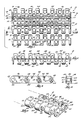
- FIG. 1 Illustrated in Fig. 1 is an open area conveyor chain assembly 10 embodying various features of the invention.
- the conveyor chain assembly 10 includes a plurality of integrally formed, generally elongated modules 12 which are pivotally connected to one another by a plurality of chain pins 14.
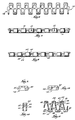
- Each of the modules 12 includes a plurality of forwardly extending link ends 16 which are spaced apart along the length of the module 12.
- Each of the forward link ends 16 includes (Fig. 5) an upper surface 18, each of which lie in the same plane, and a generally cylindrical barrel portion 20 which has opposite sides 22 and which defines a rounded, generally cylindrical and forwardly facing surface 24 which extends between the opposite sides 22 of the barrel portion 20 and which is adapted to be engaged by the drive tooth of a drive sprocket (not shown) driven by a drive shaft (not shown) or to be engaged by a similar drive mechanism.
- Each forward link end 16 also includes a bore 26 which extends axially through the link end 16 between the opposite sides 22 of the barrel portion 20. As shown in Fig. 1, the bore 26 has a diameter which is sufficiently large to house a portion of a chain pin 14.
- Each forward link end 16 also defines (Figs. 8 and 12) a rearwardly facing opening 28 which communicates with the bore 26 intermediate the opposite sides 22 of the barrel portion 20 and which (Fig. 1) exposes a portion of the chain pin 14.
- the opening 28 has a height which is approximately equal to the diameter of the chain pin 14 and a width which is approximately equal to the height.
- the forward link ends 16 define the opening 28 such that the chain pin 14 is exposed for visual inspection and cleaning from above and below.
- each forward link end 16 also includes a pair of forwardly facing, generally cylindrical surfaces 32 which are defined by the bore 26, which extend between one of the opposite sides 22 of the forward link end 16 and the rearwardly facing opening 28, and which are in opposed facing relation to the cylindrical surface 30.
- Each module 12 also includes (Figs. 2 and 3) a plurality of rearwardly extending link ends 34 which are spaced apart along the length of the module 12 and which are spaced from the forward link ends 16.
- Each of the rearward link ends 34 includes a (Fig. 5) substantially flat upper surface 36 and a generally cylindrical barrel portion 38 which has opposite sides 40 and which defines (Fig. 3) a rounded, generally cylindrical and rearwardly facing drive surface 42 which extends between the opposite sides 40 of the barrel portion 38 and which is adapted to be engaged by the drive tooth of a drive sprocket (not shown) or by a similar drive mechanism. Because the forwardly facing surface 16 and the rearwardly facing drive surface 42 are both adapted to be engaged by a drive mechanism, the conveyor assembly 10 can be driven bi-directionally.
- Each of the rearwardly extending link ends 34 also includes a bore 44 which extends axially between the opposite sides 40 of the barrel portion 38 and which houses a portion of one of the chain pins 14.
- Each rearward link end 34 also defines (Figs. 5 and 12) a forwardly facing opening 46 which communicates with the bore 44 intermediate the opposite sides 40 of the barrel portion 38 and which exposes the chain pin 14.
- the opening 28 has a height which is approximately equal to the diameter of the chain pin 14 and a width which is approximately equal to the height.
- the rearward link ends 34 define the opening 46 so that the chain pin 14 is exposed for visual inspection and cleaning from above and below.
- each rearward link end 34 defines (Figs. 5 and 11) a forwardly facing, generally cylindrical surface 48 which extends between the opposite sides 40 of the barrel portion 38. Because of the forwardly facing opening 46 in each rearward link end 34, the bore 44 also defines a pair of rearwardly facing, generally cylindrical surfaces 50 which extend between one of the opposite sides 40 of the barrel portion 38 and the opening 46, and which are in opposed facing relation to the forwardly facing surface 48.
- Each module 12 also includes (Fig. 2) a plurality of reach bars 52 which extend between respective forwardly and rearwardly extending link ends 16, 34.
- Each reach bar 52 has a lower edge 54, an upper edge 56 (Fig. 4) which, for reasons discussed below, is defined by an upwardly facing convex upper surface 58 having a generally bullet-shaped cross-sectional configuration when viewed in a plane generally perpendicular to the length of the reach bar 52, and a relatively vertical, thin web 60 which extends between the lower and upper edges 54, 56.
- each reach bar 52 extends between one of the opposite sides 22 of a forward link end 16 and one of the opposite sides 40 of a rearward link end 34. Because, as shown in Fig. 2, the forward and rearward link ends 16, 34 are spaced apart along the length of the module 12, and because the webs 60 are relatively thin, the reach bars 52 extend at an oblique angle relative to the length of the module 12.
- a pair of reach bars 52 extend from each of the link ends 16, 34 so that a reach bar 52 extends from each side of the rearwardly and forwardly facing openings 28, 46.
- a first reach bar 52 extends from one of the opposite sides 22, 40 of the barrel portions 20, 38 and a second reach bar 52 extends from the other opposite side 22, 40 of the barrel portions 20, 38 so that the openings 28, 46 extend between the pair of reach bars 52.
- each of the reach bars 52 extend at an oblique angle relative to the length of the module, and each of the pair of reach bars 52 extends at a divergent angle relative to the other of the pair of reach bars 52, so that each of the modules 12 comprises a plurality of the link ends 16, 34 and reach bars 52 configured in a zig-zag or crank-like arrangement.
- the conveyor assembly 10 also includes means 70 for retaining the chain pin 14 within the forwardly and rearwardly extending link ends 16, 34.
- the modules 12 include a first side link end 74 which limits axial movement of the chain pin in the direction of the one side 72.
- the first side link end 74 has a bore 76 which is axially aligned with the bores 26, 44 in the rearwardly and forwardly extending link ends 16, 34 and which has a blind end 77.
- a chain pin 14 extends into the bore 76 in the first side link end 74 but is prevented from moving toward the one side 72 (to the right in Fig. 1) of the conveyor assembly 10 by the blind end 77 of the bore 76.
- the modules 12 provide a second side link end 80 having a bore 82 which extends therethrough and which is aligned with the bores 26, 44.
- the means 70 for retaining the chain pin 14 also includes a selectively removable end cap 84 which engages the second side link end 80 and which substantially occupies the bore 82 so as to prevent movement of the chain pin 14 toward the opposite side 78 (to the left in Fig. 1) of the conveyor assembly 10.
- the conveyor assembly 10 can be assembled by placing rows of modules 12 in interdigited relation so that the forwardly and rearwardly extending link ends 16, 34 mesh and so that the bores 26, 34 align. A chain pin 14 is then slided through the second side link end 80 and into the bores 26, 44. The chain pin 14 is retained between the opposite sides 72, 78 of the conveyor assembly 10 by the first side link end 74 and by the end cap 84 in the second side link end 80.
- the chain pin 14 can be retained within the forwardly and rearwardly extending link ends 16, 34 by deforming the ends of the chain pin 14 once the chain pin 14 is housed by the bores 26, 44. If plastic chain pins are used, the ends of the chain pin 14 can be thermally deformed to form a head sufficiently large to prevent dislocation of the chain pin 14 from the bores 26, 44.
- tensile forces are transmitted between rows of modules 12 by the engagement of the link ends 16, 34 with the connecting chain pins 14.
- this transfer of tensile forces results in shearing forces acting on the chain pins 14 and on the forwardly and rearwardly extending link ends 16, 34.
- tensile forces acting between a first row of modules 12 and a second row of modules 12 will be transferred by the engagement of the chain pins 14 and the load-bearing, cylindrical surfaces 30, 48 which are defined by the bores 26, 34 and which extend across the entire width of the link ends 16, 34.
- the tensile forces act against the rearwardly facing cylindrical surface 30, and not against the pair of forwardly facing cylindrical surfaces 32. Because the load-bearing surface 30 extends across the entire width of the forwardly extending link end 16, the tensile forces are distributed across a greater surface area, which reduces stress in the forward link end 16.
- tensile forces act against the forwardly facing surface 48, and not the pair of rearwardly facing cylindrical surfaces 50. Because the forwardly facing surface 48 extends across the entire width of the rearward link end 34, the tensile forces are distributed across a greater surface area, which reduces stress in the rearward link end 34.
- a conveyor assembly 10 having a satisfactory overall tensile strength has been obtained by forming unitary modules 12 and chain pins 14 of acetal resin, however, any moldable, high-strength plastic can be successfully used.
- An overall tensile strength of approximately 952.6 Kg (2100 pounds) for a conveyor assembly having a 0 ⁇ 3048 m (12 inch) width can be realized by using these materials.
- Substitution of steel connecting pins for the plastic chain pins can increase the realized strength of the conveyor assembly 10 to approximately 1950.5 Kg (4300 pounds).
- Each module 12 also includes (Fig. 1) a support rib 90 which extends between the upper edges 56 of the reach bars 52 intermediate the link ends 16, 34 and which extends generally parallel to the chain pins 14 and along the length of the module 12.
- Each support rib 90 (Fig. 3) has an upper edge 92 and a lower surface 94 which is spaced from the lower edge 54 of the reach bars 52.
- the upper edge 92 of the support rib 90 is defined by an upwardly facing, convex upper surface 95.
- the upper surface 95 of the support rib 90 has a generally bullet-shaped configuration and is substantially equidistant from the cylindrical surfaces 24 and 42.
- the upper surfaces 18, 36 of the forwardly and rearwardly extending link ends 16, 34, the upper surface 58 of the reach bars 52, and the upper surface 95 of the support rib 90 of the plurality of modules 12 provide (Fig. 3) an article support surface 96.
- the link ends 16, 34, the reach bars 52 and the support rib 90 also define therebetween a plurality of openings 98 adapted to provide for a free flow of fluid through the modules 12 in a direction generally perpendicular to the support surface 96.
- the openings 98 are adapted to provide for free flow of air through the conveyor assembly 10 for the cooling or drying of articles placed thereon.
- the aerodynamic, bullet-shaped configuration of the respective upper surfaces 95, 58 of the support rib 90 and the reach bars 52 minimize the amount of surface contact between the conveyor assembly 10 and articles placed thereon. Minimization of the surface contact between the conveyor assembly 10 and articles placed thereon can minimize the amount of flash-freezing or sticking which can occur between the article and the conveyor assembly 10 and can ease cleaning of the conveyor assembly 10.
- the bullet-shaped, upper surfaces 58, 95 of the reach bars 52 and the support rib 90 also reduce turbulence in the flow of fluid passing through the conveyor assembly 10, and thereby minimize resistance to the passage of the flow therethrough.
- the conveyor assembly can be constructed to have a relatively small pitch.
- the provision of a relatively small pitch allows the conveyor assembly to be driven by a relatively small drive mechanism and facilitates the transfer of articles to and from the assembly. More particularly, because the conveyor assembly is adapted to be driven by the teeth of a drive sprocket driven by a drive shaft, the provision of a conveyor assembly having a relatively small pitch allows the pitch of the drive sprocket, and therefore the respective diameters of the drive sprocket and drive shaft to be reduced. By reducing the size of the drive mechanism, the overall size of the conveyor assembly is also reduced.
- the conveyor assembly thus provides a high-strength conveyor which has a relatively large amount of open area, a relatively small pitch and which can carry relatively small articles thereon.
Landscapes
- Engineering & Computer Science (AREA)
- Mechanical Engineering (AREA)
- Chain Conveyers (AREA)
- Structure Of Belt Conveyors (AREA)
Applications Claiming Priority (2)
| Application Number | Priority Date | Filing Date | Title |
|---|---|---|---|
| US60389290A | 1990-10-25 | 1990-10-25 | |
| US603892 | 1990-10-25 |
Publications (2)
| Publication Number | Publication Date |
|---|---|
| EP0482729A1 EP0482729A1 (en) | 1992-04-29 |
| EP0482729B1 true EP0482729B1 (en) | 1995-07-19 |
Family
ID=24417348
Family Applications (1)
| Application Number | Title | Priority Date | Filing Date |
|---|---|---|---|
| EP91300378A Expired - Lifetime EP0482729B1 (en) | 1990-10-25 | 1991-01-17 | Conveyor chain assembly |
Country Status (8)
| Country | Link |
|---|---|
| EP (1) | EP0482729B1 (da) |
| JP (1) | JPH0524620A (da) |
| KR (1) | KR100203212B1 (da) |
| AT (1) | ATE125233T1 (da) |
| CA (1) | CA2035271C (da) |
| DE (1) | DE69111369T2 (da) |
| DK (1) | DK0482729T3 (da) |
| ES (1) | ES2074653T3 (da) |
Families Citing this family (2)
| Publication number | Priority date | Publication date | Assignee | Title |
|---|---|---|---|---|
| US5678683A (en) * | 1996-02-05 | 1997-10-21 | Rexnord Corporation | Conveyor chain with sealed plug hinge pin retention system |
| JP4298741B2 (ja) | 2006-01-17 | 2009-07-22 | ナックフィーディング株式会社 | 振動型搬送装置 |
Family Cites Families (7)
| Publication number | Priority date | Publication date | Assignee | Title |
|---|---|---|---|---|
| US3631980A (en) * | 1969-08-04 | 1972-01-04 | Frank Hamachek Machine Co | Open mesh belt cleaner |
| GB1575729A (en) * | 1978-05-26 | 1980-09-24 | Umec Boydell Ltd | Conveyor belts |
| USRE30341E (en) * | 1978-06-22 | 1980-07-22 | The Laitram Corporation | Conveyor drive |
| IE50415B1 (en) * | 1980-01-15 | 1986-04-16 | Umec Boydell Belting Ltd | Conveyor belt of the honeycomb type |
| US4846339A (en) * | 1987-03-11 | 1989-07-11 | Ashworth Bros., Inc. | Flat wire conveyor with differential pitch |
| US4972942A (en) * | 1988-07-18 | 1990-11-27 | Faulkner William G | Conveyor belt |
| DK162348C (da) * | 1989-07-20 | 1992-03-09 | Joergen Draebel | Kaedeled til en sideboejelig transportkaede |
-
1991
- 1991-01-17 DE DE69111369T patent/DE69111369T2/de not_active Expired - Lifetime
- 1991-01-17 DK DK91300378.6T patent/DK0482729T3/da active
- 1991-01-17 EP EP91300378A patent/EP0482729B1/en not_active Expired - Lifetime
- 1991-01-17 ES ES91300378T patent/ES2074653T3/es not_active Expired - Lifetime
- 1991-01-17 AT AT91300378T patent/ATE125233T1/de not_active IP Right Cessation
- 1991-01-30 CA CA002035271A patent/CA2035271C/en not_active Expired - Lifetime
- 1991-03-14 JP JP3127005A patent/JPH0524620A/ja active Pending
- 1991-03-30 KR KR1019910005085A patent/KR100203212B1/ko not_active Expired - Lifetime
Also Published As
| Publication number | Publication date |
|---|---|
| ES2074653T3 (es) | 1995-09-16 |
| KR100203212B1 (ko) | 1999-06-15 |
| JPH0524620A (ja) | 1993-02-02 |
| DE69111369T2 (de) | 1996-03-07 |
| EP0482729A1 (en) | 1992-04-29 |
| DE69111369D1 (de) | 1995-08-24 |
| KR920007903A (ko) | 1992-05-27 |
| CA2035271A1 (en) | 1992-04-26 |
| ATE125233T1 (de) | 1995-08-15 |
| CA2035271C (en) | 2001-04-17 |
| DK0482729T3 (da) | 1995-09-11 |
Similar Documents
| Publication | Publication Date | Title |
|---|---|---|
| US5253749A (en) | Open area conveyor assembly | |
| US5706934A (en) | Modular solid top plastic conveyor belt | |
| US4556142A (en) | Lightweight modular conveyor belt | |
| US6467610B1 (en) | Modular conveyor belts with pin-retained attachments | |
| US5419428A (en) | Plastic conveyor belt with integral sideplate | |
| US5123524A (en) | Modular center drive conveyor belt | |
| US4729469A (en) | Flat top conveyor belt | |
| US6766901B2 (en) | Snap-on side guards | |
| US4865183A (en) | Wide chain conveyor sprocket drive | |
| US4688670A (en) | Flat top conveyor belt | |
| US4821872A (en) | Lightweight modular conveyor belt | |
| CA1270788A (en) | Chain link for a product capturing chain | |
| US4858751A (en) | Wide chain conveyor assembly | |
| EP0482729B1 (en) | Conveyor chain assembly | |
| US5024321A (en) | Modular center drive conveyor belt | |
| US4941568A (en) | Accurate tracking center driven open area belt | |
| EP1270454A1 (en) | Flush grid belt module | |
| EP0144455A1 (en) | Flat top conveyor belt | |
| US4971191A (en) | Accurate tracking center driven open area belt | |
| EP0207460A1 (en) | Lightweight modular conveyor belt | |
| AU639139B2 (en) | Straight running conveyor chain for use with fingered transfer plate | |
| JP3626817B2 (ja) | コンベアベルト構成単位片とこれを用いて形成したコンベアベルト | |
| CA1228045A (en) | Flat top conveyor belt |
Legal Events
| Date | Code | Title | Description |
|---|---|---|---|
| PUAI | Public reference made under article 153(3) epc to a published international application that has entered the european phase |
Free format text: ORIGINAL CODE: 0009012 |
|
| AK | Designated contracting states |
Kind code of ref document: A1 Designated state(s): AT BE CH DE DK ES FR GB GR IT LI LU NL SE |
|
| 17P | Request for examination filed |
Effective date: 19920827 |
|
| 17Q | First examination report despatched |
Effective date: 19940415 |
|
| ITF | It: translation for a ep patent filed | ||
| GRAA | (expected) grant |
Free format text: ORIGINAL CODE: 0009210 |
|
| AK | Designated contracting states |
Kind code of ref document: B1 Designated state(s): AT BE CH DE DK ES FR GB GR IT LI LU NL SE |
|
| PG25 | Lapsed in a contracting state [announced via postgrant information from national office to epo] |
Ref country code: BE Effective date: 19950719 Ref country code: LI Effective date: 19950719 Ref country code: CH Effective date: 19950719 Ref country code: GR Free format text: LAPSE BECAUSE OF FAILURE TO SUBMIT A TRANSLATION OF THE DESCRIPTION OR TO PAY THE FEE WITHIN THE PRESCRIBED TIME-LIMIT Effective date: 19950719 Ref country code: AT Effective date: 19950719 |
|
| REF | Corresponds to: |
Ref document number: 125233 Country of ref document: AT Date of ref document: 19950815 Kind code of ref document: T |
|
| REF | Corresponds to: |
Ref document number: 69111369 Country of ref document: DE Date of ref document: 19950824 |
|
| REG | Reference to a national code |
Ref country code: DK Ref legal event code: T3 |
|
| REG | Reference to a national code |
Ref country code: ES Ref legal event code: FG2A Ref document number: 2074653 Country of ref document: ES Kind code of ref document: T3 |
|
| ET | Fr: translation filed | ||
| PG25 | Lapsed in a contracting state [announced via postgrant information from national office to epo] |
Ref country code: LU Free format text: LAPSE BECAUSE OF NON-PAYMENT OF DUE FEES Effective date: 19960131 |
|
| PLBE | No opposition filed within time limit |
Free format text: ORIGINAL CODE: 0009261 |
|
| STAA | Information on the status of an ep patent application or granted ep patent |
Free format text: STATUS: NO OPPOSITION FILED WITHIN TIME LIMIT |
|
| 26N | No opposition filed | ||
| REG | Reference to a national code |
Ref country code: GB Ref legal event code: IF02 |
|
| PG25 | Lapsed in a contracting state [announced via postgrant information from national office to epo] |
Ref country code: IT Free format text: LAPSE BECAUSE OF NON-PAYMENT OF DUE FEES Effective date: 20080117 |
|
| PGFP | Annual fee paid to national office [announced via postgrant information from national office to epo] |
Ref country code: IT Payment date: 20090129 Year of fee payment: 18 |
|
| PGFP | Annual fee paid to national office [announced via postgrant information from national office to epo] |
Ref country code: DK Payment date: 20100126 Year of fee payment: 20 Ref country code: ES Payment date: 20100126 Year of fee payment: 20 |
|
| PGFP | Annual fee paid to national office [announced via postgrant information from national office to epo] |
Ref country code: FR Payment date: 20100205 Year of fee payment: 20 |
|
| PGFP | Annual fee paid to national office [announced via postgrant information from national office to epo] |
Ref country code: GB Payment date: 20100125 Year of fee payment: 20 Ref country code: DE Payment date: 20100127 Year of fee payment: 20 |
|
| PGFP | Annual fee paid to national office [announced via postgrant information from national office to epo] |
Ref country code: NL Payment date: 20100124 Year of fee payment: 20 |
|
| PGFP | Annual fee paid to national office [announced via postgrant information from national office to epo] |
Ref country code: SE Payment date: 20100127 Year of fee payment: 20 |
|
| REG | Reference to a national code |
Ref country code: NL Ref legal event code: V4 Effective date: 20110117 |
|
| REG | Reference to a national code |
Ref country code: DK Ref legal event code: EUP |
|
| REG | Reference to a national code |
Ref country code: GB Ref legal event code: PE20 Expiry date: 20110116 |
|
| REG | Reference to a national code |
Ref country code: ES Ref legal event code: FD2A Effective date: 20110302 |
|
| PG25 | Lapsed in a contracting state [announced via postgrant information from national office to epo] |
Ref country code: NL Free format text: LAPSE BECAUSE OF EXPIRATION OF PROTECTION Effective date: 20110117 |
|
| PG25 | Lapsed in a contracting state [announced via postgrant information from national office to epo] |
Ref country code: GB Free format text: LAPSE BECAUSE OF EXPIRATION OF PROTECTION Effective date: 20110116 Ref country code: ES Free format text: LAPSE BECAUSE OF EXPIRATION OF PROTECTION Effective date: 20110118 |
|
| PG25 | Lapsed in a contracting state [announced via postgrant information from national office to epo] |
Ref country code: DE Free format text: LAPSE BECAUSE OF EXPIRATION OF PROTECTION Effective date: 20110117 |