EP0482738A1 - Procédé et appareil frigorifique mécanique et à absorption combinée - Google Patents
Procédé et appareil frigorifique mécanique et à absorption combinée Download PDFInfo
- Publication number
- EP0482738A1 EP0482738A1 EP91305609A EP91305609A EP0482738A1 EP 0482738 A1 EP0482738 A1 EP 0482738A1 EP 91305609 A EP91305609 A EP 91305609A EP 91305609 A EP91305609 A EP 91305609A EP 0482738 A1 EP0482738 A1 EP 0482738A1
- Authority
- EP
- European Patent Office
- Prior art keywords
- cooling
- during
- vessel
- mechanical
- refrigeration
- Prior art date
- Legal status (The legal status is an assumption and is not a legal conclusion. Google has not performed a legal analysis and makes no representation as to the accuracy of the status listed.)
- Withdrawn
Links
- 238000005057 refrigeration Methods 0.000 title claims abstract description 123
- 238000010521 absorption reaction Methods 0.000 title claims abstract description 58
- 238000000034 method Methods 0.000 title claims abstract description 22
- 238000001816 cooling Methods 0.000 claims abstract description 81
- 239000003085 diluting agent Substances 0.000 claims abstract description 58
- 230000002745 absorbent Effects 0.000 claims abstract description 54
- 239000002250 absorbent Substances 0.000 claims abstract description 54
- 238000003860 storage Methods 0.000 claims abstract description 52
- 239000007788 liquid Substances 0.000 claims abstract description 42
- 239000006096 absorbing agent Substances 0.000 claims description 40
- 239000012530 fluid Substances 0.000 claims description 32
- 239000003507 refrigerant Substances 0.000 claims description 22
- 239000007921 spray Substances 0.000 claims description 18
- 230000004087 circulation Effects 0.000 claims description 9
- 238000010438 heat treatment Methods 0.000 claims description 9
- 238000004378 air conditioning Methods 0.000 abstract description 7
- 239000012141 concentrate Substances 0.000 abstract 1
- 239000000243 solution Substances 0.000 description 54
- 230000009102 absorption Effects 0.000 description 51
- XLYOFNOQVPJJNP-UHFFFAOYSA-N water Substances O XLYOFNOQVPJJNP-UHFFFAOYSA-N 0.000 description 21
- 239000007789 gas Substances 0.000 description 12
- AMXOYNBUYSYVKV-UHFFFAOYSA-M lithium bromide Chemical compound [Li+].[Br-] AMXOYNBUYSYVKV-UHFFFAOYSA-M 0.000 description 12
- 238000009434 installation Methods 0.000 description 10
- 239000006193 liquid solution Substances 0.000 description 7
- 230000006835 compression Effects 0.000 description 5
- 238000007906 compression Methods 0.000 description 5
- QSHDDOUJBYECFT-UHFFFAOYSA-N mercury Chemical compound [Hg] QSHDDOUJBYECFT-UHFFFAOYSA-N 0.000 description 5
- 229910052753 mercury Inorganic materials 0.000 description 5
- 230000008016 vaporization Effects 0.000 description 5
- QGZKDVFQNNGYKY-UHFFFAOYSA-N Ammonia Chemical compound N QGZKDVFQNNGYKY-UHFFFAOYSA-N 0.000 description 4
- 238000009833 condensation Methods 0.000 description 4
- 230000005494 condensation Effects 0.000 description 4
- 230000008569 process Effects 0.000 description 4
- 239000013589 supplement Substances 0.000 description 4
- HEMHJVSKTPXQMS-UHFFFAOYSA-M Sodium hydroxide Chemical compound [OH-].[Na+] HEMHJVSKTPXQMS-UHFFFAOYSA-M 0.000 description 3
- 238000013461 design Methods 0.000 description 3
- 239000000446 fuel Substances 0.000 description 3
- 238000009834 vaporization Methods 0.000 description 3
- 229910021529 ammonia Inorganic materials 0.000 description 2
- 239000007864 aqueous solution Substances 0.000 description 2
- 238000009835 boiling Methods 0.000 description 2
- 238000007865 diluting Methods 0.000 description 2
- 230000007613 environmental effect Effects 0.000 description 2
- 230000002349 favourable effect Effects 0.000 description 2
- 229930195733 hydrocarbon Natural products 0.000 description 2
- 150000002430 hydrocarbons Chemical class 0.000 description 2
- 238000012986 modification Methods 0.000 description 2
- 230000004048 modification Effects 0.000 description 2
- 230000001105 regulatory effect Effects 0.000 description 2
- 238000009420 retrofitting Methods 0.000 description 2
- 239000004215 Carbon black (E152) Substances 0.000 description 1
- 238000009825 accumulation Methods 0.000 description 1
- AXCZMVOFGPJBDE-UHFFFAOYSA-L calcium dihydroxide Chemical compound [OH-].[OH-].[Ca+2] AXCZMVOFGPJBDE-UHFFFAOYSA-L 0.000 description 1
- 239000000920 calcium hydroxide Substances 0.000 description 1
- 229910001861 calcium hydroxide Inorganic materials 0.000 description 1
- 230000001276 controlling effect Effects 0.000 description 1
- 239000012809 cooling fluid Substances 0.000 description 1
- 230000001419 dependent effect Effects 0.000 description 1
- 230000000694 effects Effects 0.000 description 1
- 230000005611 electricity Effects 0.000 description 1
- 238000001704 evaporation Methods 0.000 description 1
- 230000008020 evaporation Effects 0.000 description 1
- 238000000605 extraction Methods 0.000 description 1
- 238000002347 injection Methods 0.000 description 1
- 239000007924 injection Substances 0.000 description 1
- 238000012432 intermediate storage Methods 0.000 description 1
- 231100000053 low toxicity Toxicity 0.000 description 1
- 238000004519 manufacturing process Methods 0.000 description 1
- 239000002609 medium Substances 0.000 description 1
- 238000005192 partition Methods 0.000 description 1
- 238000012545 processing Methods 0.000 description 1
- 230000009103 reabsorption Effects 0.000 description 1
- 238000000926 separation method Methods 0.000 description 1
- 238000001179 sorption measurement Methods 0.000 description 1
- 238000012546 transfer Methods 0.000 description 1
- 238000013022 venting Methods 0.000 description 1
- 238000010792 warming Methods 0.000 description 1
- 239000002918 waste heat Substances 0.000 description 1
- 238000009736 wetting Methods 0.000 description 1
Images


Classifications
-
- F—MECHANICAL ENGINEERING; LIGHTING; HEATING; WEAPONS; BLASTING
- F25—REFRIGERATION OR COOLING; COMBINED HEATING AND REFRIGERATION SYSTEMS; HEAT PUMP SYSTEMS; MANUFACTURE OR STORAGE OF ICE; LIQUEFACTION SOLIDIFICATION OF GASES
- F25B—REFRIGERATION MACHINES, PLANTS OR SYSTEMS; COMBINED HEATING AND REFRIGERATION SYSTEMS; HEAT PUMP SYSTEMS
- F25B25/00—Machines, plants or systems, using a combination of modes of operation covered by two or more of the groups F25B1/00 - F25B23/00
- F25B25/02—Compression-sorption machines, plants, or systems
-
- F—MECHANICAL ENGINEERING; LIGHTING; HEATING; WEAPONS; BLASTING
- F25—REFRIGERATION OR COOLING; COMBINED HEATING AND REFRIGERATION SYSTEMS; HEAT PUMP SYSTEMS; MANUFACTURE OR STORAGE OF ICE; LIQUEFACTION SOLIDIFICATION OF GASES
- F25B—REFRIGERATION MACHINES, PLANTS OR SYSTEMS; COMBINED HEATING AND REFRIGERATION SYSTEMS; HEAT PUMP SYSTEMS
- F25B15/00—Sorption machines, plants or systems, operating continuously, e.g. absorption type
- F25B15/02—Sorption machines, plants or systems, operating continuously, e.g. absorption type without inert gas
- F25B15/06—Sorption machines, plants or systems, operating continuously, e.g. absorption type without inert gas the refrigerant being water vapour evaporated from a salt solution, e.g. lithium bromide
-
- Y—GENERAL TAGGING OF NEW TECHNOLOGICAL DEVELOPMENTS; GENERAL TAGGING OF CROSS-SECTIONAL TECHNOLOGIES SPANNING OVER SEVERAL SECTIONS OF THE IPC; TECHNICAL SUBJECTS COVERED BY FORMER USPC CROSS-REFERENCE ART COLLECTIONS [XRACs] AND DIGESTS
- Y02—TECHNOLOGIES OR APPLICATIONS FOR MITIGATION OR ADAPTATION AGAINST CLIMATE CHANGE
- Y02A—TECHNOLOGIES FOR ADAPTATION TO CLIMATE CHANGE
- Y02A30/00—Adapting or protecting infrastructure or their operation
- Y02A30/27—Relating to heating, ventilation or air conditioning [HVAC] technologies
-
- Y—GENERAL TAGGING OF NEW TECHNOLOGICAL DEVELOPMENTS; GENERAL TAGGING OF CROSS-SECTIONAL TECHNOLOGIES SPANNING OVER SEVERAL SECTIONS OF THE IPC; TECHNICAL SUBJECTS COVERED BY FORMER USPC CROSS-REFERENCE ART COLLECTIONS [XRACs] AND DIGESTS
- Y02—TECHNOLOGIES OR APPLICATIONS FOR MITIGATION OR ADAPTATION AGAINST CLIMATE CHANGE
- Y02B—CLIMATE CHANGE MITIGATION TECHNOLOGIES RELATED TO BUILDINGS, e.g. HOUSING, HOUSE APPLIANCES OR RELATED END-USER APPLICATIONS
- Y02B30/00—Energy efficient heating, ventilation or air conditioning [HVAC]
- Y02B30/62—Absorption based systems
Definitions
- the present invention relates to refrigeration and more specifically deals with an improved method and apparatus combining an absorption refrigeration system with a mechanical refrigeration system to supplement chilling capacity and to store thermal energy.
- Absorption refrigeration systems which are driven by heat energy, have been long known and indeed predate mechanical expansion refrigeration; but the latter has become more prevalent in existing installations due to abundant and inexpensive electrical energy and the discovery and commercial production of fluorinated hydrocarbon refrigerant gases.
- increasing costs for electrical energy, especially during high demand portions of a calendar day, and environmental concerns associated with fluorinated hydrocarbons are creating opportunities for absorption refrigeration.
- absorption herein is to be interpreted broadly so as to embrace both absorption and adsorption phenomena.
- a liquid solution such as lithium bromide in water
- a diluent component water
- the concentrated solution is delivered to a second absorber phase where it absorbs or reabsorbs that component so as to become diluted.
- the diluent component such as water
- the load such as refrigerated or cooled space
- the present invention provides a method for combining absorption refrigeration and mechanical refrigeration systems to cool a refrigeration medium for circulation to a cooling load during a cooling cycle and to store cooling energy during a storage cycle, said method comprising:
- the present invention provides a combined refrigeration system including an absorption refrigeration system and a mechanical expansion refrigeration system to cool a refrigeration medium for circulation to a cooling load during a cooling cycle and to store cooling energy during a storage cycle, said combined system comprising:
- the present invention involves the combination of an absorption refrigeration system with a mechanical expansion refrigeration system and the addition of adequate storage for both concentrated and diluted liquid absorbent solutions and cold liquid diluent so as to enable the concentrator phase and the evaporator phase of the absorption system to be operable at dissimilar rates and/or time periods and thereby be available to supplement the cooling capacity of the mechanical system during peak demand.
- the absorption system is sized to provide approximately one-half of the cooling capacity needed to serve the air conditioning load and the evaporator phase output is connected, preferably in series, with the mechanical system during the cooling cycle (usually during a workday) and the concentrator phase is connected with the mechanical system during a storage cycle (usually during night time when electrical energy costs are relatively low).
- both concentrator and evaporator phases of the absorption system are operated at relatively equal pressure whereby the diluent saturation temperatures are substantially equal and temperature variation of the absorbent solution between phases is minimized.
- this equalization increases the efficiency of the absorption system and eliminates the need for a costly and troublesome liquid solution heat interchanger as has heretofore been used with conventional absorption systems.
- the equalization which this invention makes possible works to minimize the solution concentrations and temperatures, a combination which will reduce the corrosive characteristics of the absorbent solution.
- absorption refrigeration involves the steps of concentrating an absorption refrigerant liquid solution, such as an aqueous solution of lithium bromide, by heating a first internal liquid stream of a relatively weak or diluted solution within a first concentrator phase containing generator and condenser functions to distill a diluent vapor (generator function) and therein condensing (condenser function) the vapor by cooling, thereby producing internal liquid streams of relatively concentrated or strong absorbent solution (in the generator) and cold diluent (in the condenser). Both of these liquid streams are utilized in a second evaporator phase where the cold liquid diluent is used for chilling an external refrigeration medium that is circulated to a cooling load.
- an absorption refrigerant liquid solution such as an aqueous solution of lithium bromide
- Aqueous solutions of lithium bromide are preferred because of favorable cost and environmental considerations, such as low toxicity.
- other diluent/absorbent pairs are known to satisfactorily perform in absorption refrigeration systems such as ammonia/water, water/sodium hydroxide, and water/calcium hydroxide, and may be used in the present method and apparatus.
- absorption refrigeration tends to be an economical choice where sources of heat and cold are relatively inexpensive.
- mechanical expansion refrigeration systems which provide cooling through the vaporization of an internal refrigerant gas also involve compression of the gas and the extraction of the heat of condensation and the heat of compression before the expansion and vaporization cycle; and compression requires either a reciprocating or a centrifugal compressor which must be energized by motive power, from a motor or engine.
- mechanical refrigeration tends to be the more economical choice where motors and engines and fuels to run them, especially electricity, are plentiful and relatively inexpensive.
- both systems produce relatively hot and relatively cold external or output media, the hot media normally being circulated to a heat ejector (such as a cooling tower), and the cold media normally being circulated to an air conditioning or other cooling load.
- a heat ejector such as a cooling tower
- the cold media normally being circulated to an air conditioning or other cooling load.
- the usual mechanical systems depend on essentially continuous flow of the expandable refrigerant gas during load cycles and do not lend themselves to safe direct storage of cold thermal energy; whereas it has been found that an absorption system can be designed to directly store cold thermal energy by providing for the accumulation of excess quantities of internal strong absorbent solution and internal diluent liquid produced in the concentrator phase.
- the typical mechanical system comprises a closed fluid circuit with a compressor, either reciprocable or centrifugal, which compresses a refrigerant gas, a heat extractor to discharge heats of condensation and compression and a vaporizing section where the fluid boils at low temperature to consume heat. It has also now been found that mechanical and absorption systems may be combined so as to process a common or single external cold medium during a chilling or air conditioning cycle and the mechanical system output provides the total input energy to the absorption system during a thermal storage cycle.
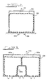
- the absorption system of this present method provides for storing at least portions of the separate strong solution and diluent liquid streams in first and second zones 40, 50, respectively, as shown in FIGURE 1 against demand in a second evaporator phase containing evaporator and absorber functions where the liquid diluent is used for chilling a refrigeration heat exchanger 90 connected to process an external refrigeration medium for an air conditioning or refrigeration load, or the like.
- Heat transferred to the cold liquid diluent during the chilling step will cause evaporation of some diluent which is thereby available for diluting a second stream of strong liquid solution (absorber function) removed from the first zone and introduced within the absorber phase, thereby producing a second liquid stream of diluted or weak solution at a rate dependent upon controlling the flow of the second liquid stream of strong solution from the first zone.
- the absorption cycle is closed by storing at least a portion of the second weak liquid solution stream in a third zone 70 and subsequently withdrawing the first liquid stream of relatively weak solution therefrom and introducing same to the first concentrator phase at a rate determined by the capacity of the concentrator phase, and only during intervals when replenishing the liquids stored in the first and second zones 40 and 50.
- mercury absolute which provides for a water vapor saturation temperature (condensation temperature) of about 35 ° F (1.7 °C) and relatively low solution boiling temperature; whereas the operating pressure normally found in prior absorption refrigeration concentrators which reject heat to the atmosphere, is in the range of 3 inch (76.2 cm.) mercury, absolute, resulting in water vapor saturation temperatures of about 115" F (46.1 ° c) and a weak solution boiling point of about 220 F (104.4 ° C).
- the diluent vapor e.g. water vapor
- the liquid diluent condensate may be delivered at that temperature to the second storage zone.
- the liquid water diluent is also available at about 35 ° F (1.7°C) for use as a chilling medium in the evaporator phase where it may be applied to chill a refrigeration heat exchanger containing a fluid refrigeration medium from an air conditioner, or the like.
- the cold liquid diluent is introduced into the evaporator phase at a rate sufficient to meet the design demand of the refrigeration medium or load. It is often advantageous to apply and recirculate an excess of the cold liquid diluent to the refrigeration medium heat exchanger 90 to insure adequate wetting of the heat transfer surface.
- the heat from the refrigeration medium heat exchanger vaporizes a portion of the diluent; and that vapor is then available to be absorbed in the second liquid stream of warm concentrated absorbent solution which is injected into the absorber phase at a rate adequate to absorb the diluent vapor generated at the refrigeration heat exchanger.
- the injected absorbent solution and diluent vapor are preferably cooled a few degrees by a second heat exchanger 92 within the evaporator phase to remove the heat from the exothermic absorption process.
- the amount of cooling is regulated, along with the injection rate for concentrated absorbent solution, so as to maintain the pressure within the evaporator phase at an optimum level (0.2 inch mercury, absolute, in a preferred embodiment).
- the resultant cool diluted and relatively weak liquid absorbent solution is withdrawn to the third storage zone 70 where it is held against demand in the concentrator phase. It is intended that the concentrator phase be operated at near optimum design capacity for periods of time that may or may not be coincident with the operating cycle of the absorber phase.
- heating of the first stream of relatively weak liquid absorbent solution within the first concentrator phase of an absorption system may be efficiently achieved by heat liberated from a condenser stage of an electric powered heat pump; and the resultant diluent vapor is condensed by the heat pump evaporator, thereby conserving the latent heat of condensation of the diluent and reinjecting it into the concentration process.
- the concentrator phase chamber contains both the condenser 12 and evaporator 14 stage heat exchangers of a mechanical heat pump wherein the heat pump compressor 18, driven by a power means such as, an electric motor 20 or fuel fired engine, is conveniently located outside the concentrator chamber.
- the absorption refrigeration system supplement the cooling capacity of a mechanical expansion refrigeration system and provide a thermal storage reserve usable during periods of peak cooling demand to reduce the energy required by the mechanical system.
- the mechanical system may be alternately connected to the absorber concentrator to both supply the thermal energy necessary for vaporizing diluent from the weak absorber solution and also condensing the diluent.
- This is accompanied by substantially continuously operating the mechanical system and alternately first operating the absorber system evaporator phase and combining the cooling capacity of the mechanical gas expansion section with the cooling capacity of the evaporator section of the absorber system to chill a refrigeration medium during a chilling cycle (during which time the heat outputs of both the absorber and the mechanical compression heat extractor are combined to a heat ejector and the absorber produces quantities of weak absorber solution) and second operating the absorber system concentrator phase while connecting the cooling capacity of the mechanical gas expansion section to the condenser section and connecting the heat extractor of the mechanical system to the generator section of the absorption system to drive the concentrator phase to produce and store quantities of both strong absorbent solution and cold diluent.
- FIGURE 1 A basic absorption and storage system of apparatus is schematically illustrated in FIGURE 1 wherein a concentrator vessel 10, such as closed cylindrical tank, contains a heat pump circuit comprising a condenser coil 12 in a lower (generator) section of the vessel and an evaporator coil 14 in an upper (condenser) section of the vessel.
- the coils 12 and 14 are interconnected by a refrigerant expansion valve 16 and each coil is connected in the usual manner to a compressor 18 located outside the vessel.
- the compressor is driven by an electric motor 20.
- an auxiliary exterior heat exchanger not shown
- the concentrator vessel 10 also contains a first diluent collection pan 30, located directly beneath the evaporator coil 14, and a first absorbent solution spray header 32, located directly above the condenser coil 12.
- An absorbent solution sump 34 is located in the vessel 10 beneath the condenser coil 12.
- a first reservoir 40 is connected to the sump 34 of concentrator vessel 10 by a pipe 42, pump 44 and a check valve 46; and a second reservoir 50 is connected to the first diluent collection pan 30 by a pipe 52, pump 54 and a check valve 48.
- the second reservoir 50 is also connected to a diluent spray header 56 through a variable flow control valve 58.
- the diluent spray header 56 is located within one (evaporator) section, usually an upper section, of an evaporator/absorber vessel 60.
- a second absorbent solution spray header 62 located in an adjacent, usually lower, (absorber) section of the vessel 60 is connected to the first reservoir 40 through another variable flow control valve 64.
- a second absorbent solution sump 66 is located in the evaporator/absorber vessel 60 beneath the second spray header 62 and is connected by pipe 68 to a third reservoir 70 which, in turn, is connected through a variable flow control valve 72 to the first absorber solution spray header 32.
- a pump 74 and a check valve 76 are connected in pipe 68 between the sump 66 and third reservoir 70.
- a second diluent collection pan 80 is positioned within evaporator/absorber vessel 60 below the diluent spray header 56 and is connected by a pipe 82 and pump 84 to recirculate diluent directly to the spray header 56.
- Heat exchanger coil 90 is located between the first diluent spray header 56 and collector pan 80 and circulates refrigeration medium from a cooling load such as an office air conditioning system, or the like (not shown).
- the heat exchanger 92 is positioned between the second absorber solution spray header 62 and the sump 66 and circulates fluid from a heat rejector such as a cooling tower (not shown).
- First, second and third reservoirs 40, 50 and 70 respectively, have their outer shells vented to atmosphere (not shown in FIGURE 1) in the valve and pump arrangement described. Alternately, they may be vented to the concentrator vessel or to the evaporator/absorber vessel, but they must be elevated above the vessel to which they feed liquid.
- the vessel 10 is maintained at 0.2 inch (5.1 cm.) Hg. absolute and the heat pump compressor 18 and coils 12 and 14 are sized and operated to deliver superheated refrigerant gas at about 145 ° F (62.8 °C) to the condenser coil 12, discharge refrigerant liquid at about 127 ° F (52.8 C) to the expansion valve 16 and to return refrigerant gas at about 30 ° F (-1.1 ° C) to the compressor inlet.
- Water vapor within the concentrator vessel will condense on the evaporator coil 14 and accumulate in the first collector pan 30 at about 35 ° F (1.7 ° C) from whence it is stored in the second reservoir 50 so as to be available on demand in the evaporator/absorber vessel 60.
- the liquid water sprayed across the refrigeration heat exchanger 90 will remain at about 35 ° F (1.7°C) yet the available heat of vaporization will be adequate to chill refrigerant in the heat exchanger 90 from an inlet temperature of about 50 ° (10°C) to an outlet temperature of about 40 F F (4.4 °C).
- the water vapor is reabsorbed in the strong lithium bromide solution drawn from the first reservoir 40 thereby diluting the solution to about 57t% which is then returned to the third reservoir 70.
- the solution is cooled by the rejection heat exchanger 92 to about 95 ° F (35 C) so as to maintain the vessel pressure at about 0.2 inch (5.1 cm.) Hg.
- the rejection heat exchanger 92 may be sized so that 85 ° F (29.4 °C) water from a cooling tower, or the like, is adequate to cool the diluted absorbent solution.
- each of the three separate reservoirs 40, 50 and 70 shown in the system of FIGURE 1, when vented to the atmosphere, may be construed as shown in FIGURE 2 to comprise an expandable bladder 100 within a rigid vessel 102 and separate inlet and outlet connectors 104, 106 and a vent 110.
- Atmosphere venting of the reservoir vessels provides a relatively constant pressure for feeding the control valves, and the bladders provide both a movable partition for fluid volume changes and means for preventing air and/or moisture absorption. It is also possible to combine the three reservoirs by utilizing three separate expandable bladders 100a, 100b and 100c within a single rigid vessel 108 as shown in FIGURE 3. The combined reservoir volume will be approximately constant throughout operation of the described system and the total reservoir requirement will be about 1.2 cubic feet for each ton-hour of designed refrigeration capacity.
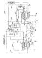
- the inlet to the refrigeration medium heat exchanger coil 90 of evaporator vessel 60 is connected by a pipe 100 to a cooling load and the outlet thereof is connected by another pipe 102 to the inlet of medium cooling means or cooler 110 of a mechanical refrigeration system generally 108 having a centrifugal compressor 112.
- the outlet of the cooler 110 is connectable through a pump 116 and a two position valve 118 to a pipe 120 to the cooling load.
- the in-place mechanical system 108 will include a cooler 110 that already cools a refrigerant medium, typically water, for circulation to the cooling load and that medium will be available to both phases of the absorption system.
- a refrigerant medium typically water
- the inlet to the second heat exchanger coil 92 of the absorber section is connected by a pipe 122 to a heat ejector such as a spray tower; and the outlet of the heat exchanger coil 92 is connected by pipe 124 through a pump 126 and a two position valve 128 to the inlet of a heat extractor 130 of the mechanical system.
- the heat extractor outlet is connected by a pipe 134 to the ejector (spray tower).
- the second heat exchanger coil 92 in the evaporator section of the absorber-evaporator vessel 60 receives cooling fluid through pipe 122 from a heat ejector (spray tower) and passes that fluid via pipe 124, valve 128 and pump 126 through the mechanical system heat extractor 130; and the heated fluid is returned to the heat ejector (spray tower) through pipe 134.
- the refrigerant medium and heat ejector fluid circuits are blocked by repositioning valves 118 and 128 and chilled water from the mechanical system cooler 110 is circulated by pump 116 via valve 118 through pipes 140 and 142 through coil 14 of the condenser section in concentrator vessel 10; and the generator section coil 12 receives a circulation of hot fluid via pipes 148, 150 connecting a dedicated compressor 152.
- the heat output of the dedicated compressor 152 is boosted by warming the fluid circulated through pipe 150 after passing an expansion valve 154 with warm fluid such as water circulated through a heat exchanger 156 from the heat extractor 130, associated with the mechanical system centrifugal compressor 112, through pipes 158 and 160 and valve 128.
- the dedicated compressor the temperature of fluid to the coil 12 in the generator section can be raised to about 135" where as the fluid available at the heat extractor 130 will typically be about 100 F.
- valve 118 when the two position valve 118 is positioned to direct flow through pipe 120 it will block flow in either direction through the closed circuit of pipes 140, 142 and coil 14. Conversely, during a storage cycle, when the valve 118 is positioned to direct flow into pipe 140 it will block in either direction through the closed circuit of the cooling load and pipes 120, 100, 102 and coil 90. Similarly when, during a cooling cycle, the two position valve 128 is positioned to permit flow from pipe 124 it serves to block flow in either direction through the circuit comprising pipes 158 and 160. Conversely, during a storage cycle, when valve 128 is positioned to direct flow through the pipes 158 and 160 it will block flow in either direction through the spray tower.
- FIGURE 5 a similar combined absorption and mechanical system is shown utilizing a reciprocating compressor 172.
- the piping connections between the evaporator vessel 60 and the mechanical refrigeration system generally 108' and operation during a cooling cycle are the same as the embodiment of FIGURE 4 and parts common to the two embodiments bear the same reference characters.
- the reciprocating compressor 172 is normally capable of rejecting heat through the heat extractor 130' at higher temperatures (typically about 140 ° F as compared to about 104" F for a centrifugal compressor)
- the generator section coil 12 of the absorber system concentrator vessel 10 is connected for direct circulation of hot water from the heat extractor 130' through pipes 178, 180 during the storage cycle and, as in the embodiment of FIGURE 4, the condenser section coil 14 is connected by pipes 140', 142' to receive cold water circulated directly from the mechanical system chiller 110'.
- FIGURE 6 a combined absorber and mechanical system preferred for new or original installation is shown to include similar connections between the absorber system evaporator vessel 60 and the mechanical refrigeration system generally 108" and operation during a cooling cycle is substantially the same as in the embodiment of FIGURE 4 and 5, However, in such an initial installation it is possible to provide for alternatively circulating the refrigerant gas from a reciprocating compressor 192 to a direct expansion cooler 194 during a cooling cycle and to the coils 12 and 14 of the absorber concentrator vessel 10 during a storage cycle.
- the absorber system evaporator vessel 60 is connected to the cooler 194 and the heat extractor 130" of the mechanical system generally 108" similar to the embodiments of FIGURES 4 and 5 and functions in the same manner during a cooling cycle.
- valve 200 leads directly to a heat extractor 130" and valve 202 leads to the heat extractor via conduits 212 and 214 and the condenser coil 12.
- Refrigerant liquid lines 204 and 216 lead from the heat extractor 130" and are equipped with solenoid valves 222 and 224, respectively.
- Valves 200 and 222 are opened and valves 202 and 224 are closed during the cooling cycle to circulate the compressed refrigerant fluid (gas) through the heat extractor 130" (where it is cooled and condensed by water directed through pipes 124" and 134" to a spray tower) and the resultant refrigerant liquid is directed thence through pipe 204 and thermostatic expansion valve 206 to the direct expansion cooler 194 where it is again vaporized and returned to the suction side of compressor 192 through a pipe 208.
- the cooler 194 operates to cool refrigerant medium received from the absorber-evaporator vessel 60 through pipe 102" and circulate the medium to the cooling load via pipe 120".
- valves 200 and 222 are closed (thereby making both the cooler 194 and the heat extractor 130" inoperative) and valves 202 and 224 are opened to direct the hot compressed fluid to circulate through conduit 212 and the coil 12 in the generator section of concentrator vessel 10 and thence through conduit 214 and the idle heat extractor 130" into conduit 216 and through a second thermostatic expansion valve 218 to the coil 14 in the condenser section of vessel 10 From the latter, the refrigerant gas is returned to the compressor 192 via a conduit 220.
- the concentrator vessel 10 functions during a storage cycle as in the embodiment of FIGURE 1, to produce quantities of strong absorbent solution and a diluent which are stored in reservoir vessels 40, 50 against demand in the evaporator vessel 60 during a cooling cycle.
- quantities of a weak absorbent solution will be produced in the evaporator vessel 60 and stored in reservoir vessel 70.
- the total combined quantities of strong and weak absorbent solutions will be substantially constant and will run about 0.75-1.0 cubic feet per Ton-Hour of stored cooling capability. For a typical office building operating profile, this would amount to 3.0-5.0 cubic feet for each ton of design building cooling load.
- a combined refrigeration method and apparatus of improved efficiency there is provided an absorption refrigeration method and apparatus combined with a mechanical expansion refrigeration system so as to indirectly utilize electrical energy as a power source for the absorption system; and there is provided an absorption refrigeration method and apparatus which are energized by a mechanical refrigeration system; and there is provided an absorption refrigeration method and apparatus which are energized by a mechanical refrigeration system to produce and store quantities of a strong absorbent solution and a cold liquid diluent during the concentrator phase for subsequent use when the absorber phase is used to supplement the cooling capacity of the mechanical refrigeration system.
Landscapes
- Engineering & Computer Science (AREA)
- Physics & Mathematics (AREA)
- Mechanical Engineering (AREA)
- Thermal Sciences (AREA)
- General Engineering & Computer Science (AREA)
- Chemical & Material Sciences (AREA)
- Materials Engineering (AREA)
- Sorption Type Refrigeration Machines (AREA)
Applications Claiming Priority (2)
| Application Number | Priority Date | Filing Date | Title |
|---|---|---|---|
| US07/604,577 US5038574A (en) | 1989-05-12 | 1990-10-26 | Combined mechanical refrigeration and absorption refrigeration method and apparatus |
| US604577 | 2004-08-25 |
Publications (1)
| Publication Number | Publication Date |
|---|---|
| EP0482738A1 true EP0482738A1 (fr) | 1992-04-29 |
Family
ID=24420187
Family Applications (1)
| Application Number | Title | Priority Date | Filing Date |
|---|---|---|---|
| EP91305609A Withdrawn EP0482738A1 (fr) | 1990-10-26 | 1991-06-20 | Procédé et appareil frigorifique mécanique et à absorption combinée |
Country Status (8)
| Country | Link |
|---|---|
| US (1) | US5038574A (fr) |
| EP (1) | EP0482738A1 (fr) |
| JP (1) | JPH04268172A (fr) |
| AU (1) | AU631343B2 (fr) |
| BR (1) | BR9102930A (fr) |
| CA (1) | CA2044322C (fr) |
| PT (1) | PT97981A (fr) |
| ZA (1) | ZA914525B (fr) |
Cited By (4)
| Publication number | Priority date | Publication date | Assignee | Title |
|---|---|---|---|---|
| RU2152566C1 (ru) * | 1999-06-08 | 2000-07-10 | Донская государственная академия сервиса | Стенд для испытания абсорбционно-компрессионного холодильного агрегата |
| WO2010038037A1 (fr) * | 2008-10-03 | 2010-04-08 | Energyexcel Llp | Procédés et dispositif de refroidissement |
| WO2010089317A3 (fr) * | 2009-02-04 | 2010-12-09 | Universität Kassel | Réservoir |
| CN106524578A (zh) * | 2016-12-16 | 2017-03-22 | 北京联力源科技有限公司 | 吸收式储能系统、供能系统及方法 |
Families Citing this family (32)
| Publication number | Priority date | Publication date | Assignee | Title |
|---|---|---|---|---|
| DE19535840C2 (de) * | 1995-09-15 | 1997-12-18 | Umsicht Inst Umwelt Sicherheit | Absorptionskältemaschine und Verfahren zu deren Betrieb |
| US5367884B1 (en) | 1991-03-12 | 1996-12-31 | Phillips Eng Co | Generator-absorber-heat exchange heat transfer apparatus and method and use thereof in a heat pump |
| US5271235A (en) | 1991-03-12 | 1993-12-21 | Phillips Engineering Company | High efficiency absorption cycle of the gax type |
| US5212961A (en) * | 1991-10-15 | 1993-05-25 | Graf William J | Dual cycle water chiller |
| US5570584A (en) | 1991-11-18 | 1996-11-05 | Phillips Engineering Co. | Generator-Absorber heat exchange transfer apparatus and method using an intermediate liquor |
| US5383339A (en) * | 1992-12-10 | 1995-01-24 | Baltimore Aircoil Company, Inc. | Supplemental cooling system for coupling to refrigerant-cooled apparatus |
| US5386709A (en) * | 1992-12-10 | 1995-02-07 | Baltimore Aircoil Company, Inc. | Subcooling and proportional control of subcooling of liquid refrigerant circuits with thermal storage or low temperature reservoirs |
| US5440894A (en) * | 1993-05-05 | 1995-08-15 | Hussmann Corporation | Strategic modular commercial refrigeration |
| US5579652A (en) | 1993-06-15 | 1996-12-03 | Phillips Engineering Co. | Generator-absorber-heat exchange heat transfer apparatus and method and use thereof in a heat pump |
| US5419145A (en) * | 1994-01-13 | 1995-05-30 | Rocky Research | Chemical energy storage system |
| US5829259A (en) * | 1994-01-13 | 1998-11-03 | Rocky Research | Aqueous absorption fluids |
| US5577388A (en) * | 1994-01-13 | 1996-11-26 | Rocky Research | Aqueous absorption fluids |
| US5490393A (en) * | 1994-03-31 | 1996-02-13 | Robur Corporation | Generator absorber heat exchanger for an ammonia/water absorption refrigeration system |
| US5782097A (en) | 1994-11-23 | 1998-07-21 | Phillips Engineering Co. | Generator-absorber-heat exchange heat transfer apparatus and method and use thereof in a heat pump |
| US5727393A (en) * | 1996-04-12 | 1998-03-17 | Hussmann Corporation | Multi-stage cooling system for commerical refrigeration |
| US5743102A (en) * | 1996-04-15 | 1998-04-28 | Hussmann Corporation | Strategic modular secondary refrigeration |
| TW325516B (en) * | 1996-04-25 | 1998-01-21 | Chugoku Electric Power | Compression/absorption combined type heat pump |
| US5921092A (en) * | 1998-03-16 | 1999-07-13 | Hussmann Corporation | Fluid defrost system and method for secondary refrigeration systems |
| US6187220B1 (en) | 1999-03-26 | 2001-02-13 | Gas Research Institute | Ether heat and mass transfer additives for aqueous absorption fluids |
| US8631657B2 (en) * | 2003-01-22 | 2014-01-21 | Vast Power Portfolio, Llc | Thermodynamic cycles with thermal diluent |
| WO2007015696A1 (fr) * | 2005-08-01 | 2007-02-08 | Mohammed Alam | Systeme d’echange de chaleur a actionnement et regulation automatiques |
| JP2009098823A (ja) * | 2007-10-16 | 2009-05-07 | Hitachi Ltd | 電子装置システム |
| US8146374B1 (en) * | 2009-02-13 | 2012-04-03 | Source IT Energy, LLC | System and method for efficient utilization of energy generated by a utility plant |
| US8984897B2 (en) * | 2009-09-16 | 2015-03-24 | International Business Machines Corporation | Endothermic reaction apparatus for removing excess heat in a datacenter |
| US8474277B2 (en) * | 2010-07-13 | 2013-07-02 | General Electric Company | Compressor waste heat driven cooling system |
| JP5850051B2 (ja) * | 2011-07-04 | 2016-02-03 | 富士通株式会社 | 吸着式ヒートポンプの制御方法、情報処理システム及び制御装置 |
| WO2013134553A1 (fr) * | 2012-03-09 | 2013-09-12 | Bluelagoon Technologies Ltd | Appareil et procédé pour des pompes à chaleur à absorption entraînées par la vapeur et transformateur de chaleur à absorption ayant des applications |
| WO2014168785A1 (fr) * | 2013-04-11 | 2014-10-16 | Carrier Corporation | Principe de cycle combiné d'absorption de vapeur et de compression mécanique |
| US9459027B2 (en) | 2014-04-22 | 2016-10-04 | King Fahd University Of Petroleum And Minerals | Intermittent absorption refrigeration system |
| DE112015007034T5 (de) | 2015-11-26 | 2018-07-19 | Dometic Sweden Ab | Hybridkühlgerät |
| EP3390928A1 (fr) * | 2015-12-18 | 2018-10-24 | Bry-Air (Asia) Pvt. Ltd. | Dispositifs à cycle hybride de compression-adsorption de vapeur et leur procédé de mise en oeuvre |
| CN119146623A (zh) * | 2016-10-05 | 2024-12-17 | 江森自控泰科知识产权控股有限责任合伙公司 | 用于hvac&r系统的热泵 |
Citations (4)
| Publication number | Priority date | Publication date | Assignee | Title |
|---|---|---|---|---|
| FR2374603A1 (fr) * | 1976-12-20 | 1978-07-13 | Carrier Corp | Appareil de refrigeration a absorption utilisant l'energie solaire |
| US4269041A (en) * | 1979-01-04 | 1981-05-26 | Borsig Gmbh | Absorption refrigerating machine with storage device for operation with yield of heat energy and refrigerating requirement different in time |
| US4471630A (en) * | 1982-01-29 | 1984-09-18 | Hitachi, Ltd. | Cooling system having combination of compression and absorption type units |
| EP0143736A2 (fr) * | 1983-09-01 | 1985-06-05 | ATP Arbeitsgruppe Technische Photosynthese GmbH & Co. Produktions KG | Pompe à chaleur chimique à alimentation en énergie mécanique ou électrique |
Family Cites Families (18)
| Publication number | Priority date | Publication date | Assignee | Title |
|---|---|---|---|---|
| US3138938A (en) * | 1962-12-20 | 1964-06-30 | Montcalm Inc | Absorption refrigeration apparatus |
| US3360950A (en) * | 1965-11-30 | 1968-01-02 | Carrier Corp | Purge arrangement for absorption refrigeration systems |
| US3320760A (en) * | 1966-04-19 | 1967-05-23 | Judson S Swearingen | Rapidly variable capacity absorption refrigeration system |
| US3563304A (en) * | 1969-01-28 | 1971-02-16 | Carrier Corp | Reverse cycle refrigeration system utilizing latent heat storage |
| US3745780A (en) * | 1970-03-18 | 1973-07-17 | Carrier Corp | Absorption refrigeration system |
| US3651655A (en) * | 1970-08-10 | 1972-03-28 | Carrier Corp | Control system for multiple stage absorption refrigeration system |
| US3742727A (en) * | 1971-06-02 | 1973-07-03 | Carrier Corp | Absorption refrigeration system |
| US3742726A (en) * | 1971-06-02 | 1973-07-03 | Carrier Corp | Absorption refrigeration system |
| US3701265A (en) * | 1971-06-21 | 1972-10-31 | Carrier Corp | Absorption refrigeration system |
| US3824804A (en) * | 1973-08-22 | 1974-07-23 | C Sandmark | Refrigerating machines |
| JPS52106146A (en) * | 1976-03-03 | 1977-09-06 | Hitachi Ltd | Solution heat exchanger for absorption refrigerating machine |
| US4246762A (en) * | 1978-06-08 | 1981-01-27 | Carrier Corporation | Absorption refrigeration system |
| JPS5514416A (en) * | 1978-07-14 | 1980-01-31 | Toyota Motor Co Ltd | Absorption type regenerative refrigerator |
| US4513584A (en) * | 1980-01-10 | 1985-04-30 | Woyke John F | Method and apparatus for absorption refrigeration |
| US4337625A (en) * | 1981-03-02 | 1982-07-06 | Battelle Development Corp. | Waste heat driven absorption refrigeration process and system |
| JPS588961A (ja) * | 1981-07-10 | 1983-01-19 | 株式会社日立製作所 | 吸収式ヒ−トポンプ |
| US4724679A (en) * | 1986-07-02 | 1988-02-16 | Reinhard Radermacher | Advanced vapor compression heat pump cycle utilizing non-azeotropic working fluid mixtures |
| ES2036677T3 (es) * | 1987-04-14 | 1993-06-01 | Uwe Rockenfeller | Sistema de acumulacion de energia quimica. |
-
1990
- 1990-10-26 US US07/604,577 patent/US5038574A/en not_active Expired - Fee Related
-
1991
- 1991-06-11 CA CA002044322A patent/CA2044322C/fr not_active Expired - Fee Related
- 1991-06-13 ZA ZA914525A patent/ZA914525B/xx unknown
- 1991-06-14 PT PT97981A patent/PT97981A/pt not_active Application Discontinuation
- 1991-06-17 AU AU78466/91A patent/AU631343B2/en not_active Ceased
- 1991-06-20 EP EP91305609A patent/EP0482738A1/fr not_active Withdrawn
- 1991-07-10 BR BR919102930A patent/BR9102930A/pt not_active IP Right Cessation
- 1991-10-25 JP JP3280100A patent/JPH04268172A/ja active Pending
Patent Citations (4)
| Publication number | Priority date | Publication date | Assignee | Title |
|---|---|---|---|---|
| FR2374603A1 (fr) * | 1976-12-20 | 1978-07-13 | Carrier Corp | Appareil de refrigeration a absorption utilisant l'energie solaire |
| US4269041A (en) * | 1979-01-04 | 1981-05-26 | Borsig Gmbh | Absorption refrigerating machine with storage device for operation with yield of heat energy and refrigerating requirement different in time |
| US4471630A (en) * | 1982-01-29 | 1984-09-18 | Hitachi, Ltd. | Cooling system having combination of compression and absorption type units |
| EP0143736A2 (fr) * | 1983-09-01 | 1985-06-05 | ATP Arbeitsgruppe Technische Photosynthese GmbH & Co. Produktions KG | Pompe à chaleur chimique à alimentation en énergie mécanique ou électrique |
Cited By (4)
| Publication number | Priority date | Publication date | Assignee | Title |
|---|---|---|---|---|
| RU2152566C1 (ru) * | 1999-06-08 | 2000-07-10 | Донская государственная академия сервиса | Стенд для испытания абсорбционно-компрессионного холодильного агрегата |
| WO2010038037A1 (fr) * | 2008-10-03 | 2010-04-08 | Energyexcel Llp | Procédés et dispositif de refroidissement |
| WO2010089317A3 (fr) * | 2009-02-04 | 2010-12-09 | Universität Kassel | Réservoir |
| CN106524578A (zh) * | 2016-12-16 | 2017-03-22 | 北京联力源科技有限公司 | 吸收式储能系统、供能系统及方法 |
Also Published As
| Publication number | Publication date |
|---|---|
| AU7846691A (en) | 1992-04-30 |
| JPH04268172A (ja) | 1992-09-24 |
| CA2044322A1 (fr) | 1992-04-27 |
| PT97981A (pt) | 1993-06-30 |
| US5038574A (en) | 1991-08-13 |
| CA2044322C (fr) | 1994-02-22 |
| BR9102930A (pt) | 1992-06-16 |
| AU631343B2 (en) | 1992-11-19 |
| ZA914525B (en) | 1992-03-25 |
Similar Documents
| Publication | Publication Date | Title |
|---|---|---|
| US5038574A (en) | Combined mechanical refrigeration and absorption refrigeration method and apparatus | |
| US4966007A (en) | Absorption refrigeration method and apparatus | |
| US5816070A (en) | Enhanced lithium bromide absorption cycle water vapor recompression absorber | |
| CA1088729A (fr) | Methode et appareil de transfert d'energie dans un systeme a absorption | |
| US3675441A (en) | Two stage refrigeration plant having a plurality of first stage refrigeration systems | |
| US4171619A (en) | Compressor assisted absorption refrigeration system | |
| US2411347A (en) | Refrigerant vapor system | |
| US5024063A (en) | Branched gax absorption vapor compressor | |
| WO1991008426A1 (fr) | Reflux de rectification par echange de chaleur latente avec un absorbant partiellement depressurise | |
| CA2112902C (fr) | Systeme de refrigeration par absorption a triple effet comprenant un raccord de condenseur double | |
| US4448030A (en) | Combined staged air conditioner and heat store | |
| EP0897516B1 (fr) | Appareil et procede d'echange et de transfert de chaleur du type generateur-absorbeur et procede d'utilisation de ce dernier dans une pompe a chaleur | |
| EP0309552A4 (en) | Integrated cascade refrigeration system | |
| US5966948A (en) | Sub-ambient absorber GAX cycle | |
| Kühnl-Kinel | New age water chillers with water as refrigerant | |
| US4240267A (en) | System for vaporizing carbon dioxide utilizing the heat by-product of the refrigeration system as a heat source | |
| US11604018B1 (en) | Low pressure refrigeration system | |
| GB2305235A (en) | An ejector device for use in a heat pump | |
| CN216522468U (zh) | 一种压缩式氨气制冷系统 | |
| JPH08285401A (ja) | 蒸気圧縮機を用いた冷温水供給装置 | |
| SU1330419A1 (ru) | Абсорбционна гелиохолодильна установка | |
| WO2025252527A1 (fr) | Système de réfrigération conçu pour fonctionner dans de multiples modes en fonction des conditions ambiantes | |
| KR920007450Y1 (ko) | 자동차의 엔진 폐열을 이용한 흡수식 냉방장치 | |
| JPS6257840B2 (fr) | ||
| JPH0359352A (ja) | ヒートポンプ装置 |
Legal Events
| Date | Code | Title | Description |
|---|---|---|---|
| PUAI | Public reference made under article 153(3) epc to a published international application that has entered the european phase |
Free format text: ORIGINAL CODE: 0009012 |
|
| AK | Designated contracting states |
Kind code of ref document: A1 Designated state(s): AT BE CH DE ES FR GB IT LI NL |
|
| 17P | Request for examination filed |
Effective date: 19920508 |
|
| 17Q | First examination report despatched |
Effective date: 19921214 |
|
| STAA | Information on the status of an ep patent application or granted ep patent |
Free format text: STATUS: THE APPLICATION IS DEEMED TO BE WITHDRAWN |
|
| 18D | Application deemed to be withdrawn |
Effective date: 19930427 |