EP0482760A1 - Procédé et appareil pour suppression de champ magnétique utilisant des boucles passives inductives résonantes et non-résonantes pour tube à rayon cathodique - Google Patents
Procédé et appareil pour suppression de champ magnétique utilisant des boucles passives inductives résonantes et non-résonantes pour tube à rayon cathodique Download PDFInfo
- Publication number
- EP0482760A1 EP0482760A1 EP91308652A EP91308652A EP0482760A1 EP 0482760 A1 EP0482760 A1 EP 0482760A1 EP 91308652 A EP91308652 A EP 91308652A EP 91308652 A EP91308652 A EP 91308652A EP 0482760 A1 EP0482760 A1 EP 0482760A1
- Authority
- EP
- European Patent Office
- Prior art keywords
- crt
- magnetic field
- loop
- yoke
- circuit
- Prior art date
- Legal status (The legal status is an assumption and is not a legal conclusion. Google has not performed a legal analysis and makes no representation as to the accuracy of the status listed.)
- Granted
Links
- 230000005291 magnetic effect Effects 0.000 title claims abstract description 108
- 238000000034 method Methods 0.000 title claims abstract description 17
- 230000001939 inductive effect Effects 0.000 title claims abstract description 16
- 230000001629 suppression Effects 0.000 title description 4
- 239000003990 capacitor Substances 0.000 claims abstract description 9
- 239000004020 conductor Substances 0.000 claims 2
- 230000005855 radiation Effects 0.000 abstract description 6
- 230000000007 visual effect Effects 0.000 abstract description 6
- 230000004907 flux Effects 0.000 abstract description 2
- 239000011521 glass Substances 0.000 description 8
- 238000010894 electron beam technology Methods 0.000 description 6
- 230000005684 electric field Effects 0.000 description 3
- 238000004804 winding Methods 0.000 description 3
- 238000009125 cardiac resynchronization therapy Methods 0.000 description 2
- 238000002788 crimping Methods 0.000 description 2
- 238000005476 soldering Methods 0.000 description 2
- 230000003321 amplification Effects 0.000 description 1
- 238000005452 bending Methods 0.000 description 1
- 230000008901 benefit Effects 0.000 description 1
- 230000008859 change Effects 0.000 description 1
- 238000010276 construction Methods 0.000 description 1
- 230000003292 diminished effect Effects 0.000 description 1
- 230000005294 ferromagnetic effect Effects 0.000 description 1
- 239000000463 material Substances 0.000 description 1
- 238000012986 modification Methods 0.000 description 1
- 230000004048 modification Effects 0.000 description 1
- 238000003199 nucleic acid amplification method Methods 0.000 description 1
- 230000007704 transition Effects 0.000 description 1
Images

Classifications
-
- H—ELECTRICITY
- H01—ELECTRIC ELEMENTS
- H01J—ELECTRIC DISCHARGE TUBES OR DISCHARGE LAMPS
- H01J29/00—Details of cathode-ray tubes or of electron-beam tubes of the types covered by group H01J31/00
- H01J29/46—Arrangements of electrodes and associated parts for generating or controlling the ray or beam, e.g. electron-optical arrangement
- H01J29/70—Arrangements for deflecting ray or beam
- H01J29/72—Arrangements for deflecting ray or beam along one straight line or along two perpendicular straight lines
- H01J29/76—Deflecting by magnetic fields only
-
- H—ELECTRICITY
- H01—ELECTRIC ELEMENTS
- H01J—ELECTRIC DISCHARGE TUBES OR DISCHARGE LAMPS
- H01J29/00—Details of cathode-ray tubes or of electron-beam tubes of the types covered by group H01J31/00
- H01J29/003—Arrangements for eliminating unwanted electromagnetic effects, e.g. demagnetisation arrangements, shielding coils
-
- H—ELECTRICITY
- H01—ELECTRIC ELEMENTS
- H01J—ELECTRIC DISCHARGE TUBES OR DISCHARGE LAMPS
- H01J2229/00—Details of cathode ray tubes or electron beam tubes
- H01J2229/0007—Elimination of unwanted or stray electromagnetic effects
- H01J2229/0015—Preventing or cancelling fields leaving the enclosure
- H01J2229/0023—Passive means
Definitions
- the present invention relates to an apparatus and methods for reducing the stray magnetic fields created by a cathode ray tube (CRT) visual display, and, in particular, to apparatus and methods for passively inducing an opposing magnetic field to reduce the stray magnetic field emitted from a CRT enclosure.
- CTR cathode ray tube
- CRTs are commonly used in televisions and in connection with computers as visual display devices.
- the CRT operates by producing a beam of electrons, which is then scanned across a fluorescent screen.
- the scanning of the electron beam is accomplished by a deflection circuit controlling an electro-magnet known as the yoke.
- the yoke surrounds the CRT just before the CRT flares out to form the enlarged portion of the CRT containing the fluorescent screen.
- the electron beam may be deflected in any desired direction, and thus scanned over the CRT screen to produce an image.
- the yoke creates a wide ranging stray magnetic field. This stray field, although not affecting the CRT whose yoke created the field, can deliteriously affect other CRTs or instruments sensitive to magnetic fields.
- bucking coils in series with the yoke.
- These coils also known as compensating coils, are physically formed so as to produce a magnetic field to oppose the magnetic field produced by the yoke.
- the total magnetic field outside of the CRT enclosure in fact is diminished, several disadvantages become apparent.
- the current necessary to create a functional compensating magnetic field reduces the efficiency of the entire deflection circuit.
- the bucking coil current typically is of the order of fifteen amperes, requiring a large power supply.
- the deflection voltage on the yoke itself must be increased, which affects CRT picture quality.
- the bucking coils are in series with the yoke, any change in the bucking circuit can directly affect the CRT picture quality.
- magnetic suppression by the bucking coils may inadequately prevent magnetic radiation emission from CRT enclosures, particularly in radiation sensitive applications.
- one objective of the present invention is provide an uncomplicated apparatus for, and method of, reducing the stray magnetic fields emitted from CRT enclosures.
- Another objective of the present invention is to provide a less costly apparatus for, and method of, reducing CRT stray magnetic fields. Using the teachings of the present invention, a compensation circuit is available at significant savings compared to prior art embodiments.
- Yet another objective is to disclose a more effective apparatus for, and method of, reducing CRT stray magnetic fields.
- CRT stray magnetic fields are suppressed more effectively than using the teachings of the prior art.
- suppression profiles can be optimized for particular environments.
- the present invention provides an apparatus and methods to reduce the stray magnetic fields emitted from a cathode ray tube (CRT) visual display device created by the CRT yoke assembly
- CRT cathode ray tube
- a pair of closed wire loops are brought into contact with the yoke at the point where maximum magnetic radiation is emitted.
- the first loop in dose proximity to the CRT, circumferentially extends to the sides of the CRT enclosure.and to the top edge of the CRT display face.
- the second loop also in close proximity to the CRT, circumferentially extends to the sides and rear of the CRT enclosure.
- the magnetic flux emitted from the yoke is coupled into the wire loop pair, inducing therein a current which flows so as to produce an opposing magnetic field to that produced by the CRT yoke.
- a capacitor in series in the second loop serves to create a resonant circuit to increase the current flow in the second loop. Measured at a distance, the counteracting magnetic field reduces the total magnetic field emitted from the CRT enclosure.
- CTR cathode ray tube
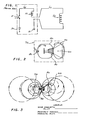
- FIGURE 1 an electrical circuit representing the prior art is disclosed, wherein a compensating magnetic field is actively created to oppose the magnetic field created by a CRT deflection yoke assembly 10.
- Yoke 10 consists of a ferromagnetic ring or annulus, around which is wound a number of loops of conducting wire, and which is physically positioned on the CRT, in a configuration well known in the art (not shown).
- a power supply 30 which drives the scanning function is connected to the yoke assembly 10 via an electronic switch 5.
- the remainder of the deflection circuitry 14 is completed to ground 15.
- bucking coils 20 are physically located above and below yoke 10.
- the deflection power supply 30 connected to yoke 10 is also series connected to bucking coils 20.
- current iy through yoke 10 equals current i c through bucking coils 20.
- Bucking coils 20 are physically formed so that when current i c flows through bucking coils 20, a magnetic field is created opposite in sense to that created by yoke 10.
- current, i c typically amounts to 15 amperes peak-to peak, at a typical deflection voltage of 1000 volts peak-to-peak.
- the subject invention eliminates the high-power inefficient active circuit illustrated in Figure 1 to reduce the stray magnetic fields emitted from the CRT enclosure, by using a simple pair of inductively coupled passive wire loops to create a magnetic field opposite to the yoke-induced field.
- FIGURE 2 illustrates in top plan view a CRT visual display employing the teachings of the present invention.
- a deflection yoke 30 surrounds a CRT 60 as is known in the prior art.
- a front loop 40 and a back loop 50 are placed above a CRT 60 and in close proximity therewith.
- the entire apparatus is housed within an enclosure 70. Attention is now directed for the moment to front loop 40.
- Front loop 40 is formed into a generally circular shape, and is then brought into tangential contact with the front of yoke 30. The precise point of contact is where the front face of yoke 30 contacts the glass envelope of CRT 60.
- front loop 40 then circumferentially extends laterally to the sides of enclosure 70, and forward to the top edge of the CRT 60 where the image screen of CRT 60 contacts enclosure 70.
- front loop 40 also follows the profile of CRT 60, as CRT 60 transitions from the smaller diameter of the electron beam source to the larger diameter of the CRT screen.
- yoke 30 acts as a transformer: the changing magnetic field created by yoke 30 induces an electric field, which passively causes an induced current i 1 to flow in front loop 40.
- a maximum inducted current i 1 in front loop 40 is ensured by the tangential placement of front loop 40 at the yoke-to-glass interface, where stray magnetic radiation is at a maximum.
- the induced current i 1 flows to oppose the magnetic field creating it.
- the flow of electrons in front loop 40 comprising induced current i 1 itself creates a loop-induced magnetic field.
- the loop-induced magnetic field created by the opposing induced current i 1 therefore is opposite in sense to the magnetic field created by yoke 30.
- the passive loop-induced opposing magnetic field subtracts from the actively created yoke-field at distant points, resulting in a reduced total magnetic field emitted from CRT enclosure 70.
- Back loop 50 is formed into a generally rectangular shape, and is brought into tangential contact with yoke 30 at precisely the same point as front loop 40, namely where the front face of yoke 30 contacts the glass envelope of CRT 60. From its tangential contact point, back loop 50 then generally follows the perimeter of CRT enclosure 70, extending laterally to both sides and then rearward to the rear of enclosure 70.
- yoke 30 acts as a transformer: the changing magnetic field created by yoke 30 inducts an electric field, which passively causes an induced current i 2 to flow in back loop 50.
- a maximum induced current i 2 in back loop 50 is ensured by the tangential placement of back loop 50 at the yoke-to-glass interface, where stray magnetic radiation is at a maximum.
- the induced current i 2 flows to oppose the magnetic field creating it.
- the flow of electrons comprising induced current i 2 in turn creates a back loop-induced magnetic field.
- the loop-induced magnetic field created by the opposing induced current i 2 is therefore opposite in sense to the magnetic field created by yoke 30.
- the passive loop-induced opposing magnetic field subtracts from the actively created yoke-field at distant points, again resulting in a reduced total magnetic field emitted from CRT enclosure 70.
- front loop 40 and back loop 50 passively create magnetic fields which, in concert, reduce the total magnetic field emitted from CRT enclosure 70.
- a capacitor 80 is added in series to increase the magnitude of induced current i 2 , the amplification being achieved by forming a near- resonant "LC" type circuit at the particular deflection frequency of CRT 60.
- a capacitor 80 capacitance of 3.5 microfarad increases the induced back loop current i 2 flowing in back loop 50 from 3 amperes to approximately 15 amperes, thereby more effectively reducing the stray field to the rear of CRT 60.
- neither front loop 40 nor back loop 50 in FIGURE 2 are electrically coupled to the deflection circuitry. Rather, both are magnetically coupled to the deflection circuit at the yoke 30, with yoke 30 acting as a transformer.
- Front loop 40 and back loop 50 function simply acoording to Faraday's and Lenz's Laws: (i) currents i 1 and i 2 are passively induced by the the electric field produced by the changing stray magnetic field, and (ii) induced currents i 1 and i 2 flow to oppose the changing stray field, thereby creating opposing magnetic fields which subtract from the yoke-created stray field.
- the advantage of the present invention is that a reduced total magnetic field is emitted from the CRT enclosure 70 without the use of active circuits. Moreover, it is seen that the reduced total magnetic field is accomplished without dependence upon the deflection circuit's, or any circuit's, power supply.
- FIGURE 3 a side elevation view is shown of the present invention in place above CRT 60.
- the front loop 40 and back loop 50 are seen to traverse the length of CRT 60, tangentially contacting the front of a yoke 30 at the yoke-to-glass interface.
- FIGURE 3 shows clearly the positioning of front loop 40 and back loop 50 in close proximity to CRT 60.
- attention is directed to the position of front loop 40 relative to CRT 60, as the profile of CRT 60 changes from the narrow diameter of the electron gun portion to the larger diameter of the display screen portion.
- front loop 40 remains generally equidistant from CRT 60 throughout. The bend in front loop 40 permits it to pass over CRT 60 while projecting forward the passively induced opposing magnetic field.
- FIGURE 3 Attention is now directed to the opposing magnetic fields which are formed during the operation of a CRT display device employing the teachings of the present invention.
- the magnetic field actively created by yoke 30 is shown by a solid line.
- the opposing magnetic field passively induced by front loop 40 and back loop 50 is shown by a dashed line.
- FIGURE 4 empirical total emitted magnetic field strength is plotted against distance for 17-and 19-inch CRT monitors equipped with the present invention.
- test monitors using the present invention are shown to satisfy the German VDE Agency specification of 34 dB/j 1 .V at 20 meters.
- a monitor using a standard prior art bucking coil circuit is not in compliance until 30 meters. Note that the passive loop suppression is independent of monitor size.
- the cancellation of the yoke-induced field is more effective using the teachings of the present invention than prior art teachings.
- FIGURES 5a and 5b illustrate the preferred embodiment of front loop 40 and back loop 50 comprising the present invention applied to a 17- inch CRT monitor.
- front loop 40 is shown to be constructed of two wire arcs of dissimilar diameter.
- the larger circumference arc 45 is fashioned of a 32- inch length of 18 gauge wire, and projects laterally and forward from the yoke to the front of the CRT.
- the smaller circumference arc 46 fashioned of a 10-inch length of 22 gauge wire, is placed into the gap between the yoke (not shown) and the glass comprising CRT (not shown).
- Arcs 45 and 46 are fixedly coupled by any well-known joining method, such as crimping and soldering.
- back loop 50 is fashioned similarly, but the addition of capacitor 80 inserted into the loop necessarily requires three arcs.
- the larger circumference arc 55 and arc 56 are fashioned of two 16- inch lengths of 18 gauge wire, and together project from the yoke (not shown) laterally to the sides and to the rear of the CRT enclosure (not shown).
- the smaller circumference arc 57 as above, is fashioned of a 10-inch length of 22 gauge wire, and is placed into the gap between the yoke (not shown) and the glass comprising CRT (not shown), precisely where front loop 40 contacts the yoke (not shown).
- Back loop large circumference arcs 55 and 56, back loop small circumference arc 57, and capacitor 80 are fixedly coupled by the above pinning method of crimping and soldering.
Landscapes
- Physics & Mathematics (AREA)
- Electromagnetism (AREA)
- Video Image Reproduction Devices For Color Tv Systems (AREA)
- Electrodes For Cathode-Ray Tubes (AREA)
Applications Claiming Priority (2)
| Application Number | Priority Date | Filing Date | Title |
|---|---|---|---|
| US07/602,348 US5107179A (en) | 1990-10-22 | 1990-10-22 | Method and apparatus for magnetic field suppression using inductive resonant and non-resonant passive loops |
| US602348 | 1990-10-22 |
Publications (2)
| Publication Number | Publication Date |
|---|---|
| EP0482760A1 true EP0482760A1 (fr) | 1992-04-29 |
| EP0482760B1 EP0482760B1 (fr) | 1995-01-04 |
Family
ID=24410994
Family Applications (1)
| Application Number | Title | Priority Date | Filing Date |
|---|---|---|---|
| EP91308652A Expired - Lifetime EP0482760B1 (fr) | 1990-10-22 | 1991-09-24 | Procédé et appareil pour suppression de champ magnétique utilisant des boucles passives inductives résonantes et non-résonantes pour tube à rayon cathodique |
Country Status (5)
| Country | Link |
|---|---|
| US (1) | US5107179A (fr) |
| EP (1) | EP0482760B1 (fr) |
| JP (1) | JP3278747B2 (fr) |
| KR (1) | KR950013609B1 (fr) |
| DE (1) | DE69106480T2 (fr) |
Families Citing this family (8)
| Publication number | Priority date | Publication date | Assignee | Title |
|---|---|---|---|---|
| US5350973A (en) * | 1989-08-31 | 1994-09-27 | Kabushiki Kaisha Toshiba | Cathode-ray tube apparatus having a reduced leak of magnetic fluxes |
| DE69207227T2 (de) * | 1991-02-20 | 1996-09-05 | Nanao Corp | Gerät zur Unterdrückung der Strahlung einer Anzeigevorrichtung |
| JPH05290759A (ja) * | 1992-04-09 | 1993-11-05 | Toshiba Corp | 陰極線管装置 |
| US5568112A (en) * | 1992-05-14 | 1996-10-22 | Cure; Jorge | Method and apparatus for reducing the strength of pulsating magnetic fields |
| US5561333A (en) * | 1993-05-10 | 1996-10-01 | Mti, Inc. | Method and apparatus for reducing the intensity of magnetic field emissions from video display units |
| US5594615A (en) * | 1993-05-10 | 1997-01-14 | Mti, Inc. | Method and apparatus for reducing the intensity of magenetic field emissions from display device |
| KR19990006119A (ko) * | 1997-06-30 | 1999-01-25 | 김영환 | 음극선관 전면에서 방사되는 전자기장 상쇄장치 |
| KR100371379B1 (ko) * | 1997-10-09 | 2003-03-26 | 주식회사 엘지이아이 | 영상표시기기의씨알티전면vlf방사전계차폐장치 |
Citations (2)
| Publication number | Priority date | Publication date | Assignee | Title |
|---|---|---|---|---|
| DE2545848A1 (de) * | 1975-10-14 | 1977-04-21 | Licentia Gmbh | Kathodenstrahlroehre mit einer ablenkspulenanordnung |
| EP0322845A2 (fr) * | 1987-12-26 | 1989-07-05 | Kabushiki Kaisha Toshiba | Déflecteur pour tube image couleur |
Family Cites Families (3)
| Publication number | Priority date | Publication date | Assignee | Title |
|---|---|---|---|---|
| JPS60218693A (ja) * | 1984-04-13 | 1985-11-01 | 三菱電機株式会社 | デイスプレイ装置 |
| NL8602397A (nl) * | 1985-10-25 | 1987-05-18 | Philips Nv | Beeldweergeefinrichting met ontstoringsmiddelen. |
| FR2606574B1 (fr) * | 1986-11-07 | 1989-01-13 | Videocolor | Dispositif de protection de tubes cathodiques a masque vis-a-vis du champ magnetique terrestre |
-
1990
- 1990-10-22 US US07/602,348 patent/US5107179A/en not_active Expired - Lifetime
-
1991
- 1991-09-24 DE DE69106480T patent/DE69106480T2/de not_active Expired - Fee Related
- 1991-09-24 EP EP91308652A patent/EP0482760B1/fr not_active Expired - Lifetime
- 1991-10-22 JP JP30132991A patent/JP3278747B2/ja not_active Expired - Fee Related
- 1991-10-22 KR KR1019910018609A patent/KR950013609B1/ko not_active Expired - Fee Related
Patent Citations (2)
| Publication number | Priority date | Publication date | Assignee | Title |
|---|---|---|---|---|
| DE2545848A1 (de) * | 1975-10-14 | 1977-04-21 | Licentia Gmbh | Kathodenstrahlroehre mit einer ablenkspulenanordnung |
| EP0322845A2 (fr) * | 1987-12-26 | 1989-07-05 | Kabushiki Kaisha Toshiba | Déflecteur pour tube image couleur |
Non-Patent Citations (1)
| Title |
|---|
| RESEARCH DISCLOSURE. no. 304, August 1989, HAVANT GB page 598; ANON.: 'Passive VLF Magnetic Remedies' * |
Also Published As
| Publication number | Publication date |
|---|---|
| US5107179A (en) | 1992-04-21 |
| JPH06103924A (ja) | 1994-04-15 |
| DE69106480D1 (de) | 1995-02-16 |
| DE69106480T2 (de) | 1995-07-06 |
| KR920008819A (ko) | 1992-05-28 |
| EP0482760B1 (fr) | 1995-01-04 |
| JP3278747B2 (ja) | 2002-04-30 |
| KR950013609B1 (ko) | 1995-11-13 |
Similar Documents
| Publication | Publication Date | Title |
|---|---|---|
| JP2965073B2 (ja) | 画像表示装置 | |
| EP0482760B1 (fr) | Procédé et appareil pour suppression de champ magnétique utilisant des boucles passives inductives résonantes et non-résonantes pour tube à rayon cathodique | |
| CN1040934C (zh) | 阴极射线管图像显示装置 | |
| EP0346972B1 (fr) | Dispositif de reproduction d'image comportant des moyens de noyau munis de bobines de compensation | |
| US4992697A (en) | Picture display device with magnetizable core means comprising compensation coils | |
| US5350980A (en) | Nonlinear inductor with magnetic field reduction | |
| JP3450867B2 (ja) | ビデオ表示装置 | |
| KR950008407B1 (ko) | 음극선관 디스플레이 장치 | |
| US6630791B2 (en) | Cathode ray tube device that reduces magnetic field leakage | |
| US5841234A (en) | Device for shielding electric field emitted backward from video display appliance | |
| KR100302429B1 (ko) | 디스플레이장치 | |
| JP3448607B2 (ja) | 陰極線管用磁気集束装置 | |
| US5432492A (en) | Deflection yoke apparatus with auxiliar coils to compensensate magnetic leakage | |
| US5736914A (en) | Demagnetizing device for a cathode ray tube | |
| EP0561455A1 (fr) | Transformateur de sortie de ligne | |
| US6144416A (en) | Apparatus of shielding VLF electric field emitted from front face of CRT in video appliance | |
| JPH06103934A (ja) | 表示装置 | |
| JPH05207404A (ja) | 陰極線管装置および陰極線管画像表示装置 | |
| JP3146061B2 (ja) | 陰極線管および陰極線管画像表示装置 | |
| EP0540096B1 (fr) | Appareil à collier de déviation muni de moyens pour réduire les champs magnetiques de fuites | |
| RU2160510C2 (ru) | Видеодисплей со схемой подавления нежелательного излучения электронно-лучевой трубки | |
| JP2000261819A (ja) | 陰極線管の地磁気補正装置及び地磁気補正された陰極線管 | |
| KR20040031033A (ko) | 링잉방지 코일을 구비한 음극선관 | |
| KR960032565A (ko) | 음극선관장치 | |
| JPH0451431A (ja) | 偏向ヨーク |
Legal Events
| Date | Code | Title | Description |
|---|---|---|---|
| PUAI | Public reference made under article 153(3) epc to a published international application that has entered the european phase |
Free format text: ORIGINAL CODE: 0009012 |
|
| AK | Designated contracting states |
Kind code of ref document: A1 Designated state(s): DE FR GB IT |
|
| 17P | Request for examination filed |
Effective date: 19921020 |
|
| 17Q | First examination report despatched |
Effective date: 19940218 |
|
| GRAA | (expected) grant |
Free format text: ORIGINAL CODE: 0009210 |
|
| AK | Designated contracting states |
Kind code of ref document: B1 Designated state(s): DE FR GB IT |
|
| ITF | It: translation for a ep patent filed | ||
| REF | Corresponds to: |
Ref document number: 69106480 Country of ref document: DE Date of ref document: 19950216 |
|
| ET | Fr: translation filed | ||
| PLBE | No opposition filed within time limit |
Free format text: ORIGINAL CODE: 0009261 |
|
| STAA | Information on the status of an ep patent application or granted ep patent |
Free format text: STATUS: NO OPPOSITION FILED WITHIN TIME LIMIT |
|
| 26N | No opposition filed | ||
| REG | Reference to a national code |
Ref country code: GB Ref legal event code: IF02 |
|
| PGFP | Annual fee paid to national office [announced via postgrant information from national office to epo] |
Ref country code: GB Payment date: 20021002 Year of fee payment: 12 Ref country code: DE Payment date: 20021002 Year of fee payment: 12 |
|
| PGFP | Annual fee paid to national office [announced via postgrant information from national office to epo] |
Ref country code: FR Payment date: 20021008 Year of fee payment: 12 |
|
| PG25 | Lapsed in a contracting state [announced via postgrant information from national office to epo] |
Ref country code: GB Free format text: LAPSE BECAUSE OF NON-PAYMENT OF DUE FEES Effective date: 20030924 |
|
| PG25 | Lapsed in a contracting state [announced via postgrant information from national office to epo] |
Ref country code: DE Free format text: LAPSE BECAUSE OF NON-PAYMENT OF DUE FEES Effective date: 20040401 |
|
| GBPC | Gb: european patent ceased through non-payment of renewal fee |
Effective date: 20030924 |
|
| PG25 | Lapsed in a contracting state [announced via postgrant information from national office to epo] |
Ref country code: FR Free format text: LAPSE BECAUSE OF NON-PAYMENT OF DUE FEES Effective date: 20040528 |
|
| REG | Reference to a national code |
Ref country code: FR Ref legal event code: ST |
|
| PG25 | Lapsed in a contracting state [announced via postgrant information from national office to epo] |
Ref country code: IT Free format text: LAPSE BECAUSE OF NON-PAYMENT OF DUE FEES;WARNING: LAPSES OF ITALIAN PATENTS WITH EFFECTIVE DATE BEFORE 2007 MAY HAVE OCCURRED AT ANY TIME BEFORE 2007. THE CORRECT EFFECTIVE DATE MAY BE DIFFERENT FROM THE ONE RECORDED. Effective date: 20050924 |