EP0482814B1 - Flüssigkeitsabgabevorrichtung mit konstantem Austrag - Google Patents
Flüssigkeitsabgabevorrichtung mit konstantem Austrag Download PDFInfo
- Publication number
- EP0482814B1 EP0482814B1 EP91309472A EP91309472A EP0482814B1 EP 0482814 B1 EP0482814 B1 EP 0482814B1 EP 91309472 A EP91309472 A EP 91309472A EP 91309472 A EP91309472 A EP 91309472A EP 0482814 B1 EP0482814 B1 EP 0482814B1
- Authority
- EP
- European Patent Office
- Prior art keywords
- container
- sachet
- pad
- outlet
- housing
- Prior art date
- Legal status (The legal status is an assumption and is not a legal conclusion. Google has not performed a legal analysis and makes no representation as to the accuracy of the status listed.)
- Expired - Lifetime
Links
Images


Classifications
-
- B—PERFORMING OPERATIONS; TRANSPORTING
- B05—SPRAYING OR ATOMISING IN GENERAL; APPLYING FLUENT MATERIALS TO SURFACES, IN GENERAL
- B05B—SPRAYING APPARATUS; ATOMISING APPARATUS; NOZZLES
- B05B1/00—Nozzles, spray heads or other outlets, with or without auxiliary devices such as valves, heating means
-
- B—PERFORMING OPERATIONS; TRANSPORTING
- B67—OPENING, CLOSING OR CLEANING BOTTLES, JARS OR SIMILAR CONTAINERS; LIQUID HANDLING
- B67D—DISPENSING, DELIVERING OR TRANSFERRING LIQUIDS, NOT OTHERWISE PROVIDED FOR
- B67D7/00—Apparatus or devices for transferring liquids from bulk storage containers or reservoirs into vehicles or into portable containers, e.g. for retail sale purposes
- B67D7/02—Apparatus or devices for transferring liquids from bulk storage containers or reservoirs into vehicles or into portable containers, e.g. for retail sale purposes for transferring liquids other than fuel or lubricants
- B67D7/0227—Apparatus or devices for transferring liquids from bulk storage containers or reservoirs into vehicles or into portable containers, e.g. for retail sale purposes for transferring liquids other than fuel or lubricants by an ejection plunger
-
- B—PERFORMING OPERATIONS; TRANSPORTING
- B05—SPRAYING OR ATOMISING IN GENERAL; APPLYING FLUENT MATERIALS TO SURFACES, IN GENERAL
- B05B—SPRAYING APPARATUS; ATOMISING APPARATUS; NOZZLES
- B05B11/00—Single-unit hand-held apparatus in which flow of contents is produced by the muscular force of the operator at the moment of use
- B05B11/01—Single-unit hand-held apparatus in which flow of contents is produced by the muscular force of the operator at the moment of use characterised by the means producing the flow
- B05B11/04—Deformable containers producing the flow, e.g. squeeze bottles
- B05B11/048—Deformable containers producing the flow, e.g. squeeze bottles characterised by the container, e.g. this latter being surrounded by an enclosure, or the means for deforming it
-
- B—PERFORMING OPERATIONS; TRANSPORTING
- B05—SPRAYING OR ATOMISING IN GENERAL; APPLYING FLUENT MATERIALS TO SURFACES, IN GENERAL
- B05B—SPRAYING APPARATUS; ATOMISING APPARATUS; NOZZLES
- B05B5/00—Electrostatic spraying apparatus; Spraying apparatus with means for charging the spray electrically; Apparatus for spraying liquids or other fluent materials by other electric means
- B05B5/025—Discharge apparatus, e.g. electrostatic spray guns
- B05B5/035—Discharge apparatus, e.g. electrostatic spray guns characterised by gasless spraying, e.g. electrostatically assisted airless spraying
-
- B—PERFORMING OPERATIONS; TRANSPORTING
- B05—SPRAYING OR ATOMISING IN GENERAL; APPLYING FLUENT MATERIALS TO SURFACES, IN GENERAL
- B05B—SPRAYING APPARATUS; ATOMISING APPARATUS; NOZZLES
- B05B5/00—Electrostatic spraying apparatus; Spraying apparatus with means for charging the spray electrically; Apparatus for spraying liquids or other fluent materials by other electric means
- B05B5/16—Arrangements for supplying liquids or other fluent material
-
- B—PERFORMING OPERATIONS; TRANSPORTING
- B05—SPRAYING OR ATOMISING IN GENERAL; APPLYING FLUENT MATERIALS TO SURFACES, IN GENERAL
- B05B—SPRAYING APPARATUS; ATOMISING APPARATUS; NOZZLES
- B05B9/00—Spraying apparatus for discharge of liquids or other fluent material, without essentially mixing with gas or vapour
- B05B9/03—Spraying apparatus for discharge of liquids or other fluent material, without essentially mixing with gas or vapour characterised by means for supplying liquid or other fluent material
- B05B9/04—Spraying apparatus for discharge of liquids or other fluent material, without essentially mixing with gas or vapour characterised by means for supplying liquid or other fluent material with pressurised or compressible container; with pump
- B05B9/08—Apparatus to be carried on or by a person, e.g. of knapsack type
- B05B9/0805—Apparatus to be carried on or by a person, e.g. of knapsack type comprising a pressurised or compressible container for liquid or other fluent material
- B05B9/0838—Apparatus to be carried on or by a person, e.g. of knapsack type comprising a pressurised or compressible container for liquid or other fluent material supply being effected by follower in container, e.g. membrane or floating piston, or by deformation of container
-
- B—PERFORMING OPERATIONS; TRANSPORTING
- B05—SPRAYING OR ATOMISING IN GENERAL; APPLYING FLUENT MATERIALS TO SURFACES, IN GENERAL
- B05B—SPRAYING APPARATUS; ATOMISING APPARATUS; NOZZLES
- B05B5/00—Electrostatic spraying apparatus; Spraying apparatus with means for charging the spray electrically; Apparatus for spraying liquids or other fluent materials by other electric means
- B05B5/16—Arrangements for supplying liquids or other fluent material
- B05B5/1691—Apparatus to be carried on or by a person or with a container fixed to the discharge device
Definitions
- This invention relates to the dispensing of fluids, especially fluids contained in flexible walled containers such as sachets.
- Sachets are convenient containers for the storage and dispensing of fluids in many situations but are not readily amenable to the dispensing of fluids in a controlled manner.
- a device for dispensing fluids comprising a housing for receiving a flexible fluid-containing container, the container being of the type which is operable to dispense its contents in response to being compressed, and means for compressing the container to feed fluid to a dispensing outlet of the device, said means for compressing the container comprising a user-displaceable member, said device being charactised in that said compressing means further comprises means for non-linearly translating displacement into compressive force with a compressive force versus displacement characteristic having a plateau region over which the compressive force generated per unit displacement is relatively constant in comparison with adjacent regions whereby a relatively constant dispensing rate can be obtained.
- the container is in the form of a sachet.
- the container will have a pair of opposed flexibly deformable walls bonded together around peripheral margins of the walls.
- the container may include a substantially rigid wall or a wall that is at least substantially more rigid than the flexible wall or walls thereof.
- the container is conveniently provided with a valve controlled outlet carried by one of its opposed walls at a location spaced inwardly from its peripheral edge(s).
- Said surfaces are preferably relatively movable to vary the spacing therebetween so as to control the magnitude of the compressive load applied to the container.
- User-operable means may be provided to allow selective variation in the extent of deformation of the pad and hence the applied compressive load so as to permit variation in the rate of dispensing of fluid from the container.
- a device for electrostatically spraying fluids comprising a housing for receiving a flexible fluid-containing container, the container being of the type which is operable to dispense its contents in response to being compressed, a nozzle from which the fluid is to be sprayed in use, means for compressing the container to feed fluid to the nozzle and high voltage means for applying electrostatic potential to the fluid such that the fluid issues from the device in the form of an electrically charged spray, said means for compressing the container comprising a pad of resiliently deformable material for bearing against the container, and means for deforming said material to subject the container to compressive loading.
- the rate of dispensing of the fluid may be required to be substantially uniform irrespective of whether the container is full, nearly empty or in some intermediate state between full and empty and, in this event, the resiliently deformable material is advantageously selected to provide a substantially constant compression force over a predetermined range of deformation thereof, said means for compressing the material being arranged, when a filled container is present, to deform the pad to within said range such that, as the container empties and the pad expands, the pad remains within said range.
- the resiliently deformable material typically comprises a foam material which may have an open or closed cell structure.
- the flexible walled container conveniently comprises a valve controlled outlet which may be located at an edge of the container where the flexible walls are bonded together or at a generally central position with respect to one of the flexible walls.
- the outlet may be at least in part be composed of an electrically conductive material to provide electrical connection between the high voltage means and the liquid in the container.
- the device is conveniently suitable for hand held use, the housing having a hand grip portion and an associated user-operable trigger forming part of said means for deforming the pad, the trigger being arranged so that the extent of deformation of the pad is variable to allow the rate of dispensing of the liquid to be selectively varied.
- the trigger may also be arranged to control the high voltage means in such a way that electrostatic potential is only applied to the liquid in response to operation of the trigger.
- the high voltage means is typically constituted by an HT generator accommodated within the housing and, advantageously, the HT generator forms part of the means for deforming the pad in that it is mounted for movement in the housing and forms part of a drive train for translating operation of the trigger into a force for effecting deformation of the pad.
- the means for deforming the pad comprises a casing comprising a pair of casing parts which can be brought together to enclose the container therebetween, at least one of the casing parts being provided with a pad of resiliently deformable material.
- the casing parts may be hingedly connected for movement between an open and a closed position.
- the casing may also incorporate electrically conductive means for providing electrical connection between the high voltage means and the fluid.
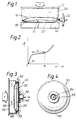
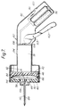
- a sachet 10 is located between upper and lower plates 12, 14 at least one of which is movable.
- the sachet 10 is defined by upper and lower generally rectangular layers 16, 18 of flexible sheet liquid impermeable material which are bonded together around their peripheral margins 20 and the sachet is provided with an outlet 22 which may be controlled by a spring-loaded valve in the manner of an aerosol nozzle.
- the liquid is contained in the unbonded generally rectangular region between the layers 16, 18, ie. within the area bounded by the bonded peripheral margins 20.
- the plate 12 is movable towards and away from the plate 14 by means of an unshown mechanism.
- At least one of the plates (12 in the illustrated embodiment) carries a pad 24 of resiliently deformable material, such as a foam rubber, which contacts the sachet 10 and is dimensioned so as to cover the liquid containing portion of the sachet.
- Compressive loading is applied to the sachet by moving the plate 12 towards the plate 14 which has the effect of compressing the pad 24 which, in turn, will deform in such a way as to conform with the shape of the sachet 10 and translate the force F acting on the plate 12 into pressure applied substantially uniformly over the liquid-containing portion of the sachet.
- valved outlet 22 When the valved outlet 22 is open, as the liquid discharges from the sachet, the sachet-contacting face of the pad 24 will continue to conform to the shape of the liquid containing portion of the sachet as the latter changes.
- the pressure to which the sachet 10 is subjected may vary according to the extent of deformation of the pad so that the rate of dispensing is varied.
- a suitable foam in this instance is a closed cell foam with good elastic properties, eg. an EVA copolymer foam having a density of 50 kg/m 3 such as that manufactured under the brand name "EVAZOTE" EV50.
- EVA copolymer foam having a density of 50 kg/m 3 such as that manufactured under the brand name "EVAZOTE" EV50.
- the material of which the pad 24 is composed is selected so that the pressure applied to the sachet remains substantially constant irrespective of the extent to which the pad is deformed.
- Figure 2 illustrates schematically the characteristics required of a material for this purpose.
- the ordinate d represents the extent to which the pad is deformed from its natural thickness dimension d n and the abscissa P represents the pressure to which the sachet is subjected as a result of such deformation.
- a material suitable for effecting dispensing at a substantially constant rate will exhibit a non-linear curve having a section R over which the rate of change of pressure P with respect to d is reduced compared with other sections of the curve.
- the pressure applied to the sachet may be relatively independent of the manner in which the operating mechanism for effecting foam compression is actuated since the device may be designed so that, irrespective of the force applied to actuate the operating mechanism, the pad is not compressed beyond the extremity d f . In this way, the rate of dispensing fluid from the sachet may be made reasonably uniform for a range of actuating forces applied to the operating mechanism.
- the sachet will be subjected to a substantially constant pressure throughout the dispensing cycle, ie. from full to empty.
- the plateau may not be as well-defined or as shallow; nevertheless, a foam material will be suitable for many applications requiring substantially constant rate dispensing if it exhibits a plateau region in which the force remains reasonably constant over a range of compression/displacement of the foam. Also, many foams when compressed to a given extent will produce a force which decays with time and, especially in the case of applications likely to involve sustained spraying and hence compression of the pad due regard must be given to the decay characteristics of the foam. For many spraying applications, e.g. personal care products such as deodorants and hair sprays, spraying is only sustained for a relatively short time, and hence the decay characteristics of the foam will not affect spraying significantly.
- the present invention may not however be suitable in applications where the foam is to be compressed or pre-compressed for relatively long periods of time because of the decay characteristics of foam materials.
- a suitable foam exhibiting appropriate behaviour for use in many applications of the invention, especially personal care products, is an elastic open cell foam such as polyether foam.
- Figure 2A illustrates typical deformation-v-pressure curves for a number of grades of polyether foam.
- the curves A, B and C respectively correspond to polyether grades ET 14W, ET 22Y and ET 29G supplied by Foam Engineers Limited of High Wycombe, England, each sample being 50 mm thick (uncompressed) and having an area of 130 mm x 50 mm. It will be seen that each sample exhibits a plateau region corresponding to the region R in Figure 2. Thus, by appropriate selection of the grade of polyether, the pressure applied over the plateau region can be varied according to requirements.
- Curve D of Figure 2A corresponds to a composite sample comprising a pad of grade ET 14W in superimposed relation with a pad of grade ET 29G, each pad being 25 mm thick and 130 mm x 50 mm. In this instance, it will be noted that the curve exhibits a first plateau D1 and a second plateau D2.
- a device may be designed which can produce two (or more, depending on the number of superimposed layers within the composite pad) relatively uniform dispensing flow rates, the particular flow rate required being controlled for example by the application of appropriate force by the user so that the composite pad is compressed to an extent within range D1 or D2 as the case may be.
- the device may be provided with some form of indicator to enable the user to judge the pressure necessary to achieve one flow rate or the other.
- the outlet 22 is located at one of the edges of the sachet 10.
- Figures 3 and 4 illustrate a modification in which the sachet 30 has its outlet 36 positioned generally centrally of one of the flexible generally circular, liquid impermeable layers 32, 34.
- the sachet is shown as being of circular configuration although this is not essential, the layers 32, 34 being bonded together around their circumferential edges 35 and the outlet 36 having a flange 38 by means of which it is bonded to the layer 34.
- the device comprises a fixed anvil 40 and a drive plate 42 between which the sachet is located with its outlet 36 received in an opening 44 in the anvil 40 and through which the liquid is discharged.
- a pad 46 of resiliently deformable material which may if desired have a deformation -v- pressure characteristic curve as shown in Figures 2 and 2A is interposed between the sachet and the drive plate 42 and is deformed by movement of the drive plate 42 towards the anvil 40. As in the embodiment of Figure 1, such deformation of the pad 46 results in the application of uniformly distributed compressive loading to the sachet to enable its contents to be dispensed.
- Figures 3 and 4 may be arranged to operate to provide either variable rate dispensing of the liquid or relatively constant rate dispensing, as described in connection with the embodiment of Figure 1.
- the components illustrated conveniently form part of a device including a holder and a user-operable mechanism for actuating relative movement of the plates 12, 14 or the plate 42 and the anvil 40.
- the mechanism may be so designed that operation of a trigger or the like by the user effects opening of the valve of the outlet before compression of the sachet or other flexible walled liquid container.
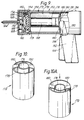
- a cartridge 50 is shown for use with an electrostatic spraying device, the housing 52 of which is illustrated in part.
- the cartridge 50 comprises a casing comprising two parts 54, 56 which are designed to be assembled together to enclose a flexible walled container 58 such as a sachet.
- At least one of the casing parts (preferably both) is provided with a pad 60, 62 of resiliently deformable material, such as a foam material, so that when the casing parts are assembled together in the manner shown in Figure 6, the pads 60, 62 are compressed and thereby apply compressive loading to the sachet 58.
- the casing parts 54, 56 may be hingedly connected at one end 64 so that they can be opened and closed as shown in Figures 5 and 6.
- Means (not shown) may be provided for fastening the parts 54, 56 together in the closed, compressed position; however, fastening means may not be necessary since the two parts can be held in the closed position when inserted into the housing 52 if the latter is dimensioned to receive the cartridge as a close fit.
- the pads are pre-compressed in the manner described with reference to Figure 2, eg.
- the pads may be compressed to the point d f indicated in Figure 2 so that as the pads expand in response to emptying of the sachet, dispensing of the liquid is maintained at a relatively constant pressure.
- the sachet 58 is provided with an outlet 66 incorporating a valve which may operate in the manner of an aerosol valve.
- the outlet of this and the previously described embodiments may comprise a central nozzle 68 depression of which relative to the collar operates an internal valve to open a passage leading from the sachet and through the nozzle 68.
- the device will include a user operable mechanism (not shown) for effecting such depression of the nozzle 68 when desired to allow liquid to be supplied from the sachet to the tip of the nozzle.
- the casing parts 54, 56 at one end are formed with recesses 72 which together form a circular opening for receiving the neck of the outlet 66 when the sachet is inserted into the cartridge 50.
- the casing parts are of semi-cylindrical shape and fit into a cylindrical section of the housing 52.
- the end of the housing is provided with a removable cap assembly (not shown) including an nozzle piece which, when the cartridge is inserted into the housing, registers with the nozzle of the sachet so that liquid can be supplied to the nozzle piece for electrostatic spraying from the latter when the valve associated with the sachet outlet 66 is open.
- Electrostatic potential typically of the order of about 15 to 25 kV is applied to the liquid from an HT generator contained within the housing so that liquid emerging at the tip of the nozzle piece is electrostatically charged and is drawn out into a spray by preponderantly electrostatic forces, the liquid being drawn out by the electrostatic field into ligaments which break up into droplets to form the spray.
- the application of electrostatic potential to the liquid is effected in the embodiment of Figures 5 and 6 by providing one of the casing parts with an electrically conductive path or track 76 which extends from one end of the cartridge to the other to provide electrical connection between the high voltage output of the HT generator and the sachet outlet 66, the latter being of-conductive material and being arranged to make electrical contact with the track 76.
- the embodiment of Figures 5 and 6 may not be suitable for applications where the foam is to be maintained under pre-compression for relatively long periods due to the previously discussed decay characteristics of the foam.
- This embodiment is typically used in "one-shot" spraying applications where the cartridge is closed up to compress the foam, loaded into the device, operated for a relatively short period of time and then disposed of.
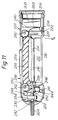
- a hand held electrostatic spraying device in accordance with the invention is in the form of a pistol shaped housing 80 having a hand grip 82 and a generally cylindrical main body portion 84.
- the body portion 84 is fitted with a removable cap 86 which mounts a nozzle piece 88 from which liquid is electrostatically sprayed in use.
- the cap 86 closes the open end of a cavity which receives the liquid container.
- the container is a flexible walled sachet of the form described with reference to Figures 3 and 4 and the same reference numerals are used to identify parts which are common to Figure 7 and Figures 3 and 4.
- the sachet 30 is located between a resilient foam pad 114 adjacent the fixed end wall 40 of the cap 86 and a pad 46 of resiliently deformable material carried by a movable drive plate 42 which is mounted slidably within the cavity and is connected to a piston 91 slidable within the body portion 84.
- Spring means (not shown) is provided to bias the piston to the position shown in which the pad 46 is not compressed or only compressed to a limited extent.
- the piston 91 is constituted by an HT generator for producing from a low voltage source, a high voltage suitable for effecting electrostatic spraying.
- the generator has a high voltage output pole 92 connected to the outlet 66 of the sachet 30 by a flexible lead 94.
- the low voltage source comprises a battery pack 96 accommodated in the hand grip portion 82.
- An earth for the circuit is provided via a resistor 98 and a contact 100 exposed for contact with the user's hand.
- Operation of the device is controlled by a trigger 102 pivoted at 103 and having a cam portion 104 arranged to bear against the adjacent end of the piston/generator 91 so that, as the trigger is squeezed, the piston is displaced to the left as seen in Figure 7 thereby moving the drive plate 42 and compressing the sachet 30.
- the cam 104 is arranged to close a microswitch 106 which completes the circuit to enable the generator to produce a high voltage output at terminal 92 for application to the sachet outlet 66.
- the initial displacement of the drive plate 42 advances the sachet and compresses the pad 114 which may be less stiff than the pad 46, and the nozzle 108 of the sachet outlet 66 is urged against an abutment surface within the nozzle piece 88 causing the nozzle 108 to be depressed relative to the outlet 66 thereby opening the valve of outlet 66.
- initial displacement of the drive plate 42 serves to effect opening of the valve.
- Continued displacement of the drive plate 42 compresses the sachet to effect dispensing of the liquid at a rate governed by the extent to which the trigger is squeezed.
- the liquid emerging through the nozzle 108 enters a passageway 110 extending to the tip of the nozzle piece 88.
- An electrostatic potential is applied to the tip via the terminal 92, lead 94, outlet 66 and the liquid.
- the electrostatic potential gradient existing between the tip and surrounding earthed objects and structures draws out the liquid into a spray of electrically charged droplets which, by virtue of their charge, are attracted to any suitably located earthed target in the vicinity.
- the rate of spraying the liquid can be varied according to the pressure applied by the user to the trigger.
- the foam pad 46 may have the characteristics described with reference to Figures 2 and 2A where the rate of spraying is required to be relatively constant over at least the major part of the range of movement of the trigger lever 102.
- the force exerted on the valved outlet of the sachet during the initial displacement of the drive plate 42 is transmitted via the flange 38 which will be substantially rigid or at least substantially more rigid than the flexible walls of the sachet.
- the flange 38 may be larger than shown in Figure 7 and, in some circumstances, the flange may be substantially co-extensive with one wall of the sachet or the sachet may be fabricated with one wall flexible and a second wall substantially rigid or at least substantially more rigid than the flexible wall, the more rigid wall then being used to transmit force from the drive plate 42 to the valved outlet of the sachet.
- the pad 114 serves to urge the sachet back to the position shown in Figure 7 but it will be appreciated that its function may be achieved by some other form of spring.
- FIG. 7 illustrates one embodiment for implementing such an arrangement.
- certain components are functionally the same as in Figure 7 and such components are identified by the same reference numerals as used in Figure 7.
- the hand grip portion and components accommodated therein of the Figure 8 embodiment may be generally the same as in Figure 7 and have therefore been omitted.
- the sachet is received within a carrier 112 which is slidably mounted within the main body 84 and has a removable cover 115 which provides a surface 40 which contacts one of the major faces of the sachet 30.
- the opposite surface of the sachet is contacted by drive plate 42 through pad 46, the drive plate in this instance being connected to the piston/generator 91 with lost motion in that the piston is slidably received in an enlarged diameter part 116 of a sleeve 118 which is connected to the drive plate 42 and transmits motion from the piston to the drive plate 42 only when the piston has moved into abutment with a shoulder 120 between the enlarged and reduced diameter sections of the sleeve 118.
- the piston 91 and the carrier 112 are linked by a tension spring 122 so that, when the piston is advanced to the left by operation of the trigger, the piston and the carrier (and hence the sachet) move together for a short distance sufficient to operate the valve of the sachet outlet 66.
- the valve is spring-loaded to the closed position and the force exerted by the tension spring 122 is therefore selected to be greater than that exerted by the valve spring.
- the device shown comprises a housing 150 having a handgrip portion 152 provided with a user-operable trigger 154 pivoted at 156 and spring-loaded outwardly of the handgrip portion 152 to an inoperative position by unshown spring means.
- the high voltage generator 158 and microswitch 160 are shown, the remaining circuitry being generally similar to that shown in the embodiment of Figure 7.
- the trigger 154 is arranged to co-operate with the switch 160 which forms part of the low voltage circuitry associated with the high voltage generator 158, the switch being arranged to be operated in response to initial displacement of the trigger 154 from its inoperative position thereby powering the generator 158.
- the handgrip portion or the trigger may be provided with a contact (not shown) exposed for engagement with the hand so as to provide a path to earth in use.
- the housing terminates in a removable cap 162 which may have a snap fit or screw-threaded connection with the housing 150.
- a nozzle 164 projects through the cap 162 and is supplied with liquid from a container 166 within the housing.
- the container is in the form of a sachet having the same design as described with reference to Figures 3 and 4, the valved outlet 168 of the sachet comprising a nozzle portion 170 which fits into the inner end of the nozzle 164.
- the high voltage output of the generator 158 is electrically connected to a conductive part of the sachet outlet 168 so that high voltage is applied in use to the liquid supplied to the nozzle 164.
- the sachet 166 and the generator 158 are received within a carrier 172 which is slidably mounted within the housing 150 for movement towards and away from the cap 162, movement towards the cap occuring in response to squeezing of the trigger 154 and movement in the opposite direction being effected, on release of the trigger, by unshown spring means which may, for instance, act between the cap 162 and a closure 174 located at the forward end of the carrier 172. This spring means may also be effective to return the trigger to its inoperative position in which the switch 160 is open and the generator 158 is de-energised.
- the carrier 172 has a double-sleeved configuration comprising an inner sleeve 176 and an outer sleeve 178 which are united at one end of the carrier by springy webs 180 which permit the inner sleeve to move axially relative to the outer sleeve.
- the carrier is shown in its unstressed condition in which the inner sleeve projects slightly beyond the outer sleeve.
- the carrier is shown in the condition obtained when the inner sleeve is displaced inwardly relative to the outer sleeve, resulting in stressing of the webs 180 which tend to bias the inner sleeve back to the position shown in Figure 10A.
- the inner sleeve 176 forms a housing for the generator 158 and also receives the microswitch 160.
- the generator and the microswitch are securely fixed within the inner sleeve, for example by means of potting resin which may fill the space between the microswitch 160 and the generator 158 and also encapsulate electrical leads (not shown) connecting the generator to the microswitch and to a battery pack (not shown).
- the inner sleeve 176 is shorter in length than the outer sleeve 172 and its forward end has a drive plate 179 secured thereto in spaced relation to closure 174 which closes the forward end of the outer sleeve.
- the closure plate 174 is releasably attached to the carrier and may be screw-threadedly connected to the outer sleeve 178, for instance by screw threads provided on an annular flange 182 on the closure 174 and on the inner periphery of the outer sleeve 178.
- the inwardly presented face of the closure 174 is formed with an annular retaining flange 184 defining a cavity for reception of the sachet 166, the closure 174 being formed with an opening in which the valved outlet 168 of the sachet is engaged so that the outlet is captive with the closure 174.
- a foam pad 186 is interposed between the sachet and the drive plate 179 and may either be secured to the drive plate 179 and received within the cavity defined by the flange 184 or the pad 186 may be separate from the drive plate 179 and housed within the cavity. If desired, a layer of resiliently deformable foam material may also be provided between the sachet and the closure 172 (in similar fashion to the embodiment of Figure 7). Forward movement of the carrier 172 is limited by stops 188 on the cap 162.
- the carrier 172 When the trigger 154 is in its inoperative position, the carrier 172 is shifted to the right, the closure 174 is spaced from the stops 188 and the inner sleeve 176 projects outwardly beyond the outer sleeve 178 as shown in Figure 10A.
- the nozzle portion 170 of the sachet 166 is extended with consequent closure of the valve and the microswitch actuator 190 is also extended so that the microswitch is open and the generator is de-energised.
- the initial displacement of the trigger depresses the microswitch actuator 190 via lever arm 192 to close the switch and energise the generator 158.
- the webs 180 are so designed that, at this point, they provide sufficient spring force to allow continued displacement of the trigger to move the carrier as a unit, by contact between the actuator 190 and the lever arm 192, towards the cap 162 causing the nozzle portion 170 to depress in the manner of an aerosol valve thereby opening the valve to permit supply of liquid from the sachet 166 to the nozzle 164.
- Axial movement of the carrier continues until the closure 174 abuts the stops 188 at which point continued displacement of the trigger overcomes the spring resistance offered by the webs 180 and is translated into inward movement of the inner sleeve 176 relative to the outer sleeve 178 (as shown in Figure 9).
- Such relative movement serves to compress the pad 186 with consequent compression of the sachet 166 and supply of liquid to the nozzle 164 for electrostatic spraying.
- the various components restore to the condition described above prior to operation of the trigger.
- the foam pad may be of the type described with reference to Figures 2 and 2A.
- the pad 186 may be of the composite type described earlier.
- the device may incorporate some form of indicator to enable the user to control the extent of lever displacement in order to achieve the desired spraying rate.
- the device may be provided with a position sensor or sensors for detecting displacement of the trigger from its inoperative position and circuitry for visually indicating when the trigger has been displaced sufficiently to place the foam pad in compression to a level corresponding to each of the plateau regions D1 and D2 shown in Figure 2A.
- displacement of the trigger 154 may be related to the plateau regions by means of light emitting diodes (as depicted by reference numerals 194) provided on the housing so that, by appropriate trigger control, the user can cause a particular LED to be energised according to the rate of spraying required.
- the device may have two levels of operation, corresponding to higher and lower relatively constant spraying rates, and the LED's may be arranged so that one is energised when the trigger is partially depressed to give a lower spraying rate and the other is energised when the trigger is depressed to a greater extent.
- the device incorporates an actuator which eliminates the need for a pistol-type configuration.
- the device comprises a housing 200 of generally tubular configuration terminating at one end in a generally hemispherical portion 202 through which a spraying nozzle 204 projects, the nozzle being fixed relative to the portion 202.
- the portion 202 may be integral with the housing 200 or it may be detachable; for example, it may be connected to the main body of the housing by snap fit or by screw threaded engagement.
- the opposite end of the housing is closed by a removable cap 206 which may also make snap fit or screw threaded engagement with the main body of the housing.
- the removable cap 206 allows access to the interior of the housing for the purpose of fitting/replacement of a low voltage battery source 208 within that end of the housing 200.
- the housing is provided with an opening which is normally closed by a cover 210.
- the cover 210 may be connected to the housing in various ways to allow the cover to be removed, or moved to an open position, so as to allow access to the interior of the housing at a location midway between its ends.
- a high voltage generator 212 is fastened to the cover 210 and, in addition to acting as a source of high voltage (powered by battery source 208), the generator 212 also provides a support surface 214 for a sachet 216 of liquid to be dispensed by the device, eg. a personal care fluid such as a deodorant, fragrance or hair spray.
- the cover 210 in the illustrated embodiment is hingedly connected to the main body of the housing 200 by hinge connection 218 so that the cover can be moved (together with the generator 212) in the direction A from the closed position shown to an open position in which the sachet 216 is exposed for removal and replacement.
- one end 220 of the cover engages with the main body of the housing and may be fastened thereto by a releasable catch or the like (not shown).
- the outlet of the sachet 216 is connected by flexible pipe 226 to a valve assembly 230 of the aerosol valve type.
- the valve assembly 230 includes a nozzle portion 232 which is inserted into the inner end of the nozzle in a manner similar to the embodiments of Figures 7 to 9 such that axial displacement of the collar portion 234 relative to the nozzle portion 232 displaces the latter inwardly of the collar against the action of outward spring biassing and is effective to open the valve to permit feed of liquid from the sachet 216 through pipe 226 to the nozzle 204 for spraying from the tip thereof.
- the sachet 216 is conveniently manufactured with an outlet which is sealed by a foil through which the pipe 226 can be inserted in order to communicate the interior of the sachet with the nozzle 204.
- the housing 200 incorporates an actuator 236 which is displaceable laterally of the longitudinal axis of the housing so as to apply compression to the sachet 216 through the agency of a foam pad 238.
- the actuator 236 is mounted by pairs of slides 240 disposed within the housing 200 (only one of each pair being shown) and having slots with which guide pins 242 carried by the actuator 236 are engaged.
- the actuator 236 can be displaced from the inoperative position shown towards the generator 212 thereby compressing the foam pad 238 and compressively loading the sachet 216.
- the resilience of the foam pad 238 may be sufficient to restore the actuator 236 to the position shown when the squeezing action is discontinued or a separate spring means be arranged to bias the actuator 236 to the inoperative position.
- the actuator 236 is arranged to cooperate with a cam follower 244 mounted within the housing by pivot pin 248 comprising a pair of lobes 246 (only one of which is shown) which straddle the pipe 226, the cam follower 244 being spring-loaded to the position shown by unshown spring means.
- cam portion 250 contacts the follower 246 and deflects it clockwise so as to displace the collar 234 of the valve assembly 230 relative to the nozzle portion 204 thereby opening the valve to permit dispensing of liquid from the sachet 216.
- the degree of lost motion to be taken up before the cam portion 250 contacts the cam follower 246 may be such that the foam pad 238 is compressed to a point corresponding to a plateau region as previously described in connection with Figures 2 and 2A.
- the high voltage output of the generator 212 is connected to the valve assembly by lead 252 so that electrical potential is applied to the liquid at that point in its feed path.
- the liquid emerging at the tip of the nozzle 204 is electrically charged and a spray of fine droplets is produced as a result of the liquid being drawn out, preponderantly by the electrical field gradient existing between the nozzle tip and the surroundings (usually at earth potential), into ligaments which thereafter break up into electrically charged droplets.
- Switching on of the generator 212 is effected by a switch 254 located on the actuator 236 and so arranged that the switch energises the low voltage circuitry to power the generator in response to the squeezing action applied by the user.
- the switch 254 may for example be in the form of a membrane switch and is connected to the battery source by flexible lead 258 and to the low voltage input side of the generator 212 by a flexible lead (not shown) which will be connected to the generator through a contact set such as that depicted by reference numerals 222, 224.
- An earth return path may be provided by contact of the users hand with a suitable contact on the actuator.
- the application of a squeezing action to the housing 200 when held in the hand, displaces the actuator 236 to open the valve assembly 230 and compress the sachet 216 and also operates the switch 254 to power the generator 212 so that high voltage is applied to the liquid fed to the nozzle 204 as a result of compression of the sachet.
- the empty sachet can be readily replaced by a fresh one by opening cover 210, pulling the sachet away from the pipe 226, connecting the pipe 226 to the fresh sachet by using it to pierce through the foil seal at the sachet outlet, positioning the fresh sachet in the housing and closing the cover 210.
Landscapes
- Engineering & Computer Science (AREA)
- Mechanical Engineering (AREA)
- Electrostatic Spraying Apparatus (AREA)
- Nozzles (AREA)
- Containers And Packaging Bodies Having A Special Means To Remove Contents (AREA)
- Coating Apparatus (AREA)
- Electrical Discharge Machining, Electrochemical Machining, And Combined Machining (AREA)
- Extraction Or Liquid Replacement (AREA)
- Acyclic And Carbocyclic Compounds In Medicinal Compositions (AREA)
- Application Of Or Painting With Fluid Materials (AREA)
Claims (27)
- Vorrichtung zum elektrostatischen Sprühen von Fluids, umfassend ein Gehäuse (80; 150; 200) für die Aufnahme eines flexiblen fluidhaltigen Behälters (30; 58; 166; 216), wobei der Behälter von dem Typ ist, der seinen Inhalt in Reaktion darauf ausgibt, daß er zusammengedrückt wird, eine Düse (88; 164; 204), aus der das Fluid beim Gebrauch gesprüht werden soll, ein Mittel (42, 46; 179, 186; 236, 238) zum Zusammendrücken des Behälters, um Fluid zur Düse zu führen, und ein Hochspannungsmittel (91; 158; 208) zum Anlegen von elektrostatischem Potential an das Fluid, so daß das Fluid aus der Vorrichtung in der Form eines elektrisch geladenen Sprays austritt, wobei das genannte Mittel zum Zusammendrücken des Behälters folgendes umfaßt: ein Kissen (46; 186; 238) aus elastisch verformbarem Material, das an dem Behälter anliegt, und ein Mittel (42; 179; 236) zum Verformen des genannten Materials, um den Behälter einer Kompressionslast auszusetzen.
- Vorrichtung nach Anspruch 1, bei der das elastisch verformbare Material eine Kompressions-/Verformungskurve mit einer Plateauregion hat, über die der von dem Kissen ausgeübte Druck in einem geringeren Maß pro Einheitsverformung der Kissendicke variiert als über benachbarten Regionen der Kurve, und bei der das Verformungsmittel die Aufgabe hat, das Kissen über einen Verformungsbereich zusammenzudrücken, der die genannte Plateauregion einschließt.
- Vorrichtung nach Anspruch 2, bei der das Verformungsmittel so angeordnet ist, daß es das Kissen so vorkomprimiert, daß das Kissen in einem Maß verformt wird, das einem Extremwert der genannten Plateauregion entspricht oder sich diesem nähert, so daß sich das Kissen mit dem Leeren des Behälters ausdehnt, aber wenigstens so lange innerhalb der genannten Plateauregion in einem Maß zusammengedrückt bleibt, bis der Behälter fast leer ist.
- Vorrichtung nach Anspruch 3, bei der ein Kasten (50) vorgesehen ist, der ein Paar Kastenteile (54, 56) umfaßt, die zusammengebracht werden können, um den Behälter (58) dazwischen einzuschließen, wobei wenigstens eines der Kastenteile mit einem genannten Kissen (60, 62) aus elastisch verformbarem Material versehen ist, wobei das/die Kissen beim Einschließen des Behälters innerhalb der Kastenteile vorkomprimiert wird/werden.
- Vorrichtung nach Anspruch 1 oder 2, bei der das Verformungsmittel ein vom Benutzer verschiebbares Element (102; 154; 236) umfaßt, um ein Zusammendrücken des Kissens zu bewirken.
- Vorrichtung nach Anspruch 5 in Abhängigkeit von Anspruch 1, bei der das vom Benutzer verschiebbare Element steuerbar ist, um den Verformungsgrad des Kissens zu variieren.
- Vorrichtung nach Anspruch 5 in Abhängigkeit von Anspruch 2, bei der das genannte Element einen Verschiebungsbereich aufweist, so daß über wenigstens einen Hauptteil seines Verschiebungsbereiches das Kissen innerhalb der genannten Plateauregion zusammengedrückt bleibt.
- Vorrichtung nach einem der Ansprüche 2 bis 4 oder der Ansprüche 5 bis 7 in Abhängigkeit von Anspruch 2, bei der das elastisch verformbare Material ein Schaumstoffmaterial mit einer offenzelligen Struktur umfaßt.
- Vorrichtung nach einem der Ansprüche 1 bis 8, bei der das Kissen beim Gebrauch direkt an dem Behälter anliegt.
- In Kombination eine Vorrichtung nach einem der Ansprüche 1 bis 6 und einen zusammendrückbaren Behälter, der in dem Gehäuse plaziert ist.
- Kombination nach Anspruch 10, bei der der Behälter einen Beutel (30; 58; 166; 216) mit einem ventilgesteuerten Ausgang umfaßt.
- Kombination nach Anspruch 10 oder 11, bei der der Behälter wenigstens eine flexible Wand umfaßt.
- Vorrichtung nach Anspruch 1, bei der der Behälter einen Beutel (30; 58; 166; 216) mit einem ventilgesteuerten Ausgang (36; 66; 168; 234) umfaßt, der mit der Düse verbunden ist, wobei das genannte Mittel zum Zusammendrücken des Behälters folgendes umfaßt: ein an dem Gehäuse befestigtes, vom Benutzer zu betätigendes Element und ein Mittel zum Umsetzen der Betätigung des genannten Elementes in ein Zusammendrücken des Beutels, wobei das genannte Umsetzmittel eine Antriebsplatte und ein Kissen aus elastisch verformbarem Material umfaßt, das zwischen der Antriebsplatte und dem Beutel liegt, so daß die Betätigung des genannten Elementes eine Verschiebung der Antriebsplatte bewirkt, so daß das Kissen verformt und eine Kompressionslast durch die Wirkung des Kissens auf den Beutel aufgebracht wird.
- Vorrichtung oder Kombination nach Anspruch 11, 12 oder 13, bei der der Beutel ein Paar gegenüberliegender Wände (16, 18) umfaßt, von denen wenigstens eine flexibel ist und die um die Peripherie des Beutels aneinandergefügt sind, wobei der Ausgang in einer ersten der genannten Wände vorgesehen ist.
- Vorrichtung oder Kombination nach Anspruch 14 in Abhängigkeit von Anspruch 13, bei der der Beutel so plaziert ist, daß die zweite der genannten Wände für einen Eingriff mit dem genannten Kissen dargeboten wird.
- Vorrichtung oder Kombination nach Anspruch 13, Anspruch 14, in Abhängigkeit von Anspruch 13, oder Anspruch 15, bei der der ventilgesteuerte Ausgang des Beutels einen Kragen (66) und ein bewegliches Düsenelement (108) umfaßt, so daß das den Ausgang des Beutels steuernde Ventil in Reaktion auf die Bewegung des Düsenelementes relativ zu dem Kragen geöffnet wird, wobei das genannte Umsetzmittel ein Leerlaufmittel enthält, das so angeordnet ist, daß eine anfängliche Betätigung des vom Benutzer zu betätigenden Elementes eine Umsetzbewegung des Beutels und des Kragens relativ zum Düsenelement des Beutels bewirkt, um das Ventil zu öffnen, und danach eine fortgesetzte Betätigung des vom Benutzer zu betätigenden Elementes wirksam wird, um den Beutel zusammenzudrücken, um die Zufuhr von Fluid zur Vorrichtungsdüse zu bewirken.
- Vorrichtung nach einem der Ansprüche 13 bis 16, bei der das genannte Hochspannungsmittel an dem Beutelausgang angeschlossen ist, wodurch das hohe Potential durch die Wirkung des Beutelausgangs an das Fluid angelegt wird.
- Vorrichtung zum Ausgeben von Fluids, umfassend ein Gehäuse (80; 150; 200) für die Aufnahme eines flexiblen fluidhaltigen Behälters (30; 58; 166; 216), wobei der Behälter von dem Typ ist, der seinen Inhalt in Reaktion darauf ausgibt, daß er zusammengedrückt wird, und ein Mittel (42, 46; 179, 186; 236, 238) zum Zusammendrücken des Behälters, um Fluid zu einem Ausgabeausgang der Vorrichtung zu führen, wobei das genannte Mittel zum Zusammendrücken des Behälters ein vom Benutzer verschiebbares Element (102; 154; 236) umfaßt, wobei die genannte Vorrichtung dadurch gekennzeichnet ist, daß das genannte Kompressionsmittel ferner ein Mittel für eine nichtlineare Umsetzung der Verschiebung in Kompressionskraft umfaßt, wobei eine Kompressionskraft-/Verschiebungskurve eine Plateauregion aufweist, über die die pro Einheitsverschiebung erzeugte Kompressionskraft im Vergleich zu benachbarten Regionen relativ konstant ist, so daß eine relativ konstante Ausgaberate erzielt werden kann.
- Vorrichtung nach Anspruch 18, ferner umfassend ein Hochspannungsmittel zum Anlegen eines elektrostatischen Potentials an das Fluid, so daß das Fluid aus der Vorrichtung in der Form eines elektrisch geladenen Sprays austritt.
- Vorrichtung nach Anspruch 18 oder 19, bei der das vom Benutzer verschiebbare Element einen vorbestimmten Verschiebungsbereich aufweist und bei der die Anordnung derart ist, daß das Umsetzmittel innerhalb der genannten Plateauregion über wenigstens einen Hauptteil der Verschiebung des genannten Elementes über den genannten vorbestimmten Bereich wirksam ist.
- Vorrichtung nach Anspruch 20, bei der das Umsetzmittel eine Kompressionskraft-/Verschiebungskurve mit wenigstens zwei Plateauregionen wie zuvor erwähnt aufweist, so daß wenigstens zwei relativ konstante Ausgaberaten erzielt werden können.
- Vorrichtung nach Anspruch 21, umfassend ein Mittel zum Bereitstellen eines Hinweises, der die Verschiebung des genannten vom Benutzer zu betätigenden Elementes und die Sprührate in Beziehung setzt, so daß der Benutzer das genannte Element steuern kann, um eine ausgewählte relativ konstante Ausgaberate zu erhalten.
- Vorrichtung nach einem der Ansprüche 1 bis 22, bei der das genannte Kompressionsmittel den Behälter in bezug auf den Ausgang des Behälters axial zusammendrückt.
- Vorrichtung nach einem der Ansprüche 1 bis 23, bei der das genannte Kompressionsmittel den Behälter in bezug auf den Ausgang des Behälters transversal zusammendrückt.
- Vorrichtung nach Anspruch 24, bei der das Gehäuse eine allgemein zylindrische Konfiguration hat, ohne einen lateral vorstehenden Handgriffabschnitt, und so ausgestaltet ist, daß sie in der Hand gehalten werden kann, indem ihre Peripherie von der Hand umschlossen wird.
- Vorrichtung nach Anspruch 23 oder 24, bei der das Gehäuse (200) eine längliche Konfiguration hat, die für den Handgebrauch geeignet ist, und einen Hohlraum für die Aufnahme des Behälters aufweist, so daß größere Flächen des Behälters im wesentlichen axial vom Gehäuse wegverlaufen, wobei das Kompressionsmittel ein vom Benutzer zu betätigendes Stellglied (236) enthält, das von der Längsachse des Gehäuses transversal verschiebbar ist, um eine Kompressionsbelastung des Behälters zu bewirken.
- Behälter mit einer elektrostatischen Sprühvorrichtung nach einem der Ansprüche 1 bis 9 oder der Ansprüche 13 bis 17 oder 19 bis 26, wobei der genannte Behälter Flüssigkeit enthält, die zum elektrostatischen Sprühen geeignet ist, und mit einem Mittel zum Anlegen von Hochspannung an die Flüssigkeit versehen ist, wobei der genannte Behälter wenigstens eine flexible Wand aufweist, so daß er, wenn er mit der genannten Vorrichtung zusammengefügt ist, durch das genannte Kompressionsmittel der Vorrichtung zusammengedrückt werden kann, um eine Ausgabe der genannten Flüssigkeit zu bewirken.
Priority Applications (22)
| Application Number | Priority Date | Filing Date | Title |
|---|---|---|---|
| AT00126021T ATE309051T1 (de) | 1991-03-01 | 1992-02-24 | Flüssigkeitszerstäubung |
| EP00126021A EP1084758B1 (de) | 1991-03-01 | 1992-02-24 | Flüssigkeitszerstäubung |
| DE69233562T DE69233562T2 (de) | 1991-03-01 | 1992-02-24 | Flüssigkeitszerstäubung |
| DE69231870T DE69231870T2 (de) | 1991-03-01 | 1992-02-24 | Sprühen von Flüssigkeiten |
| EP92301530A EP0501725B1 (de) | 1991-03-01 | 1992-02-24 | Sprühen von Flüssigkeiten |
| ES00126021T ES2253174T3 (es) | 1991-03-01 | 1992-02-24 | Pulverizacion de liquidos. |
| PT92301530T PT501725E (pt) | 1991-03-01 | 1992-02-24 | Pulverizacao de liquidos |
| DK92301530T DK0501725T3 (da) | 1991-03-01 | 1992-02-24 | Sprøjtning af væsker |
| AT92301530T ATE202014T1 (de) | 1991-03-01 | 1992-02-24 | Sprühen von flüssigkeiten |
| ES92301530T ES2158844T3 (es) | 1991-03-01 | 1992-02-24 | Pulverizacion de liquidos. |
| AU11246/92A AU658859B2 (en) | 1991-03-01 | 1992-02-26 | Spraying of liquids |
| CA002062064A CA2062064C (en) | 1991-03-01 | 1992-02-28 | Spraying of liquids |
| US07/843,078 US5292067A (en) | 1991-03-01 | 1992-03-02 | Apparatus and method for ligament mode electrostatic spraying |
| JP4093934A JPH05104035A (ja) | 1991-03-01 | 1992-03-02 | 液体噴霧装置 |
| ZA922475A ZA922475B (en) | 1991-03-01 | 1992-04-03 | Spraying of liquids. |
| TW081103329A TW218360B (de) | 1991-10-15 | 1992-04-28 | |
| KR1019920013363A KR100229943B1 (ko) | 1990-10-26 | 1992-07-25 | 액체 분무방법 및 그 장치 |
| US08/118,247 US5490633A (en) | 1991-03-01 | 1993-09-09 | Apparatus for ligament made electrostatic spraying |
| AU20538/95A AU671054B2 (en) | 1991-03-01 | 1995-06-07 | Spraying of liquids |
| HK98112417.3A HK1011310B (en) | 1991-03-01 | 1998-11-27 | Spraying of liquids |
| HK01106512.5A HK1035876B (en) | 1991-03-01 | 1998-11-27 | Spraying of liquids |
| GR20010401150T GR3036300T3 (en) | 1991-03-01 | 2001-07-31 | Spraying of liquids. |
Applications Claiming Priority (2)
| Application Number | Priority Date | Filing Date | Title |
|---|---|---|---|
| GB909023339A GB9023339D0 (en) | 1990-10-26 | 1990-10-26 | Dispensing of fluids |
| GB9023339 | 1990-10-26 |
Publications (2)
| Publication Number | Publication Date |
|---|---|
| EP0482814A1 EP0482814A1 (de) | 1992-04-29 |
| EP0482814B1 true EP0482814B1 (de) | 1999-04-21 |
Family
ID=10684406
Family Applications (1)
| Application Number | Title | Priority Date | Filing Date |
|---|---|---|---|
| EP91309472A Expired - Lifetime EP0482814B1 (de) | 1990-10-26 | 1991-10-15 | Flüssigkeitsabgabevorrichtung mit konstantem Austrag |
Country Status (11)
| Country | Link |
|---|---|
| US (1) | US5221050A (de) |
| EP (1) | EP0482814B1 (de) |
| JP (1) | JP3307965B2 (de) |
| KR (1) | KR100229943B1 (de) |
| AT (1) | ATE179097T1 (de) |
| CA (1) | CA2054224C (de) |
| DE (1) | DE69131153T2 (de) |
| DK (1) | DK0482814T3 (de) |
| ES (1) | ES2133280T3 (de) |
| GB (2) | GB9023339D0 (de) |
| GR (1) | GR3030738T3 (de) |
Families Citing this family (57)
| Publication number | Priority date | Publication date | Assignee | Title |
|---|---|---|---|---|
| AU9089591A (en) * | 1990-12-17 | 1992-07-22 | Minnesota Mining And Manufacturing Company | Inhaler |
| JPH07501972A (ja) * | 1991-08-13 | 1995-03-02 | ザ・モーガン・クルーシブル・カンパニー・ピーエルシー | 噴霧ガン |
| GB9212974D0 (en) * | 1992-06-18 | 1992-07-29 | Morgan Crucible Co | Spray gun |
| GB9202149D0 (en) * | 1992-01-31 | 1992-03-18 | Unilever Plc | Pressure fluid dispensers |
| GB9202150D0 (en) * | 1992-01-31 | 1992-03-18 | Unilever Plc | Pump dispensers |
| BR9306569A (pt) * | 1992-06-18 | 1999-01-12 | Morgan Crucible Co | Pistola de pulverização |
| AU4348193A (en) * | 1992-06-18 | 1994-01-04 | Morgan Crucible Company Plc, The | Spray gun |
| US5353962A (en) * | 1993-01-19 | 1994-10-11 | Williams Dispenser Corporation | Dispenser with an energy storage member |
| ATE199128T1 (de) * | 1993-11-16 | 2001-02-15 | Procter & Gamble | Sprühvorrichtung |
| US5427125A (en) * | 1994-03-08 | 1995-06-27 | Mortech Technologies Of North America Ltd. | Lavatories and the like cleaning appliance |
| GB9418039D0 (en) * | 1994-09-07 | 1994-10-26 | Reckitt & Colmann Prod Ltd | Electrostatic spraying device |
| GB9604329D0 (en) * | 1996-02-29 | 1996-05-01 | Ici Plc | Electrostatic spraying |
| US6375094B1 (en) | 1997-08-29 | 2002-04-23 | Nordson Corporation | Spray gun handle and trigger mechanism |
| EP0967016B1 (de) * | 1998-01-13 | 2004-11-10 | Abb K.K. | Beschichtungsvorrichtung mit einem drehenden sprühkopf |
| KR20060109356A (ko) * | 1999-08-03 | 2006-10-19 | 화이자 헬스 에이비 | 액체 분출 방법 및 액체 분출 장치 |
| US6730066B1 (en) * | 1999-08-03 | 2004-05-04 | Pharmacia Ab | Liquid delivery container |
| USD443728S1 (en) | 1999-08-18 | 2001-06-12 | The Procter & Gamble Company | Sprayer cartridge |
| USD433193S (en) * | 1999-08-18 | 2000-10-31 | The Procter & Gamble Company | Sprayer |
| US6311903B1 (en) | 1999-08-18 | 2001-11-06 | The Procter & Gamble Company | Hand-held electrostatic sprayer apparatus |
| US7712687B2 (en) * | 1999-08-18 | 2010-05-11 | The Procter & Gamble Company | Electrostatic spray device |
| US6814318B2 (en) | 1999-08-18 | 2004-11-09 | The Procter & Gamble Company | Disposable cartridge for electrostatic spray device |
| USD437978S1 (en) | 1999-08-18 | 2001-02-20 | The Procter & Gamble Company | Sprayer |
| US6318647B1 (en) | 1999-08-18 | 2001-11-20 | The Procter & Gamble Company | Disposable cartridge for use in a hand-held electrostatic sprayer apparatus |
| USD464564S1 (en) | 1999-08-18 | 2002-10-22 | The Procter & Gamble Company | Sprayer cartridge |
| US6682004B2 (en) | 1999-08-18 | 2004-01-27 | The Procter & Gamble Company | Electrostatic spray device |
| US7152817B2 (en) * | 1999-08-18 | 2006-12-26 | The Procter & Gamble Company | Electrostatic spray device |
| US6502766B1 (en) | 2000-07-24 | 2003-01-07 | The Procter & Gamble Company | Liquid sprayers |
| US6752330B2 (en) | 2000-07-24 | 2004-06-22 | The Procter & Gamble Company | Liquid sprayers |
| US6868851B2 (en) * | 2002-01-31 | 2005-03-22 | Instrumentarium Corp. | Liquid reservoir for nebulizer |
| US20030160105A1 (en) * | 2002-02-22 | 2003-08-28 | Kelly Arnold J. | Methods and apparatus for dispersing a conductive fluent material |
| CN100408200C (zh) * | 2003-09-12 | 2008-08-06 | 托利尼迪工业株式会社 | 涂敷机 |
| CA2539153A1 (en) * | 2003-09-22 | 2005-04-07 | James F. Mank | Press for removing supernatant from a flexible vessel |
| WO2005075093A1 (en) * | 2004-02-09 | 2005-08-18 | Matsushita Electric Works, Ltd. | Electrostatic spraying device |
| CN100444967C (zh) * | 2004-02-09 | 2008-12-24 | 松下电工株式会社 | 静电喷涂设备 |
| WO2005075091A1 (en) * | 2004-02-09 | 2005-08-18 | Matsushita Electric Works, Ltd. | Electrostatic spraying device |
| WO2005075090A1 (en) * | 2004-02-09 | 2005-08-18 | Matsushita Electric Works, Ltd. | Electrostatic spraying device |
| KR100765492B1 (ko) * | 2006-08-28 | 2007-10-10 | 마츠시다 덴코 가부시키가이샤 | 정전 스프레이 장치 |
| GB0625127D0 (en) * | 2006-12-18 | 2007-01-24 | Ici Ltd | Electrostatic paint spray device |
| KR100875719B1 (ko) * | 2007-02-23 | 2008-12-24 | 이희영 | 유체 분사 장치 |
| JP2008296132A (ja) * | 2007-05-31 | 2008-12-11 | Daikin Ind Ltd | 静電噴霧装置 |
| JP2008296143A (ja) * | 2007-05-31 | 2008-12-11 | Daikin Ind Ltd | 流体搬送装置及び静電噴霧装置 |
| JP2009172488A (ja) | 2008-01-22 | 2009-08-06 | Daikin Ind Ltd | 静電噴霧装置 |
| JP2009172483A (ja) * | 2008-01-22 | 2009-08-06 | Daikin Ind Ltd | 静電噴霧装置 |
| JP5386826B2 (ja) * | 2008-01-22 | 2014-01-15 | ダイキン工業株式会社 | 静電噴霧装置 |
| US8622324B2 (en) * | 2011-10-14 | 2014-01-07 | Zyw Corporation | VOC-less electrostatic fluid dispensing apparatus |
| US9586728B2 (en) * | 2012-10-25 | 2017-03-07 | Sca Hygiene Products Ab | Dispensing system with the means for detecting liquid level and a collapsible container for such a system |
| US8985397B2 (en) * | 2013-03-08 | 2015-03-24 | Guardian 8 Corporation | Systems and methods for spraying an aerosol |
| EP3046676B1 (de) * | 2013-09-20 | 2018-07-25 | Spraying Systems Co. | Elektrostatische sprühdüsenanordnung |
| FR3015920B1 (fr) * | 2013-12-26 | 2016-02-05 | Plastic Omnium Cie | Procede pour realiser une piece en matiere plastique ayant une ame en mousse |
| US9493933B2 (en) * | 2014-08-07 | 2016-11-15 | Brasscraft Manufacturing Company | Pedestal strainer for a sink drain |
| EP4292629A3 (de) | 2014-09-04 | 2024-03-20 | Octet Medical, Inc. | Elektrostatisches flüssigkeitsabgabesystem |
| US9226617B1 (en) * | 2015-02-19 | 2016-01-05 | John Ondracek | Bottle with heated spout |
| CN113798075A (zh) | 2015-12-21 | 2021-12-17 | 胜利创新公司 | 静电流体输送背包系统 |
| CN106583176B (zh) * | 2016-12-29 | 2022-11-15 | 北京东方诚国际钢结构工程有限公司 | 一种涂胶机胶桶设备及其使用方法 |
| KR102516650B1 (ko) * | 2017-04-21 | 2023-04-03 | 요트. 바그너 게엠베하 | 분무기용 액체 탱크 |
| JP6967567B2 (ja) * | 2018-10-17 | 2021-11-17 | 花王株式会社 | 静電紡糸装置 |
| US11247459B2 (en) * | 2019-07-22 | 2022-02-15 | Canon Kabushiki Kaisha | Liquid charging apparatus, liquid charging method, and manufacturing method |
Family Cites Families (10)
| Publication number | Priority date | Publication date | Assignee | Title |
|---|---|---|---|---|
| FR1542898A (fr) * | Atomiseur sanitaire | |||
| US2159894A (en) * | 1937-02-04 | 1939-05-23 | Posie L Hines | Sprayer |
| US2629516A (en) * | 1951-10-02 | 1953-02-24 | Lucretia E Badham | Combination liquid pistol and spotlight |
| FR2407168A1 (fr) * | 1977-10-28 | 1979-05-25 | Degroote Pierre | Dispositif permettant le vidage total du liquide contenu dans un recipient souple et emballage muni de ce dispositif |
| BE868443A (fr) * | 1978-06-26 | 1978-12-27 | Staar Dev Cy S A | Systeme de conditionnement/distributeur pour doses uniques |
| JPS5943786B2 (ja) * | 1979-03-30 | 1984-10-24 | パナフアコム株式会社 | 記憶装置のアクセス方式 |
| GB2127494B (en) * | 1982-08-18 | 1986-02-26 | Kwaun Peng Koh | Portable dispenser for semi-solids |
| GB8305816D0 (en) * | 1983-03-02 | 1983-04-07 | Ici Plc | Containers |
| US4907727A (en) * | 1988-10-31 | 1990-03-13 | Illinois Tool Works, Inc. | Dispensing device having improved plunger assemblies |
| US5105984A (en) * | 1990-06-27 | 1992-04-21 | Kazimir Charles E | Paste tube dispenser and method for making same |
-
1990
- 1990-10-26 GB GB909023339A patent/GB9023339D0/en active Pending
-
1991
- 1991-10-15 AT AT91309472T patent/ATE179097T1/de not_active IP Right Cessation
- 1991-10-15 ES ES91309472T patent/ES2133280T3/es not_active Expired - Lifetime
- 1991-10-15 EP EP91309472A patent/EP0482814B1/de not_active Expired - Lifetime
- 1991-10-15 DE DE69131153T patent/DE69131153T2/de not_active Expired - Fee Related
- 1991-10-15 DK DK91309472T patent/DK0482814T3/da active
- 1991-10-23 JP JP27562791A patent/JP3307965B2/ja not_active Expired - Lifetime
- 1991-10-24 US US07/781,316 patent/US5221050A/en not_active Expired - Lifetime
- 1991-10-25 CA CA002054224A patent/CA2054224C/en not_active Expired - Fee Related
-
1992
- 1992-03-31 GB GB929206998A patent/GB9206998D0/en active Pending
- 1992-07-25 KR KR1019920013363A patent/KR100229943B1/ko not_active Expired - Fee Related
-
1999
- 1999-07-12 GR GR990401817T patent/GR3030738T3/el unknown
Also Published As
| Publication number | Publication date |
|---|---|
| DE69131153T2 (de) | 1999-11-18 |
| CA2054224C (en) | 2001-09-11 |
| CA2054224A1 (en) | 1992-04-27 |
| JPH05138081A (ja) | 1993-06-01 |
| GB9023339D0 (en) | 1990-12-05 |
| HK1011304A1 (en) | 1999-07-09 |
| GR3030738T3 (en) | 1999-11-30 |
| ATE179097T1 (de) | 1999-05-15 |
| DE69131153D1 (de) | 1999-05-27 |
| DK0482814T3 (da) | 1999-11-01 |
| KR100229943B1 (ko) | 1999-11-15 |
| JP3307965B2 (ja) | 2002-07-29 |
| GB9206998D0 (en) | 1992-05-13 |
| EP0482814A1 (de) | 1992-04-29 |
| ES2133280T3 (es) | 1999-09-16 |
| KR930007511A (ko) | 1993-05-20 |
| US5221050A (en) | 1993-06-22 |
Similar Documents
| Publication | Publication Date | Title |
|---|---|---|
| EP0482814B1 (de) | Flüssigkeitsabgabevorrichtung mit konstantem Austrag | |
| CA2062064C (en) | Spraying of liquids | |
| US3335913A (en) | Pressure dispensing device for fluid material | |
| US4244525A (en) | Writing instrument with refillable scent dispenser | |
| US4067499A (en) | Non-aerosol continuous spray dispenser | |
| US3471065A (en) | Liquid spraying device | |
| US5261571A (en) | Dosing dispenser | |
| JPH06506628A (ja) | 静電スプレーガン | |
| US9114415B2 (en) | System and method for dispensing sprayable material | |
| CA1178562A (en) | Device for dispensing a single-component or multi- component substance | |
| GB2041249A (en) | Atomizer | |
| US5411211A (en) | Spray gun | |
| US5316221A (en) | Fluid dispenser having deformable container pressurized by leaf springs | |
| KR960006352B1 (ko) | 유체 디스펜서 | |
| US5400975A (en) | Actuators for electrostatically charged aerosol spray systems | |
| HK1011304B (en) | Fluid dispenser with uniform rate of dispensing | |
| US4948927A (en) | Visco-elastic delayed actuator and system | |
| CN101909762A (zh) | 静电喷雾装置 | |
| USRE30566E (en) | Rechargeable sprayer | |
| HK1011310B (en) | Spraying of liquids | |
| HK1035876B (en) | Spraying of liquids | |
| HU213355B (en) | Packaging device for dispersion and pression of several chemicals | |
| WO1994026420A1 (en) | Fluid delivery valve |
Legal Events
| Date | Code | Title | Description |
|---|---|---|---|
| PUAI | Public reference made under article 153(3) epc to a published international application that has entered the european phase |
Free format text: ORIGINAL CODE: 0009012 |
|
| AK | Designated contracting states |
Kind code of ref document: A1 Designated state(s): AT BE CH DE DK ES FR GB GR IT LI LU NL SE |
|
| 17P | Request for examination filed |
Effective date: 19920929 |
|
| 17Q | First examination report despatched |
Effective date: 19931119 |
|
| RIN1 | Information on inventor provided before grant (corrected) |
Inventor name: NOAKES, TIMOTHY JAMES Inventor name: JEFFERIES,ANDREW Inventor name: GREEN, MICHAEL LESLIE |
|
| GRAG | Despatch of communication of intention to grant |
Free format text: ORIGINAL CODE: EPIDOS AGRA |
|
| RAP1 | Party data changed (applicant data changed or rights of an application transferred) |
Owner name: THE PROCTER & GAMBLE COMPANY |
|
| GRAG | Despatch of communication of intention to grant |
Free format text: ORIGINAL CODE: EPIDOS AGRA |
|
| GRAH | Despatch of communication of intention to grant a patent |
Free format text: ORIGINAL CODE: EPIDOS IGRA |
|
| GRAH | Despatch of communication of intention to grant a patent |
Free format text: ORIGINAL CODE: EPIDOS IGRA |
|
| GRAA | (expected) grant |
Free format text: ORIGINAL CODE: 0009210 |
|
| AK | Designated contracting states |
Kind code of ref document: B1 Designated state(s): AT BE CH DE DK ES FR GB GR IT LI LU NL SE |
|
| REF | Corresponds to: |
Ref document number: 179097 Country of ref document: AT Date of ref document: 19990515 Kind code of ref document: T |
|
| REG | Reference to a national code |
Ref country code: CH Ref legal event code: EP |
|
| REF | Corresponds to: |
Ref document number: 69131153 Country of ref document: DE Date of ref document: 19990527 |
|
| REG | Reference to a national code |
Ref country code: CH Ref legal event code: NV Representative=s name: RITSCHER & SEIFERT |
|
| ET | Fr: translation filed | ||
| REG | Reference to a national code |
Ref country code: ES Ref legal event code: FG2A Ref document number: 2133280 Country of ref document: ES Kind code of ref document: T3 |
|
| REG | Reference to a national code |
Ref country code: DK Ref legal event code: T3 |
|
| PLBE | No opposition filed within time limit |
Free format text: ORIGINAL CODE: 0009261 |
|
| STAA | Information on the status of an ep patent application or granted ep patent |
Free format text: STATUS: NO OPPOSITION FILED WITHIN TIME LIMIT |
|
| 26N | No opposition filed | ||
| REG | Reference to a national code |
Ref country code: GB Ref legal event code: IF02 |
|
| PGFP | Annual fee paid to national office [announced via postgrant information from national office to epo] |
Ref country code: AT Payment date: 20050914 Year of fee payment: 15 |
|
| PGFP | Annual fee paid to national office [announced via postgrant information from national office to epo] |
Ref country code: DK Payment date: 20050916 Year of fee payment: 15 Ref country code: NL Payment date: 20050916 Year of fee payment: 15 |
|
| PGFP | Annual fee paid to national office [announced via postgrant information from national office to epo] |
Ref country code: LU Payment date: 20050926 Year of fee payment: 15 |
|
| PGFP | Annual fee paid to national office [announced via postgrant information from national office to epo] |
Ref country code: SE Payment date: 20051004 Year of fee payment: 15 |
|
| PGFP | Annual fee paid to national office [announced via postgrant information from national office to epo] |
Ref country code: GR Payment date: 20051024 Year of fee payment: 15 |
|
| PGFP | Annual fee paid to national office [announced via postgrant information from national office to epo] |
Ref country code: BE Payment date: 20051104 Year of fee payment: 15 |
|
| PGFP | Annual fee paid to national office [announced via postgrant information from national office to epo] |
Ref country code: CH Payment date: 20051216 Year of fee payment: 15 |
|
| PG25 | Lapsed in a contracting state [announced via postgrant information from national office to epo] |
Ref country code: AT Free format text: LAPSE BECAUSE OF NON-PAYMENT OF DUE FEES Effective date: 20061015 |
|
| PG25 | Lapsed in a contracting state [announced via postgrant information from national office to epo] |
Ref country code: SE Free format text: LAPSE BECAUSE OF NON-PAYMENT OF DUE FEES Effective date: 20061016 |
|
| PG25 | Lapsed in a contracting state [announced via postgrant information from national office to epo] |
Ref country code: CH Free format text: LAPSE BECAUSE OF NON-PAYMENT OF DUE FEES Effective date: 20061031 Ref country code: DK Free format text: LAPSE BECAUSE OF NON-PAYMENT OF DUE FEES Effective date: 20061031 Ref country code: LI Free format text: LAPSE BECAUSE OF NON-PAYMENT OF DUE FEES Effective date: 20061031 |
|
| PG25 | Lapsed in a contracting state [announced via postgrant information from national office to epo] |
Ref country code: NL Free format text: LAPSE BECAUSE OF NON-PAYMENT OF DUE FEES Effective date: 20070501 |
|
| REG | Reference to a national code |
Ref country code: CH Ref legal event code: PL |
|
| EUG | Se: european patent has lapsed | ||
| NLV4 | Nl: lapsed or anulled due to non-payment of the annual fee |
Effective date: 20070501 |
|
| BERE | Be: lapsed |
Owner name: THE *PROCTER & GAMBLE CY Effective date: 20061031 |
|
| PG25 | Lapsed in a contracting state [announced via postgrant information from national office to epo] |
Ref country code: LU Free format text: LAPSE BECAUSE OF NON-PAYMENT OF DUE FEES Effective date: 20061015 |
|
| PG25 | Lapsed in a contracting state [announced via postgrant information from national office to epo] |
Ref country code: GR Free format text: LAPSE BECAUSE OF NON-PAYMENT OF DUE FEES Effective date: 20070503 |
|
| PGFP | Annual fee paid to national office [announced via postgrant information from national office to epo] |
Ref country code: GB Payment date: 20080915 Year of fee payment: 18 |
|
| PGFP | Annual fee paid to national office [announced via postgrant information from national office to epo] |
Ref country code: DE Payment date: 20081031 Year of fee payment: 18 |
|
| PGFP | Annual fee paid to national office [announced via postgrant information from national office to epo] |
Ref country code: ES Payment date: 20081021 Year of fee payment: 18 |
|
| PGFP | Annual fee paid to national office [announced via postgrant information from national office to epo] |
Ref country code: IT Payment date: 20081017 Year of fee payment: 18 |
|
| PGFP | Annual fee paid to national office [announced via postgrant information from national office to epo] |
Ref country code: FR Payment date: 20081006 Year of fee payment: 18 |
|
| PG25 | Lapsed in a contracting state [announced via postgrant information from national office to epo] |
Ref country code: BE Free format text: LAPSE BECAUSE OF FAILURE TO SUBMIT A TRANSLATION OF THE DESCRIPTION OR TO PAY THE FEE WITHIN THE PRESCRIBED TIME-LIMIT Effective date: 20061031 |
|
| REG | Reference to a national code |
Ref country code: FR Ref legal event code: ST Effective date: 20100630 |
|
| PG25 | Lapsed in a contracting state [announced via postgrant information from national office to epo] |
Ref country code: FR Free format text: LAPSE BECAUSE OF NON-PAYMENT OF DUE FEES Effective date: 20091102 Ref country code: DE Free format text: LAPSE BECAUSE OF NON-PAYMENT OF DUE FEES Effective date: 20100501 |
|
| PG25 | Lapsed in a contracting state [announced via postgrant information from national office to epo] |
Ref country code: GB Free format text: LAPSE BECAUSE OF NON-PAYMENT OF DUE FEES Effective date: 20091015 |
|
| REG | Reference to a national code |
Ref country code: ES Ref legal event code: FD2A Effective date: 20110304 |
|
| PG25 | Lapsed in a contracting state [announced via postgrant information from national office to epo] |
Ref country code: IT Free format text: LAPSE BECAUSE OF NON-PAYMENT OF DUE FEES Effective date: 20091015 |
|
| PG25 | Lapsed in a contracting state [announced via postgrant information from national office to epo] |
Ref country code: ES Free format text: LAPSE BECAUSE OF NON-PAYMENT OF DUE FEES Effective date: 20110303 |
|
| PG25 | Lapsed in a contracting state [announced via postgrant information from national office to epo] |
Ref country code: ES Free format text: LAPSE BECAUSE OF NON-PAYMENT OF DUE FEES Effective date: 20091016 |