EP0482983B1 - Lokalisierungsvorrichtung für eine ebene Fläche und diese anwendendes Bearbeitungssystem - Google Patents
Lokalisierungsvorrichtung für eine ebene Fläche und diese anwendendes Bearbeitungssystem Download PDFInfo
- Publication number
- EP0482983B1 EP0482983B1 EP91402780A EP91402780A EP0482983B1 EP 0482983 B1 EP0482983 B1 EP 0482983B1 EP 91402780 A EP91402780 A EP 91402780A EP 91402780 A EP91402780 A EP 91402780A EP 0482983 B1 EP0482983 B1 EP 0482983B1
- Authority
- EP
- European Patent Office
- Prior art keywords
- flat surface
- parallel
- face
- locating
- intersection
- Prior art date
- Legal status (The legal status is an assumption and is not a legal conclusion. Google has not performed a legal analysis and makes no representation as to the accuracy of the status listed.)
- Expired - Lifetime
Links
Images

Classifications
-
- G—PHYSICS
- G05—CONTROLLING; REGULATING
- G05B—CONTROL OR REGULATING SYSTEMS IN GENERAL; FUNCTIONAL ELEMENTS OF SUCH SYSTEMS; MONITORING OR TESTING ARRANGEMENTS FOR SUCH SYSTEMS OR ELEMENTS
- G05B19/00—Program-control systems
- G05B19/02—Program-control systems electric
- G05B19/18—Numerical control [NC], i.e. automatically operating machines, in particular machine tools, e.g. in a manufacturing environment, so as to execute positioning, movement or co-ordinated operations by means of program data in numerical form
- G05B19/401—Numerical control [NC], i.e. automatically operating machines, in particular machine tools, e.g. in a manufacturing environment, so as to execute positioning, movement or co-ordinated operations by means of program data in numerical form characterised by control arrangements for measuring, e.g. calibration and initialisation, measuring workpiece for machining purposes
- G05B19/4015—Numerical control [NC], i.e. automatically operating machines, in particular machine tools, e.g. in a manufacturing environment, so as to execute positioning, movement or co-ordinated operations by means of program data in numerical form characterised by control arrangements for measuring, e.g. calibration and initialisation, measuring workpiece for machining purposes going to a reference at the beginning of machine cycle, e.g. for calibration
-
- G—PHYSICS
- G05—CONTROLLING; REGULATING
- G05B—CONTROL OR REGULATING SYSTEMS IN GENERAL; FUNCTIONAL ELEMENTS OF SUCH SYSTEMS; MONITORING OR TESTING ARRANGEMENTS FOR SUCH SYSTEMS OR ELEMENTS
- G05B2219/00—Program-control systems
- G05B2219/30—Nc systems
- G05B2219/50—Machine tool, machine tool null till machine tool work handling
- G05B2219/50026—Go to reference plane, cube
-
- Y—GENERAL TAGGING OF NEW TECHNOLOGICAL DEVELOPMENTS; GENERAL TAGGING OF CROSS-SECTIONAL TECHNOLOGIES SPANNING OVER SEVERAL SECTIONS OF THE IPC; TECHNICAL SUBJECTS COVERED BY FORMER USPC CROSS-REFERENCE ART COLLECTIONS [XRACs] AND DIGESTS
- Y10—TECHNICAL SUBJECTS COVERED BY FORMER USPC
- Y10T—TECHNICAL SUBJECTS COVERED BY FORMER US CLASSIFICATION
- Y10T408/00—Cutting by use of rotating axially moving tool
- Y10T408/08—Cutting by use of rotating axially moving tool with means to regulate operation by use of templet, tape, card, or other replaceable information supply
-
- Y—GENERAL TAGGING OF NEW TECHNOLOGICAL DEVELOPMENTS; GENERAL TAGGING OF CROSS-SECTIONAL TECHNOLOGIES SPANNING OVER SEVERAL SECTIONS OF THE IPC; TECHNICAL SUBJECTS COVERED BY FORMER USPC CROSS-REFERENCE ART COLLECTIONS [XRACs] AND DIGESTS
- Y10—TECHNICAL SUBJECTS COVERED BY FORMER USPC
- Y10T—TECHNICAL SUBJECTS COVERED BY FORMER US CLASSIFICATION
- Y10T408/00—Cutting by use of rotating axially moving tool
- Y10T408/16—Cutting by use of rotating axially moving tool with control means energized in response to activator stimulated by condition sensor
- Y10T408/175—Cutting by use of rotating axially moving tool with control means energized in response to activator stimulated by condition sensor to control relative positioning of Tool and work
Definitions
- the present invention relates to a reference device for a flat face, as well as the machining systems of parts implementing it.
- This flat face can be material or immaterial.
- the invention makes it possible to identify any point of an object rigidly linked to said flat face.
- the plane defined by the facets of the three reference elements parallel to said plane face forms a reference plane which can be used to determine the orientation of this plane face, while the edges of said first and second elements, parallel to said plane face, determine a system of two rectangular reference axes making it possible to locate the position of any point on said plane face.
- the first of the axes of said reference system is formed by the collinear edges of said first and second elements, while the second of said axes is formed by the other edge of said first element, which is parallel to said plane face. It will be noted that if said flat face is rigidly linked to an object, said reference elements also make it possible to identify the position of any point of said object.
- said third reference element could, like the second element, include a rectangular dihedral, the facets of which would be respectively orthogonal and parallel to said planar face, so that the edge of said dihedral would be parallel to the latter.
- the second axis of the reference system could be formed by aligning the edge of said third element with that of the two edges of said first reference element parallel to said plane face, which is not aligned with the edge of said second element.
- said second axis is defined only by the edge of said first element, which, parallel to said plane face, is not aligned with the edge of said second element.
- said third element does not have an edge, but only its facet parallel to said planar face.
- said third locating element has a dihedral as described above, it is advantageous that said third locating element is arranged so that the alignment which it forms with said first locating element is at least substantially perpendicular to the direction defined by the collinear edges of said first and second reference elements.
- the marking device according to the invention is intended for a flat face elongated in the direction defined by said collinear edges of said first and second marking elements, it is advantageous, for reasons of precision of determination of said first axis of reference, that it comprises a fourth reference element comprising a rectangular dihedral, the facets of which are respectively orthogonal and parallel to said planar face, so that the edge of the latter dihedron is parallel to said planar face, that the facet of said fourth reference element, which is parallel to said planar face, is coplanar with the corresponding facets of said three reference elements and the edge of the dihedron of said fourth reference element is collinear with the collinear edges of said first and second reference elements.
- a fourth reference element comprising a rectangular dihedral, the facets of which are respectively orthogonal and parallel to said planar face, so that the edge of the latter dihedron is parallel to said planar face, that the facet of said fourth reference element, which is parallel to said planar face, is coplanar with the corresponding
- said fourth reference element is on the side opposite to said second reference element with respect to the alignment formed by the first and third reference elements.
- Said reference elements can be constituted by cylindrical studs, the end sections of which form facets parallel to said planar face, the two facets of said first reference element, which are orthogonal to said plane face, being radial, while the facet of said second reference element and that of the possible fourth reference element, which are orthogonal to said flat face, are diametrical.
- the reference device it suffices to measure (with respect to a reference point or to a reference plane) the distance of each of the coplanar facets of the three reference elements to know the orientation of the plane of said facets and therefore that of said planar face carrying said reference elements. Furthermore, by measuring with respect to a system of fixed axes, the distances of said two facets of said first element, orthogonal to said plane face, and the distances of said facet of said second (and possibly said fourth) element, also orthogonal to said planar face, the position of the reference axis system of the device is known and, therefore, the position of said planar face with respect to said fixed axis system.
- said flat face is adjustable in orientation and in position, it can therefore be made to coincide with a nominal reference position.
- planar face is not adjustable in orientation and in position, its actual orientation and position relative to said nominal reference position are known and can be taken into account.
- said object linked to said flat face can be a drilling template provided with a plurality of holes and intended to be fixed on a workpiece, and said member can be a drill, a reamer or similar tool, to be introduced in at least some of the holes in said drilling template.
- Said drilling template may be planar and have one face coincident with said planar face. It can also be curved and be integral with said flat face (which can be material or immaterial) by means of said reference elements.
- Said drilling template is positioned relative to said workpiece in a precise manner, but the workpiece itself may not occupy a rigorous position with respect to its support, so that, relative to the latter, the position and the orientation of said flat face are close to, but different from, those of said nominal position. The system must therefore adapt the orientation and position of said member so that it can be successively introduced into said holes in the template.
- said system comprises a computer controlling the movement and the orientation of said mobile support depending on the measurements of said distance detector.
- said mobile support is the wrist of a robot.
- the robot knows said nominal position, and it is from this nominal position that it determines the actual orientation and position of said planar face. It is therefore essential that, when the robot brings the distance detector opposite the nominal position of a pad, it finds at least part of this pad. In other words, the radius of said reference pads must be greater than the positioning tolerances, in all directions, of said planar face with respect to a nominal position.
- said distance detector delivers a signal when it is at a predetermined distance from one facet of said reference elements.
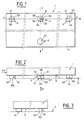
- FIG. 1 is a front view of a flat face equipped with a marking device according to the present invention, said view corresponding to the arrow F1 in FIG. 2.
- FIG. 2 is an elevation view of the flat face of FIG. 1.
- FIG. 3 is a side view of the flat face of FIGS. 1 and 2, according to arrow F3 in FIG. 2.
- FIG. 4 illustrates an application of the device shown in FIGS. 1 to 3.
- a device 1 for example a drilling template (the guide bores of which are not visible), provided with a flat face 2.
- the end facets 3.3, 4.2, 5.1 and 6.2 of elements 3, 4, 5 and 6 are coplanar, so as to determine a reference plane P.
- the edges 3.4, 4.3 and 6.3 of elements 3, 4 and 6 are collinear, so as to determine an axis XX, the elements 4 and 6 being arranged on either side of the element 3.
- the element 5 is at least approximately arranged in alignment with the edge 3.5 of element 3, this edge 3.5 determining an axis YY, perpendicular to the axis XX.
- the reference elements 3 to 5 are arranged in the vicinity of the periphery of the flat face 2.
- FIG. 4 an application of the device illustrated by FIGS. 1 to 3 is shown diagrammatically.
- the device 1 is a drilling template, that is to say a plate pierced with a plurality of guide holes 7 for a drill or a reamer 8.
- the drilling template 1 is fixed to a part 9, in which holes must be drilled in correspondence with the guide holes 7.
- the part 9 is the wing of an aircraft in the vicinity of its root on the structure thereof, the holes to be drilled used for setting places means for fixing said wing on said structure.
- the tool 8 is mounted on the wrist 10 of a robot, not shown, controlled by a computer 11.
- the wrist 10 can be moved in translation, parallel to the three axes Ox, Oy and Oz of a reference trihedron, and can be rotated around two perpendicular axes uu and vv.
- the drilling template 1 occupies a rigorous position relative to the latter. However, because of the possible tolerances of the positioning of the part 9 relative to its support (not shown), the position of the gauge 1 does not coincide, in the system of axes Ox, Oy and Oz of the robot, with the nominal reference position which it should occupy.
- the reference elements 3 to 6 are provided on the flat face 2 of said template 1, described above.
- a distance measuring device 12 for example of the laser type, has been mounted on the wrist 10.
- the distance measuring device 12 emits a signal as soon as it is at a predetermined distance from an obstacle.
- the positioning of the distance device 12, relative to the axis of the tool 8, is fixed and known, so that it is possible to easily deduce the position of the tool 8, when one knows that of detector 12.
- the wrist 10 of the robot is moved, by translation parallel to the plane Ox, Oy, to be brought into line with the position which one of the pads 3 to 6 should occupy , for example the stud 3, if the drilling template 1 occupied a nominal reference position, known to said robot. Since the position tolerances of the drilling template 1 with respect to this nominal reference position are such that the actual position of said stud 3 at least partially covers its nominal position, the detector 12 is therefore plumb of said pad 3. The wrist 10 of the robot is then moved parallel to the axis Oz, in order to approach said pad 3. When the detector 12 is at a predetermined distance from the face 3.3 of the pad 3, it emits a signal towards the calculator 11. The latter therefore knows the exact position of said face 3.3 with respect to the plane Ox, Oy.
- the computer 11 By recommencing similar operations for the other pads 4, 5 and 6, the computer 11 therefore measures the distances separating the faces 4.2, 5.1 and 6.2 respectively of said plane Ox, Oy. He therefore knows the orientation of the plane face 2 with respect to the plane Ox, Oy and he deduces therefrom the value of the angle or angles whose wrist 10 he has to tilt around the axes uu and vv, so that the tool 8 is perpendicular to said flat face 2.
- the wrist 10 is successively moved parallel to the axis Oy to know the distances separating said faces 3.1, 4.1 and 6.1 from the plane Ox, Oz.
- the computer 11 then knows the position of the axis X-X in the reference trihedron Ox, Oy and Oz.
- the pads 3 to 6 therefore allowed, for each hole 7 of the drilling template 1, a change of axes allowing the computer 11 to know precisely the position of said hole and its orientation.
- planar face 2 is material. It could also be immaterial and be determined only by faces of the studs 3, 4, 5 and 6 opposite the faces 3.3, 4.2, 5.1 and 6.2, said studs being secured to an object (not shown) by columns carrying said studs at their free ends. It goes without saying that then the reference mark of this immaterial plane face 2 would make it possible to identify any point of said object which is integral therewith.
Landscapes
- Engineering & Computer Science (AREA)
- Human Computer Interaction (AREA)
- Manufacturing & Machinery (AREA)
- Physics & Mathematics (AREA)
- General Physics & Mathematics (AREA)
- Automation & Control Theory (AREA)
- Length Measuring Devices By Optical Means (AREA)
- Drilling And Boring (AREA)
- Automatic Control Of Machine Tools (AREA)
- Machine Tool Sensing Apparatuses (AREA)
Claims (11)
- Markierungsvorrichtung für eine ebene Fläche (2),
dadurch gekennzeichnet, daß- sie aus drei Markierungselementen besteht (3,4,5), die sich auf besagter ebener Fläche befinden und dergestalt sind, daß:· das erste Markierungselement (3) aus einem rechtwinkligen Trieder besteht, von dem zwei Flächen (3.1,3.2) lotrecht zur besagten ebenen Fläche stehen, während die dritte Fläche (3.3) besagten Trieders parallel zu der besagten ebenen Fläche verläuft, so daß eine Kante (3.6) des besagten Trieders senkrecht zur besagten ebenen Fläche steht und die beiden anderen Kanten (3.4,3.5) des besagten Trieders parallel zur besagten ebenen Fläche verlaufen;· das zweite Markierungselement (4) aus einem rechtwinkligen Dieder besteht, dessen eine Fläche (4.1) senkrecht und dessen andere Fläche (4.2) parallel zur besagten ebenen Fläche steht, so daß die Kante des besagten Dieders (4.3) parallel zur besagten ebenen Fläche verläuft;· das dritte Markierungselement (5) aus einer parallel zur besagten ebenen Fläche stehenden Fläche (5.1) besteht;- und dadurch gekennzeichnet, daß die besagten Markierungselemente (3,4,5) auf der besagten ebenen Fläche so angeordnet sind, daß:· sie nicht auf einer Linie liegen;· diejenigen Flächen (3.3, 4.2 und 5.1) der besagten drei Markierungselemente, die parallel zur besagten ebenen Fläche verlaufen, komplanar sind; und· daß die besagte Kante (4.3) des zweiten Markierungselementes (4) kollinear mit einer (3.1) der beiden parallel zur besagten ebenen Fläche verlaufenden Kanten des ersten Markierungselementes (3) ist. - Vorrichtung nach Anspruch 1,
dadurch gekennzeichnet, daß das besagte dritte Markierungselement (5) so angeordnet ist, daß seine lineare Ausrichtung mit dem besagten ersten Markierungselement (3) zumindest annäherend rechtwinklig zu der durch die kollinearen Kanten (3.1, 4.3) des besagten ersten und zweiten Markierungselementes beschriebenen Richtung erfolgt. - Vorrichtung nach einem der Ansprüche 1 bzw. 2 für den Einsatz bei einer, in durch die besagten kollinearen Kanten des besagten ersten und zweiten Markierungselementes definierter Richtung, verlängerten ebenen Fläche,
dadurch gekennzeichnet, daß sie ein viertes Markierungselement (6) enthält, das aus einem rechtwinkligen Dieder besteht, von dessen Flächen die eine (6.1) senkrecht und die andere (6.2) parallel zur besagten ebenen Fläche verläuft, so daß die Kante (6.3) letzteren Dieders parallel zur besagten ebenen Fläche liegt, daß die parallel zur besagten ebenen Fläche verlaufende Fläche (6.2) des besagten vierten Markierungselementes komplanar mit den entsprechenden Flächen (3.3,4.2,5.1) der besagten drei Markierungselemente ist, sowie dadurch gekennzeichnet, daß die Kante (6.3) des Dieders des besagten vierten Markierungselementes kollinear mit den kollinearen Kanten (3.4,4.3) des besagten ersten und zweiten Markierungselementes ist. - Vorrichtung-nach Anspruch 2 und 3,
dadurch gekennzeichnet, daß das besagte vierte Markierungselement (6) sich auf der, in bezug auf die durch das erste (3) und dritte Markierungselement (5) gebildete Linie, dem besagten zweiten Markierungselement (4) gegenüberliegenden Seite befindet. - Vorrichtung nach einem der Ansprüche 1 bis 4,
dadurch gekennzeichnet, daß die besagten Markierungselemente (3,4,5,6) von zylindrischen Stiften dargestellt werden, deren Endschnittflächen die parallel zur besagten ebenen Fläche liegenden Bezugsflächen bilden, wobei die beiden lotrecht zur besagten ebenen Fläche stehenden Flächen (3.1,3.2) des besagten ersten Markierungselementes (3) radial liegen, während die lotrecht zur besagten ebenen Fläche stehende Fläche (4.1) des besagten zweiten Markierungselements (4) sowie jene (6.1) des eventuellen vierten Markierungselementes (6) diametral liegt. - Vorrichtung nach Anspruch 5 für die Bestimmung der Ausrichtung und Position der besagten ebenen Fläche in bezug auf eine Ausgangsposition,
dadurch gekennzeichnet, daß der Radius der besagten zylindrischen Stifte in allen Richtungen größer ist als die Positionierabweichungen der besagten ebenen Fläche in bezug auf besagte Ausgangsposition. - System, das es gestattet, ein Gerät (8) exakt an eine bestimmte Stelle (7) eines mit einer ebenen Fläche (2) verbundenen Objektes zu führen, wobei die besagte ebene Fläche eine feste, von einer Bezugsausgangsstellung abweichende, aber nur leicht abweichende, Position einnimmt,
dadurch gekennzeichnet, daß:- besagtes Gerät (8) von einer beweglichen Halterung (10) getragen wird, die sich entlang drei senkrecht zueinander stehender Achsen in Translationsverschiebung fortbewegen sowie um zwei rechtwinklig zueinander stehende Achsen drehen kann;- besagte bewegliche Halterung (10) einen Entfernungsmesser (12) trägt;- besagtes System aus drei Markierungselementen (3,4,5) besteht, die sich auf der besagten ebenen Fläche befinden und dergestalt sind, daß:· das erste Markierungselement (3) aus einem rechtwinkligen Trieder besteht, wobei zwei Flächen des besagten Trieders lotrecht zur besagten ebenen Fläche stehen, während die dritte Fläche des besagten Trieders parallel zu der besagten ebenen Fläche verläuft, so daß eine Kante des besagten Trieders senkrecht zur besagten ebenen Fläche steht und die beiden anderen Kanten des besagten Trieders parallel zur besagten ebenen Fläche verlaufen;· das zweite Markierungselement (4) aus einem rechtwinkligen Dieder besteht, dessen eine Fläche senkrecht und dessen andere Fläche parallel zur besagten ebenen Fläche steht, so daß die Kante des besagten Dieders parallel zur besagten ebenen Fläche verläuft;· das dritte Markierungselement (5) aus einer parallel zur besagten ebenen Fläche stehenden Fläche besteht; und- daß die besagten Markierungselemente auf der besagten ebenen Fläche so angeordnet sind, daß:· sie nicht auf einer Linie liegen;· diejenigen Flächen der besagten drei Markierungselemente, die parallel zur besagten ebenen Fläche verlaufen, komplanar sind; und· daß die besagte Kante des zweiten Markierungselementes kollinear mit einer der beiden parallel zur besagten ebenen Fläche verlaufenden Kanten des ersten Markierungselementes ist. - System nach Anspruch 7,
dadurch gekennzeichnet, daß es sich bei dem besagten, mit besagter ebener Fläche (2) verbundenen Objekt um eine Bohrschablone mit einer Vielzahl von Bohrungen (7) handelt, die auf ein zu bearbeitendes Werkstück (9) aufgebracht werden soll, und daß es sich bei dem besagten Gerät (8) um ein Werkzeug handelt, das in zumindest einige der in der besagten Bohrschablone befindlichen Bohrungen eingeführt werden soll. - System nach einem der Ansprüche 7 bzw. 8,
dadurch gekennzeichnet, daß es einen Rechner (11) besitzt, der die Fort- und Schwenkbewegung der besagten beweglichen Halterung (10) in Abhängigkeit von den Meßwerten des besagten Entfernungsmessers (12) steuert. - System nach einem der Ansprüche 7 bis 9,
dadurch gekennzeichnet, daß der besagte Entfernungsmesser (12) ein Signal liefert, sobald er einen vorgegebenen Abstand zu einer Fläche der besagten Markierungselemente erreicht hat. - System nach einem der Ansprüche 7 bis 10,
dadurch gekennzeichnet, daß es sich bei der besagten beweglichen Halterung (10) um das Arbeitsgelenk eines Roboters handelt.
Applications Claiming Priority (2)
| Application Number | Priority Date | Filing Date | Title |
|---|---|---|---|
| FR9013181 | 1990-10-24 | ||
| FR9013181A FR2668408B1 (fr) | 1990-10-24 | 1990-10-24 | Dispositif de repere pour une face plane et systeme d'usinage le mettant en óoeuvre. |
Publications (2)
| Publication Number | Publication Date |
|---|---|
| EP0482983A1 EP0482983A1 (de) | 1992-04-29 |
| EP0482983B1 true EP0482983B1 (de) | 1995-04-19 |
Family
ID=9401531
Family Applications (1)
| Application Number | Title | Priority Date | Filing Date |
|---|---|---|---|
| EP91402780A Expired - Lifetime EP0482983B1 (de) | 1990-10-24 | 1991-10-18 | Lokalisierungsvorrichtung für eine ebene Fläche und diese anwendendes Bearbeitungssystem |
Country Status (4)
| Country | Link |
|---|---|
| US (1) | US5181809A (de) |
| EP (1) | EP0482983B1 (de) |
| DE (1) | DE69109051T2 (de) |
| FR (1) | FR2668408B1 (de) |
Cited By (1)
| Publication number | Priority date | Publication date | Assignee | Title |
|---|---|---|---|---|
| CN106457498A (zh) * | 2014-05-26 | 2017-02-22 | 诺瓦特公司 | 工件运作的方法、系统、计算机程序和计算机程序产品 |
Families Citing this family (25)
| Publication number | Priority date | Publication date | Assignee | Title |
|---|---|---|---|---|
| US5313410A (en) * | 1991-03-28 | 1994-05-17 | Alpha Q, Inc. | Artifact and method for verifying accuracy of a positioning apparatus |
| US5348431A (en) * | 1991-10-09 | 1994-09-20 | Canon Kabushiki Kaisha | Precision cutting process machine and precision cutting process method |
| DE69325910T2 (de) * | 1993-09-28 | 2000-04-20 | Corning Inc. | Feine Bearbeitung einer gekrümmten Halbleiterscheibe |
| DE19681395T1 (de) * | 1995-05-16 | 1998-04-16 | Brown & Sharpe Mfg | Koordinatenmeßmaschine mit Gelenkarm |
| US5616917A (en) * | 1995-05-16 | 1997-04-01 | Brown & Sharpe Manufacturing Company | Device for measuring an angle between pivotally-connected members |
| US6850907B2 (en) * | 1996-12-13 | 2005-02-01 | Cantor Fitzgerald, L.P. | Automated price improvement protocol processor |
| US5905974A (en) * | 1996-12-13 | 1999-05-18 | Cantor Fitzgerald Securities | Automated auction protocol processor |
| US5836068A (en) * | 1997-04-14 | 1998-11-17 | Northrop Grumman Corporation | Mobile gantry tool and method |
| US5848458A (en) * | 1997-05-15 | 1998-12-15 | Northrop Grumman Corporation | Reconfigurable gantry tool |
| US7392214B1 (en) * | 1999-04-30 | 2008-06-24 | Bgc Partners, Inc. | Systems and methods for trading |
| US6276676B1 (en) | 1999-07-30 | 2001-08-21 | Excellon Automation Company | Manual registration pin alignment system |
| US6199290B1 (en) | 1999-07-30 | 2001-03-13 | Excellon Automation Co. | Method and apparatus for automatic loading and registration of PCBs |
| US7392217B2 (en) * | 2001-05-09 | 2008-06-24 | Bgc Partners, Inc. | Systems and methods for controlling traders from manipulating electronic trading markets |
| EP1416363A3 (de) | 2002-10-31 | 2006-07-26 | eSpeed, Inc. | Tastatur für Handelsystem |
| US8566212B2 (en) | 2002-10-31 | 2013-10-22 | Bgc Partners, Inc. | Electronic systems and methods for providing a trading interface with advanced features |
| US8131625B2 (en) * | 2003-11-17 | 2012-03-06 | Bgc Partners, Inc. | Customizable trading display of market data |
| US8131626B2 (en) * | 2003-11-17 | 2012-03-06 | Bgc Partners, Inc. | Customizable trading display of market data |
| US7024787B2 (en) * | 2004-04-01 | 2006-04-11 | United Technologies Corporation | Template for evaluating parts and method of using same |
| US8219480B2 (en) | 2005-03-24 | 2012-07-10 | Bgc Partners, Inc. | Systems and methods for protecting against erroneous price entries in the electronic trading of financial and other instruments |
| US8229832B2 (en) * | 2006-01-09 | 2012-07-24 | Bgc Partners, Inc. | Systems and methods for establishing first on the follow trading priority in electronic trading systems |
| EP3038792A4 (de) | 2013-08-26 | 2017-06-21 | Novator AB | Verfahren, system, computerprogramm und computerprogrammprodukt zur vermessung von objekten |
| US10207333B2 (en) * | 2016-08-14 | 2019-02-19 | The Boeing Company | Tool assembly, system, and method for transferring locations and dimensions of a pattern of holes |
| WO2018080372A1 (en) * | 2016-10-25 | 2018-05-03 | Novator Ab | Method, system, computer program and a computer program product for working of a workpiece |
| ES3049653T3 (en) * | 2017-11-15 | 2025-12-17 | Airbus Operations Slu | Driling template |
| US12358125B2 (en) * | 2022-03-16 | 2025-07-15 | Devon James Perlenfein | Template for forming faucet assembly holes in a countertop |
Family Cites Families (6)
| Publication number | Priority date | Publication date | Assignee | Title |
|---|---|---|---|---|
| GB1334398A (en) * | 1970-07-17 | 1973-10-17 | Werkzeugmasch Heckert Veb | Method of and apparatus for ascertaining fixed value coordi nates or work and measuring spindles |
| DE2210713A1 (de) * | 1972-03-06 | 1973-09-13 | Siemens Ag | Anordnung zur positionierung eines werkzeuges |
| DE2739533C2 (de) * | 1977-09-02 | 1985-09-05 | Dronsek, Max Günter, Dipl.-Ing., 8891 Klingen | Vorrichtung zur Arbeitsspindel-Längeneinstellung an einer numerisch gesteuerten Werkzeugmaschine |
| JPS5940567B2 (ja) * | 1980-06-30 | 1984-10-01 | 安藤電気株式会社 | 異なる穴径を含む複数の穴あけ加工装置 |
| GB2149707B (en) * | 1983-11-15 | 1987-10-28 | Hitachi Shipbuilding Eng Co | Automatic welding apparatus |
| FR2588495B1 (fr) * | 1985-10-16 | 1987-12-11 | Aerospatiale | Ensemble de douille de fixation pour unite d'usinage et unite d'usinage adaptee pour cooperer avec ladite douille |
-
1990
- 1990-10-24 FR FR9013181A patent/FR2668408B1/fr not_active Expired - Lifetime
-
1991
- 1991-10-18 DE DE69109051T patent/DE69109051T2/de not_active Expired - Lifetime
- 1991-10-18 EP EP91402780A patent/EP0482983B1/de not_active Expired - Lifetime
- 1991-10-24 US US07/782,316 patent/US5181809A/en not_active Expired - Lifetime
Cited By (3)
| Publication number | Priority date | Publication date | Assignee | Title |
|---|---|---|---|---|
| CN106457498A (zh) * | 2014-05-26 | 2017-02-22 | 诺瓦特公司 | 工件运作的方法、系统、计算机程序和计算机程序产品 |
| US10150166B2 (en) | 2014-05-26 | 2018-12-11 | Novator Ab | Method, system, computer programme and a computer programme product for working of a work piece |
| CN106457498B (zh) * | 2014-05-26 | 2019-04-23 | 诺瓦特公司 | 工件加工的方法、系统和存储介质 |
Also Published As
| Publication number | Publication date |
|---|---|
| FR2668408B1 (fr) | 1993-01-22 |
| FR2668408A1 (fr) | 1992-04-30 |
| EP0482983A1 (de) | 1992-04-29 |
| DE69109051D1 (de) | 1995-05-24 |
| DE69109051T2 (de) | 1995-11-02 |
| US5181809A (en) | 1993-01-26 |
Similar Documents
| Publication | Publication Date | Title |
|---|---|---|
| EP0482983B1 (de) | Lokalisierungsvorrichtung für eine ebene Fläche und diese anwendendes Bearbeitungssystem | |
| US10514243B2 (en) | Tool for measuring angles and length in structures and frames | |
| GB2151518A (en) | Laser apparatus and method for effectively projecting the axis of rotation of a rotating tool holder | |
| EP0209445A1 (de) | Drehmomentschrauber | |
| EP2798304A1 (de) | Vorrichtung zur messung eines externen oder internen profils eines rohrförmigen bauteils | |
| CH647189A5 (fr) | Dispositif de manipulation d'une piece cylindrique ou spherique. | |
| JP2020193889A (ja) | 位置決め装置、孔検査装置、位置決め方法及び孔検査方法 | |
| EP0163640A1 (de) | Führungswerkzeug | |
| US4211014A (en) | Devices for inspecting bores | |
| FR2542122A1 (fr) | Dispositif de support et d'orientation d'un element optique pour instrument analytique | |
| FR2960521A1 (fr) | Dispositif et procede d'assemblage de supports dans une structure d'aeronef | |
| JP7436672B2 (ja) | ロボット、マスタリング治具、マスタリングシステムおよびマスタリング方法 | |
| US4112581A (en) | Micrometer jig | |
| EP0260583A1 (de) | Taster zur Dimensionsmessung | |
| US6401348B1 (en) | Electrodynamic rotational axis acquisition tool | |
| EP0285555A1 (de) | Spannvorrichtung eines Werkzeughalters auf einer Spannbasis in einem Bearbeitungszentrum, insbesondere zum Drehen | |
| EP0108366B1 (de) | Mess- und Bearbeitungsvorrichtung für die Zahnprothetik | |
| US1463095A (en) | Micrometer attachment | |
| FR2715089A1 (fr) | Centreur pour l'usinage de pièces et applications de ce centreur. | |
| WO2005000128A1 (fr) | Dispositif de positionnement de guide de coupe osseuse | |
| JP2504202Y2 (ja) | Nc旋盤におけるワ―ク寸法測定用治具 | |
| CH683947A5 (fr) | Porte-touche de palpage pour un appareil de mesure. | |
| US2443704A (en) | Tool positioning gauge | |
| EP0034991B1 (de) | Dehnungsmessgerät für Betonproben | |
| EP0330564B1 (de) | System zur Nachprüfung der Programmierung von in der Software einer Werkzeugmaschine enthaltenen Daten |
Legal Events
| Date | Code | Title | Description |
|---|---|---|---|
| PUAI | Public reference made under article 153(3) epc to a published international application that has entered the european phase |
Free format text: ORIGINAL CODE: 0009012 |
|
| AK | Designated contracting states |
Kind code of ref document: A1 Designated state(s): DE GB NL |
|
| 17P | Request for examination filed |
Effective date: 19920518 |
|
| 17Q | First examination report despatched |
Effective date: 19940712 |
|
| GRAA | (expected) grant |
Free format text: ORIGINAL CODE: 0009210 |
|
| AK | Designated contracting states |
Kind code of ref document: B1 Designated state(s): DE GB NL |
|
| GBT | Gb: translation of ep patent filed (gb section 77(6)(a)/1977) |
Effective date: 19950420 |
|
| REF | Corresponds to: |
Ref document number: 69109051 Country of ref document: DE Date of ref document: 19950524 |
|
| NLT2 | Nl: modifications (of names), taken from the european patent patent bulletin |
Owner name: AEROSPATIALE SOCIETE NATIONALE INDUSTRIELLE |
|
| PLBE | No opposition filed within time limit |
Free format text: ORIGINAL CODE: 0009261 |
|
| STAA | Information on the status of an ep patent application or granted ep patent |
Free format text: STATUS: NO OPPOSITION FILED WITHIN TIME LIMIT |
|
| 26N | No opposition filed | ||
| REG | Reference to a national code |
Ref country code: GB Ref legal event code: IF02 |
|
| PGFP | Annual fee paid to national office [announced via postgrant information from national office to epo] |
Ref country code: DE Payment date: 20091026 Year of fee payment: 19 |
|
| PGFP | Annual fee paid to national office [announced via postgrant information from national office to epo] |
Ref country code: GB Payment date: 20091022 Year of fee payment: 19 |
|
| PGFP | Annual fee paid to national office [announced via postgrant information from national office to epo] |
Ref country code: NL Payment date: 20101013 Year of fee payment: 20 |
|
| GBPC | Gb: european patent ceased through non-payment of renewal fee |
Effective date: 20101018 |
|
| PG25 | Lapsed in a contracting state [announced via postgrant information from national office to epo] |
Ref country code: GB Free format text: LAPSE BECAUSE OF NON-PAYMENT OF DUE FEES Effective date: 20101018 |
|
| REG | Reference to a national code |
Ref country code: DE Ref legal event code: R119 Ref document number: 69109051 Country of ref document: DE Effective date: 20110502 |
|
| REG | Reference to a national code |
Ref country code: NL Ref legal event code: V4 Effective date: 20111018 |
|
| PG25 | Lapsed in a contracting state [announced via postgrant information from national office to epo] |
Ref country code: NL Free format text: LAPSE BECAUSE OF EXPIRATION OF PROTECTION Effective date: 20111018 |
|
| PG25 | Lapsed in a contracting state [announced via postgrant information from national office to epo] |
Ref country code: DE Free format text: LAPSE BECAUSE OF NON-PAYMENT OF DUE FEES Effective date: 20110502 |