EP0483119A2 - Construction de filtre - Google Patents
Construction de filtre Download PDFInfo
- Publication number
- EP0483119A2 EP0483119A2 EP92200200A EP92200200A EP0483119A2 EP 0483119 A2 EP0483119 A2 EP 0483119A2 EP 92200200 A EP92200200 A EP 92200200A EP 92200200 A EP92200200 A EP 92200200A EP 0483119 A2 EP0483119 A2 EP 0483119A2
- Authority
- EP
- European Patent Office
- Prior art keywords
- filter medium
- support
- cartridge
- assembly according
- filter
- Prior art date
- Legal status (The legal status is an assumption and is not a legal conclusion. Google has not performed a legal analysis and makes no representation as to the accuracy of the status listed.)
- Withdrawn
Links
- 239000000853 adhesive Substances 0.000 claims abstract description 10
- 230000001070 adhesive effect Effects 0.000 claims abstract description 10
- 239000012530 fluid Substances 0.000 claims abstract description 10
- 238000007789 sealing Methods 0.000 claims description 8
- 239000000446 fuel Substances 0.000 claims description 6
- 239000000463 material Substances 0.000 claims description 6
- XLYOFNOQVPJJNP-UHFFFAOYSA-N water Substances O XLYOFNOQVPJJNP-UHFFFAOYSA-N 0.000 claims description 4
- 230000003068 static effect Effects 0.000 claims description 2
- 238000004519 manufacturing process Methods 0.000 claims 1
- 210000003739 neck Anatomy 0.000 claims 1
- 229910052755 nonmetal Inorganic materials 0.000 claims 1
- 150000002843 nonmetals Chemical class 0.000 claims 1
- 230000013011 mating Effects 0.000 description 6
- 239000007788 liquid Substances 0.000 description 3
- WZQNNALXEJBHLB-UHFFFAOYSA-N O.OOO Chemical compound O.OOO WZQNNALXEJBHLB-UHFFFAOYSA-N 0.000 description 2
- 239000002828 fuel tank Substances 0.000 description 2
- 239000002184 metal Substances 0.000 description 2
- SYJPAKDNFZLSMV-HYXAFXHYSA-N (Z)-2-methylpropanal oxime Chemical compound CC(C)\C=N/O SYJPAKDNFZLSMV-HYXAFXHYSA-N 0.000 description 1
- 229910000619 316 stainless steel Inorganic materials 0.000 description 1
- 229920000742 Cotton Polymers 0.000 description 1
- 230000000712 assembly Effects 0.000 description 1
- 238000000429 assembly Methods 0.000 description 1
- 238000004581 coalescence Methods 0.000 description 1
- 230000001419 dependent effect Effects 0.000 description 1
- 239000004744 fabric Substances 0.000 description 1
- 238000001914 filtration Methods 0.000 description 1
- 239000011521 glass Substances 0.000 description 1
- 239000003365 glass fiber Substances 0.000 description 1
- 239000012535 impurity Substances 0.000 description 1
- 239000007769 metal material Substances 0.000 description 1
- 239000002245 particle Substances 0.000 description 1
- 230000003014 reinforcing effect Effects 0.000 description 1
- 230000000717 retained effect Effects 0.000 description 1
- 239000007787 solid Substances 0.000 description 1
- 239000000126 substance Substances 0.000 description 1
Images


Classifications
-
- B—PERFORMING OPERATIONS; TRANSPORTING
- B01—PHYSICAL OR CHEMICAL PROCESSES OR APPARATUS IN GENERAL
- B01D—SEPARATION
- B01D29/00—Filters with filtering elements stationary during filtration, e.g. pressure or suction filters, not covered by groups B01D24/00 - B01D27/00; Filtering elements therefor
- B01D29/11—Filters with filtering elements stationary during filtration, e.g. pressure or suction filters, not covered by groups B01D24/00 - B01D27/00; Filtering elements therefor with bag, cage, hose, tube, sleeve or like filtering elements
- B01D29/13—Supported filter elements
- B01D29/15—Supported filter elements arranged for inward flow filtration
-
- B—PERFORMING OPERATIONS; TRANSPORTING
- B01—PHYSICAL OR CHEMICAL PROCESSES OR APPARATUS IN GENERAL
- B01D—SEPARATION
- B01D29/00—Filters with filtering elements stationary during filtration, e.g. pressure or suction filters, not covered by groups B01D24/00 - B01D27/00; Filtering elements therefor
- B01D29/96—Filters with filtering elements stationary during filtration, e.g. pressure or suction filters, not covered by groups B01D24/00 - B01D27/00; Filtering elements therefor in which the filtering elements are moved between filtering operations; Particular measures for removing or replacing the filtering elements; Transport systems for filters
-
- B—PERFORMING OPERATIONS; TRANSPORTING
- B01—PHYSICAL OR CHEMICAL PROCESSES OR APPARATUS IN GENERAL
- B01D—SEPARATION
- B01D2201/00—Details relating to filtering apparatus
- B01D2201/04—Supports for the filtering elements
- B01D2201/0415—Details of supporting structures
-
- B—PERFORMING OPERATIONS; TRANSPORTING
- B01—PHYSICAL OR CHEMICAL PROCESSES OR APPARATUS IN GENERAL
- B01D—SEPARATION
- B01D2201/00—Details relating to filtering apparatus
- B01D2201/40—Special measures for connecting different parts of the filter
- B01D2201/4015—Bayonet connecting means
-
- B—PERFORMING OPERATIONS; TRANSPORTING
- B01—PHYSICAL OR CHEMICAL PROCESSES OR APPARATUS IN GENERAL
- B01D—SEPARATION
- B01D2201/00—Details relating to filtering apparatus
- B01D2201/40—Special measures for connecting different parts of the filter
- B01D2201/4084—Snap or Seeger ring connecting means
-
- Y—GENERAL TAGGING OF NEW TECHNOLOGICAL DEVELOPMENTS; GENERAL TAGGING OF CROSS-SECTIONAL TECHNOLOGIES SPANNING OVER SEVERAL SECTIONS OF THE IPC; TECHNICAL SUBJECTS COVERED BY FORMER USPC CROSS-REFERENCE ART COLLECTIONS [XRACs] AND DIGESTS
- Y10—TECHNICAL SUBJECTS COVERED BY FORMER USPC
- Y10S—TECHNICAL SUBJECTS COVERED BY FORMER USPC CROSS-REFERENCE ART COLLECTIONS [XRACs] AND DIGESTS
- Y10S210/00—Liquid purification or separation
- Y10S210/05—Coalescer
-
- Y—GENERAL TAGGING OF NEW TECHNOLOGICAL DEVELOPMENTS; GENERAL TAGGING OF CROSS-SECTIONAL TECHNOLOGIES SPANNING OVER SEVERAL SECTIONS OF THE IPC; TECHNICAL SUBJECTS COVERED BY FORMER USPC CROSS-REFERENCE ART COLLECTIONS [XRACs] AND DIGESTS
- Y10—TECHNICAL SUBJECTS COVERED BY FORMER USPC
- Y10S—TECHNICAL SUBJECTS COVERED BY FORMER USPC CROSS-REFERENCE ART COLLECTIONS [XRACs] AND DIGESTS
- Y10S210/00—Liquid purification or separation
- Y10S210/17—Twist-on
Definitions
- the invention relates to filter assemblies, e.g., those used to filter aviation fuel.
- Filters used to remove impurities from aviation fuel and to cause water in the fuel to coalesce into large drops that can settle and be removed by a sump pump are often sealably mounted over inlet openings in the bottom or side walls of fuel tanks or pressurized vessels through which the fuel flows immediately prior to discharge, such that liquid must pass through the filter before it enters the tank or vessel.
- These filters are often cylindrical and have an axial opening at the bottom and a tubular filter medium wall through which there is so-called inside-out flow. Similarly shaped filters can be mounted over outlets, in which case there would be outside-in flow.
- These cylindrical filters have typically been secured by mating a threaded lower end of a filter cartridge base with a threaded opening in the floor of the tank or vessel or by sliding the filter over a floor-mounted threaded rod and holding it in place with a nut at the top of the filter. If the filters are overtightened, the threads may become worn, and the filters hard to remove. If the filters are undertightened, the filter may not seal well and may even be loosened by vibrations.
- the invention features in general a filter assembly comprising a base for supporting and providing fluid connection to a removable filter cartridge, the base having a hollow connecting end for mating with the cartridge, a removable filter cartridge comprising a filter medium and having a connecting end shaped to mate coaxially with the end of the base in a rotatable, telescopic relationship, the connecting end of one of the base and the cartridge having lug means extending radially toward the end of the other, the other connecting end having corresponding passage means for lockably receiving the lug means, the telescopically related mating ends of the base and cartridge providing radially opposed surfaces of circular cross-section about the mutual axis of the connecting ends of the base and cartridge, and a circular elastomeric sealing ring providing a radial seal between the circular cross-section surfaces, preventing liquid flow past it between the telescopic ends.
- one connecting end has an annular groove, and the ring is mounted in this groove; the groove is in the cylindrical surface of the filter cartridge; the cartridge is constructed from non-metallic material; the cartridge is completely made of material that can be incinerated; the cartridge includes static dissipative material; the filter medium includes a pleated filter on the inside of the support and layers on the outside of the support; the filter cartridge has a handle at its top permitting rotation and connection or removal of the cartridge; and the handle is rotatable between an upright position and a horizontal position.
- the invention features in general a filter assembly comprising a base for supporting and providing fluid connection to a removable filter cartridge, the base having a hollow connecting end for mating with the cartridge, a removable filter cartridge comprising a filter medium and having a connecting end shaped to mate coaxially with the end of the base in a rotatable, telescopic relationship, the connecting end of one of the base and the cartridge being provided with lug means extending radially toward the end of the other, the other of the connecting ends having corresponding passage means for lockably receiving the lug means, the passage means extending along a circumferential path to an angular position and in an axial direction from the circumferential path at the angular position to a locked position in which the lug means is prevented from circumferential movement, and a locking mechanism biasing the lugs in the axial direction into the locked position, whereby the cartridge can be easily secured to the base and removed from the base, and unintended disconnection of the cartridge from the base owing to vibration is avoided.
- lug means extend from the cartridge, and the passage means are located in the base; the base is provided with struts tranversing the fluid passage; and the locking mechanism is a spring (most preferably a wave spring).
- the invention features in general a filter cartridge assembly comprising a filter medium having a circular cross section end, a filter medium support having a circular cross section end and supporting said filter medium, a connecting end member having a fluid flow passage therethrough; said assembly being characterised in further comprising: means for mechanically locking said support to said connecting end member; and in that said connecting end member has an annular channel surrounding said passage, said circular cross section ends of said filter medium and said filter medium support being received in said channel; and in that adhesive in said annular channel secures said end member, said filter medium support and said filter medium and sealably secures said filter medium support to said end member.
- the means for mechanically locking comprises wedge means applied to the connecting end member, and corresponding slot means on the support to receive the wedge means;
- the connecting member and the support are constructed from structural plastic;
- the slots are provided on a flat ring having a flow passage therethrough;
- the filter assembly further comprises a second filter medium and support mechanically and adhesively connected through a sealing member with annular channels to the first support.
- the invention provides a filter cartridge which is quickly and easily connected to a permanently mounted base in a tank or vessel. Vibrations will not cause the filter to lose fluid tight contact with the base. Further, the invention features a filter cartridge which is more readily constructed than prior filters, and can be advantageously disposed of by incineration after usage, as there are no metal parts.
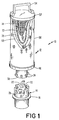
- Fig. 1 is a diagrammatic perspective view, partially broken away, of a filter base and a mating removable filter cartridge according to the invention.
- Fig. 2 is a partial elevation, partly broken away, showing the Fig. 1 base and cartridge lockably connected together.
- Fig. 3 is a plan view of the Fig. 1 base.
- Fig. 4 is an exploded perspective view of a connecting end member and filter medium support of the Fig. 1 cartridge.
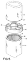
- Fig. 5 is an exploded perspective view of a portion of an alternative embodiment of the Fig. 1 cartridge.
- filter assembly 10 includes removable filter cartridge 12 and plastic adapter base 14 mounted on metal stool 16, welded to fuel tank wall 18, so that fluid entering or leaving the tank must pass through stool 16 and base 14.
- Base 14 has a series of locking passages 22 for mating with lugs 24 on filter cartridge 12.
- Each passage 22 extends along an entrance 26 to a horizontal circumferential path ending at an angular position, and then extends axially upward slightly to a locked position circumferentially adjacent to locking tab 28, which prevents rotational movement of lug 24 within passage 22 when lug 24 is urged upward into the locked position.
- Base 14 has a cylindrical surface 30 defining a fluid passage and is provided with struts 32, shown in Fig. 3, which extend radially from hub 34 to surface 30.
- Lip 37 directly on top of struts 32, supports wave spring 36 against which filter cartridge 12 is applied.
- Wave spring 36 is made of 0.030"(0.0762 cm)thick, 1/8" (0.3175cm) wide, 316 stainless steel, making about 3 complete coils and bent to provide 3 1/2 peaks per 360 o .
- the free height of spring 36 is 3/4" (1.905cm), and it takes between 25 and 35 lb. force (111.2 to 155.7 N) to push spring 36 down to its 1/4" (0.635 cm) compressed height.
- Cartridge 12 includes lower cylindrical surface 38, telescopically received in and facing surface 30 of base 14.
- Surface 38 includes annular recess 40 in which elastomeric sealing O-ring 42 is retained.
- O-ring 42 serves to tightly seal cartridge 12 and base 14 together, regardless of application of any axial force,as with gaskets.
- surface 30 is 3.000" + O.OO2"-O.OOO" (7.620 + O.OO5O8-O.OOO cm) in diameter; surface 38 is 2.997" + .OOO" - .OO1" (7.61238 + O.OOO - O.OO254 cm) in diameter; groove 40 is 2.778" + .OOO" - .OO2" (7.05612 + O.OOO - O.OO508 cm) in diameter and O.19O" + .OO2 - .OO3 (O.4826 + O.OO5O8 - O.OO762cm) wide, and O-ring 42 (industry designation 2-232) has a 2.734" (6.94436 cm) inner diameter and a O.139" + .OO4 - .OO4" (O.353O6 + O.O1O16 - O.O1O16 cm) cross section.
- Base 14 is connected to the stool 16 of base 12 by bolt 44.
- filter cartridge 12 includes connecting end member 46 with annular channel 48 into which the lower end of tubular filter medium 50 is sealably connected.
- the other end of filter medium 50 is similarly connected in a channel (not shown) in cap 52, provided with a pivotally mounted handle 54.
- Medium 50 includes a series of layers supported by plastic framed support 56. These include outer cotton fabric sock 65, 2" (5.08cm) helical overlapping wrap of plastic screen 68,1/4" (0.635 cm) thick layer 70 of glass fibre thereunder, sheet of plastic screen 72 thereunder wrapped around ribs and columns of framed support 56, and pleated filter medium 74 on the inside of support 56.
- Pleated filter medium 74 is approximately 7/8" (2.2225cm) in overall radial dimension, the inner portion at the bottom fitting within annular channel 48.
- connecting end member 46 is provided with three axial pins 58 with oversized heads 60.
- Oversized heads 60 are designed to fit into slots 62 of lower flat ring 63.
- Slots 62 consist of circular openings 66, larger in diameter than the heads 60 of pins 58, and elongated portions 64, narrower than heads 60 of pins 58.
- pins 58 are in narrow elongated portions 64, mechanically locking support 56 to end member 46 by wedging ring 63 against radial ribs 80.
- connecting end member 46 and frame 56 are made of structural plastic (available under the trade designation Valox from G.E., 15% glass filled).
- Filter cartridge 12 is manufactured by inserting the lower end of filter components 65, 68, 70, 72, 74 and support 56 into annular groove 48 (already containing exothermic adhesive), mechanically locking support 56 to end member 46 using pins 58 and slots 64, and letting the adhesive set.
- the position of heads 60, the thickness of ring 63 and the height of radial ribs 80 are such that rotation of support 50 is against frictional forces acting to wedge support 56 in place.
- the other end of the filter cartridge is connected to top cap 52, shown in Fig. 1.
- both mechanical locking and chemical support are used to connect members together, more securely than prior use of adhesive alone.
- Filter cartridge 12 can be readily inserted into a fixed adapter base 14 by positioning the cartridge over the base as shown in Fig. 1. Lugs 24 of the cartridge are inserted into passages 22 of the base and pushed down using handle 54. The cartridge is then pushed against wavespring 36, rotated to the end of the circumferential portion of the passage, and released, wavespring 36 urging lugs 24 into locked positioned next to tabs 28. In this way filter cartridge 14 is securely fixed to base 12 and cannot be loosened by mere vibrational forces. The forces resulting from pressure difference inside and outside of cartridge 12 act upward, the same direction as the spring, reinforcing the locking.
- sealing O-ring 42 prevents liquid flow around the bottom of connecting end 46.
- the seal provided by O-ring 42 advantageously is not dependent on axial forces, as flat gaskets are.
- Filter medium 50 prevents solid particles from entering the tank and also cause coalescence of water within the fuel entering the tank, so that, upon leaving the filter, the water is in the form of large droplets that settle to the bottom of the tank, where they are removed by a sump pump or other means.
- Removal of the cartridge is accomplished by pushing down on cartridge 12, using handle 54, and rotating the assembly such that lugs 24 are moved to entrances 26.
- the cartridge can then be pulled from the base, and then quickly be replaced by a second cartridge inserted into base 14, the entire changeover taking a matter of seconds, which is particularly significant when replacing a large number of filter cartridges at one time. Since the entire cartridge is constructed of combustible material, the removed cartridge can be incinerated and readily disposed of.
- FIG. 5 further filter medium 80 is shown prior to connection sealing member 82, including two annular channels 84 with locking pins 86 for connection to slots 88 on framed support 56 of lower medium 50 and framed support 90 of further medium 80.
- a cap 52 and handle 54 (not shown) are attached to the top of support 90 and medium 80.
- the overall cartridge thus has twice the filtering and coalescing capacity of single stage filter cartridge 12.
Landscapes
- Chemical & Material Sciences (AREA)
- Chemical Kinetics & Catalysis (AREA)
- Filtration Of Liquid (AREA)
- Filtering Of Dispersed Particles In Gases (AREA)
Applications Claiming Priority (2)
| Application Number | Priority Date | Filing Date | Title |
|---|---|---|---|
| US870237 | 1978-01-17 | ||
| US06/870,237 US4871455A (en) | 1986-06-03 | 1986-06-03 | Filter assembly with lockable lug means |
Related Parent Applications (2)
| Application Number | Title | Priority Date | Filing Date |
|---|---|---|---|
| EP87304941A Division EP0249395A3 (fr) | 1986-06-03 | 1987-06-03 | Appareil de Filtrage |
| EP87304941.5 Division | 1987-06-03 |
Publications (2)
| Publication Number | Publication Date |
|---|---|
| EP0483119A2 true EP0483119A2 (fr) | 1992-04-29 |
| EP0483119A3 EP0483119A3 (en) | 1992-06-03 |
Family
ID=25355009
Family Applications (2)
| Application Number | Title | Priority Date | Filing Date |
|---|---|---|---|
| EP87304941A Withdrawn EP0249395A3 (fr) | 1986-06-03 | 1987-06-03 | Appareil de Filtrage |
| EP19920200200 Withdrawn EP0483119A3 (en) | 1986-06-03 | 1987-06-03 | Filter assembly |
Family Applications Before (1)
| Application Number | Title | Priority Date | Filing Date |
|---|---|---|---|
| EP87304941A Withdrawn EP0249395A3 (fr) | 1986-06-03 | 1987-06-03 | Appareil de Filtrage |
Country Status (4)
| Country | Link |
|---|---|
| US (1) | US4871455A (fr) |
| EP (2) | EP0249395A3 (fr) |
| JP (1) | JPS6365918A (fr) |
| AU (1) | AU600273B2 (fr) |
Cited By (8)
| Publication number | Priority date | Publication date | Assignee | Title |
|---|---|---|---|---|
| WO1995007745A1 (fr) * | 1993-09-15 | 1995-03-23 | Parker Hannifin Corporation | Filtre a carburant |
| US5855780A (en) * | 1996-11-04 | 1999-01-05 | Advanced Performance Technology, Inc. | Fuel filter element with flow actuator |
| US6053334A (en) * | 1993-09-15 | 2000-04-25 | Parker Hannifin Customer Support Inc. | Fuel filter with valve device |
| US6113781A (en) * | 1993-09-15 | 2000-09-05 | Parker-Hannifin Corporation | Fuel filter with dual flow |
| US7335300B1 (en) | 2004-07-14 | 2008-02-26 | Wix Filtration Corp Llc | Fluid filter element |
| WO2012017055A1 (fr) * | 2010-08-06 | 2012-02-09 | Beko Technologies Gmbh | Séparateur d'huile en cartouche |
| WO2015086376A1 (fr) * | 2013-12-11 | 2015-06-18 | Mann+Hummel Gmbh | Boîtier de filtre, filtre à fluide ainsi que procédé de montage du couvercle du boîtier de filtre sur un raccord fileté du filtre à fluide |
| US10525388B2 (en) | 2014-08-05 | 2020-01-07 | Spx Flow Technology Usa, Inc. | Multi-cartridge filter adapter and interface system and method |
Families Citing this family (66)
| Publication number | Priority date | Publication date | Assignee | Title |
|---|---|---|---|---|
| US5045192A (en) * | 1986-06-03 | 1991-09-03 | Facet Enterprises, Inc. | Filter assembly with lockable lug means |
| US5000847A (en) * | 1989-09-01 | 1991-03-19 | Huang Andrew B | Oil filter construction for hand spinning |
| US5035797A (en) * | 1990-02-14 | 1991-07-30 | Stanadyne Automotive Corp. | Key system for filter assembly |
| US5141637A (en) * | 1990-11-30 | 1992-08-25 | Pall Corporation | Filter units with end connectors |
| DE4039192C1 (fr) * | 1990-12-08 | 1992-07-30 | Hydac Filtertechnik Gmbh, 6603 Sulzbach, De | |
| AU648418B2 (en) * | 1991-07-01 | 1994-04-21 | Kelray Australia Pty. Ltd. | Fuel filter assembly |
| AU656513B3 (en) * | 1991-07-01 | 1995-02-02 | Kelray Australia Pty. Ltd. | Fuel filter assembly |
| US5435915A (en) * | 1992-04-10 | 1995-07-25 | Pall Corporation | Connector for sealing stacked filter elements |
| US5443724A (en) * | 1992-12-23 | 1995-08-22 | Pall Corporation | Apparatus for separating the components of a liquid/liquid mixture |
| US5611922A (en) * | 1993-08-16 | 1997-03-18 | Donaldson Company | Filter cartridge retention system |
| US5725621A (en) * | 1995-07-07 | 1998-03-10 | Flair Corporation | Filter end cap attachment |
| US5876599A (en) * | 1997-04-07 | 1999-03-02 | Kuss Corporation | Compact in-tank fuel filter and module |
| DE19744574B4 (de) * | 1997-10-09 | 2005-12-22 | Schenk-Filterbau Gmbh | Filtermodul |
| US5954846A (en) * | 1997-10-23 | 1999-09-21 | Alfa Laval Agri Inc. | Efficient, replaceable air filter system for milking machine pulsators |
| GB2333247A (en) * | 1998-01-17 | 1999-07-21 | Lucas Ind Plc | Lock mechanism for a filter housing |
| ES2192058T3 (es) * | 1998-07-25 | 2003-09-16 | Mueller Drm Ag | Dispositivo de fijacion de elementos de filtro de bujia que se suspenden de un tubo colector en un recipiente a presion. |
| US6129837A (en) * | 1998-11-06 | 2000-10-10 | Nurse, Jr.; Harry L. | Waste water treatment filter including a waste water level control alert device |
| US6217762B1 (en) | 1999-03-29 | 2001-04-17 | Jeffrey G. Rooney | Specially adapted oil filter casing |
| US6217763B1 (en) * | 1999-08-11 | 2001-04-17 | Usf Filtration And Separation Group, Inc. | Back-flushable filter cartridge assemblies |
| US6422396B1 (en) | 1999-09-16 | 2002-07-23 | Kaydon Custom Filtration Corporation | Coalescer for hydrocarbons containing surfactant |
| ES2195946T3 (es) * | 1999-12-03 | 2003-12-16 | Parker Hannifin Corp | Valvula con pestillo de enganche para filtro de carburante. |
| DE60117260T2 (de) | 2000-05-12 | 2006-10-05 | Pall Corp. | Filtrationssysteme |
| ATE446800T1 (de) | 2000-05-12 | 2009-11-15 | Pall Corp | Filter |
| US6328883B1 (en) | 2000-05-31 | 2001-12-11 | Parker-Hannifin Corporation | Fuel filter assembly with priming pump |
| US6387142B1 (en) * | 2000-06-19 | 2002-05-14 | Chicopee Engineering Associates, Inc. | Air/oil separator cap attachment system |
| US7168573B2 (en) * | 2002-06-07 | 2007-01-30 | Baldwin Filters, Inc. | Environmentally friendly filter cartridge |
| US6857399B2 (en) * | 2002-08-12 | 2005-02-22 | Tecumseh Products Company | Air cleaner assembly for internal combustion engines |
| US6833070B2 (en) * | 2003-01-06 | 2004-12-21 | Delphi Technologies, Inc. | Fuel strainer assembly |
| US20060191839A1 (en) * | 2003-01-20 | 2006-08-31 | Howard James A | High capacity filter element |
| US7395936B2 (en) * | 2003-02-26 | 2008-07-08 | Parker-Hannifin Corporation | Filter element with vent orifice and assembly therefore |
| US20040195171A1 (en) * | 2003-04-04 | 2004-10-07 | Frye Randy Charles | Reversible element guide |
| US9233323B1 (en) | 2004-02-17 | 2016-01-12 | Peter W. Gavin | T-housing for septic tank |
| DE102004042726A1 (de) * | 2004-09-03 | 2006-03-09 | B + V Industrietechnik Gmbh | Vorrichtung zum Abscheiden von Beimengungen aus Flüssigkeiten |
| KR101276509B1 (ko) * | 2005-07-20 | 2013-06-18 | 쓰리엠 이노베이티브 프로퍼티즈 컴파니 | 유체 여과 시스템 |
| US8293103B2 (en) | 2005-12-08 | 2012-10-23 | Donaldson Company, Inc. | Spin-on filter assembly and methods |
| US7520925B2 (en) * | 2005-12-21 | 2009-04-21 | Sure Seal, Inc. | Filter and silencer with a quick disconnect lid |
| US8066790B2 (en) * | 2007-03-16 | 2011-11-29 | 3M Innovative Properties Company | Fluid filter cartridge and housing |
| US8709248B2 (en) * | 2007-07-11 | 2014-04-29 | Baldwin Filters, Inc. | Molded filter end cap and method of manufacture |
| CN102149439B (zh) * | 2008-09-16 | 2014-03-12 | 3M创新有限公司 | 滤筒和利用线性致动的系统 |
| US8893689B2 (en) | 2010-01-27 | 2014-11-25 | Cummins Filtration Ip, Inc. | Crankcase ventilation self-cleaning coalescer with intermittent rotation |
| US8940068B2 (en) | 2010-01-27 | 2015-01-27 | Cummins Filtration Ip Inc. | Magnetically driven rotating separator |
| US8794222B2 (en) | 2010-01-27 | 2014-08-05 | Cummins Filtration Ip, Inc. | Crankcase ventilation inside-out flow rotating coalescer |
| US9194265B2 (en) | 2010-01-27 | 2015-11-24 | Cummins Filtration Ip, Inc. | Rotating separator with housing preventing separated liquid carryover |
| US8974567B2 (en) * | 2010-01-27 | 2015-03-10 | Cummins Filtration Ip Inc. | Rotating coalescer with keyed drive |
| GB2477942B (en) | 2010-02-18 | 2012-07-04 | Icon Technology Systems Ltd | Water filters |
| DE102010020727B4 (de) * | 2010-05-17 | 2012-01-12 | Mann + Hummel Gmbh | Filter, Filterelement, Befestigungsgehäuseteil eines Filtergehäuses und Teleskopschaltelement einer Schalteinrichtung einer lösbaren Rastverbindung |
| DE102010043836A1 (de) * | 2010-11-04 | 2012-05-10 | Hengst Gmbh & Co. Kg | Filter mit einem austauschbaren Filtereinsatz |
| US10150071B2 (en) | 2011-04-18 | 2018-12-11 | Bulk Tank, Inc. | Filter guide ring |
| US8657898B2 (en) | 2011-09-22 | 2014-02-25 | Bulk Tank, Inc. | Air filter spin flow inlet/outlet housing |
| DE102011081141A1 (de) * | 2011-08-17 | 2013-02-21 | Robert Bosch Gmbh | Filtereinrichtung mit einem Filtergehäuse und einem Entwässerer |
| IN2014CN03311A (fr) | 2011-11-04 | 2015-07-03 | Cummins Filtration Ip Inc | |
| EP3449722B1 (fr) * | 2012-08-01 | 2021-09-29 | Pioneer Pet Products, LLC | Filtre pour pompe submersible |
| EP3142768B1 (fr) * | 2014-05-15 | 2018-04-18 | UFI Filters S.p.A. | Groupe filtre |
| JP6484064B2 (ja) * | 2015-02-25 | 2019-03-13 | ヤマシンフィルタ株式会社 | フィルタエレメント |
| USD761934S1 (en) * | 2015-05-19 | 2016-07-19 | 3M Innovative Properties Company | Filter cartridge |
| USD761383S1 (en) * | 2015-05-19 | 2016-07-12 | Electrolux Home Products, Inc. | Filter cartridge |
| USD761382S1 (en) * | 2015-05-19 | 2016-07-12 | Electrolux Home Products, Inc. | Filter cartridge |
| USD762812S1 (en) * | 2015-05-19 | 2016-08-02 | 3M Innovative Properties Company | Filter cartridge |
| US10052576B2 (en) | 2015-07-27 | 2018-08-21 | Pall Corporation | Filter assembly |
| US9598919B1 (en) | 2015-09-30 | 2017-03-21 | Reme, L.L.C. | Modified filter screen |
| JP6585789B2 (ja) * | 2018-08-31 | 2019-10-02 | ヤマシンフィルタ株式会社 | フィルタエレメント |
| USD913416S1 (en) | 2018-11-20 | 2021-03-16 | Ningbo Pureza Technology, LLC | Water filter cartridge |
| USD894329S1 (en) | 2018-11-20 | 2020-08-25 | Ningbo Pureza Technology, LLC | Water filter cartridge |
| USD911487S1 (en) | 2018-11-20 | 2021-02-23 | Ningbo Pureza Technology, LLC | Water filter cartridge |
| USD907176S1 (en) | 2018-11-20 | 2021-01-05 | Ningbo Pureza Technology, LLC | Water filter cartridge |
| US20250001333A1 (en) * | 2023-06-30 | 2025-01-02 | Caterpillar Inc. | Filter, filter component, and filter connector system having interlocking tabs and retention elements |
Family Cites Families (15)
| Publication number | Priority date | Publication date | Assignee | Title |
|---|---|---|---|---|
| BE554104A (fr) * | ||||
| US2751084A (en) * | 1954-03-11 | 1956-06-19 | Purolator Products Inc | Fuel tank filter installation |
| US3160000A (en) * | 1961-10-19 | 1964-12-08 | Gerald W Mosher | Sediment testing device |
| US3272340A (en) * | 1963-05-22 | 1966-09-13 | Hungerford & Terry Inc | Quickly detachable strainer system for water treatment tanks |
| DE1198790B (de) * | 1963-08-19 | 1965-08-19 | Putsch & Co H | Kerzenfilter |
| CH434574A (fr) * | 1966-02-25 | 1967-04-30 | Domnick Hunter Eng | Filtre |
| DE1761353A1 (de) * | 1968-05-08 | 1971-05-19 | Hansa Metallwerke Ag | Filtertrockner,insbesondere fuer Kaelteanlagen |
| US3458050A (en) * | 1968-09-10 | 1969-07-29 | Pall Corp | Frustoconical filter fittings |
| US3490594A (en) * | 1968-11-21 | 1970-01-20 | Fram Corp | Filter |
| US4052307A (en) * | 1976-07-08 | 1977-10-04 | Wix Corporation | Universal filter mounting attachment |
| US4210537A (en) * | 1978-09-18 | 1980-07-01 | Ecodyne Corporation | Liquid treatment apparatus |
| US4320005A (en) * | 1979-03-21 | 1982-03-16 | Degraffenreid Howard T | Coalescer or filter end cap |
| JPS6029287B2 (ja) * | 1981-07-29 | 1985-07-10 | 栄市 杉浦 | 液体濾過機 |
| US4559138A (en) * | 1983-10-03 | 1985-12-17 | Harmsco, Inc. | End connected filter cartridges |
| DE3407433A1 (de) * | 1984-02-29 | 1985-08-29 | Kraftwerk Union AG, 4330 Mülheim | Filterkerze |
-
1986
- 1986-06-03 US US06/870,237 patent/US4871455A/en not_active Expired - Fee Related
-
1987
- 1987-06-02 AU AU73739/87A patent/AU600273B2/en not_active Ceased
- 1987-06-03 EP EP87304941A patent/EP0249395A3/fr not_active Withdrawn
- 1987-06-03 EP EP19920200200 patent/EP0483119A3/en not_active Withdrawn
- 1987-06-03 JP JP62139643A patent/JPS6365918A/ja active Granted
Cited By (15)
| Publication number | Priority date | Publication date | Assignee | Title |
|---|---|---|---|---|
| US6171491B1 (en) | 1993-09-15 | 2001-01-09 | Parker-Hannifin Corporation | Fuel filter assembly with standpipe having valve element |
| WO1995007745A1 (fr) * | 1993-09-15 | 1995-03-23 | Parker Hannifin Corporation | Filtre a carburant |
| US6015492A (en) * | 1993-09-15 | 2000-01-18 | Parker Hannifin Customer Support Inc. | Fuel filter assembly with replaceable element |
| US6053334A (en) * | 1993-09-15 | 2000-04-25 | Parker Hannifin Customer Support Inc. | Fuel filter with valve device |
| US6113781A (en) * | 1993-09-15 | 2000-09-05 | Parker-Hannifin Corporation | Fuel filter with dual flow |
| US5770065A (en) * | 1993-09-15 | 1998-06-23 | Parker Hannifin Corporation | Fuel filter assembly with replacement element |
| US5855780A (en) * | 1996-11-04 | 1999-01-05 | Advanced Performance Technology, Inc. | Fuel filter element with flow actuator |
| US7335300B1 (en) | 2004-07-14 | 2008-02-26 | Wix Filtration Corp Llc | Fluid filter element |
| US8092690B2 (en) | 2004-07-14 | 2012-01-10 | Wix Filtration Corp Llc | Fluid filter element |
| US7682507B2 (en) | 2004-07-14 | 2010-03-23 | Wix Filtration Corp Llc | Fluid filter element |
| WO2012017055A1 (fr) * | 2010-08-06 | 2012-02-09 | Beko Technologies Gmbh | Séparateur d'huile en cartouche |
| JP2013537481A (ja) * | 2010-08-06 | 2013-10-03 | ベコー テヒノロギース ゲーエムベーハー | カートリッジ式油分離器 |
| US9457299B2 (en) | 2010-08-06 | 2016-10-04 | Beko Technologies Gmbh | Oil separator cartridge |
| WO2015086376A1 (fr) * | 2013-12-11 | 2015-06-18 | Mann+Hummel Gmbh | Boîtier de filtre, filtre à fluide ainsi que procédé de montage du couvercle du boîtier de filtre sur un raccord fileté du filtre à fluide |
| US10525388B2 (en) | 2014-08-05 | 2020-01-07 | Spx Flow Technology Usa, Inc. | Multi-cartridge filter adapter and interface system and method |
Also Published As
| Publication number | Publication date |
|---|---|
| JPH0439364B2 (fr) | 1992-06-29 |
| EP0249395A2 (fr) | 1987-12-16 |
| US4871455A (en) | 1989-10-03 |
| AU7373987A (en) | 1987-12-10 |
| AU600273B2 (en) | 1990-08-09 |
| EP0249395A3 (fr) | 1988-09-14 |
| JPS6365918A (ja) | 1988-03-24 |
| EP0483119A3 (en) | 1992-06-03 |
Similar Documents
| Publication | Publication Date | Title |
|---|---|---|
| EP0483119A2 (fr) | Construction de filtre | |
| US5045192A (en) | Filter assembly with lockable lug means | |
| DE3789494T2 (de) | Filterzusammenbau. | |
| US2864505A (en) | Vertical two stage demulsifier filter assembly | |
| US5374355A (en) | Filter for fuels or lubricants of an internal combustion engine | |
| US6024229A (en) | Reusable filter assembly | |
| EP0880987B1 (fr) | Unité de filtration | |
| US5476585A (en) | Removably mounted hollow filter element and core | |
| US4052317A (en) | Filtering equipment | |
| AU725948B2 (en) | Elongated filter system, filter element therefor and methods of making same | |
| US11857898B2 (en) | Filter arrangements for liquids and methods of use | |
| EP0616825A1 (fr) | Ensemble de filtration à fluide | |
| EP0593434A4 (fr) | Filtre a carburant. | |
| WO1997040910A1 (fr) | Dispositif de filtrage a media filtrant ondule et enroule | |
| EP1558357B1 (fr) | Systeme de retenue par interference excentrique pour cartouche filtrante | |
| US5080791A (en) | Apparatus for multisized filter element cartridge insert for paper towel filters | |
| US6893555B2 (en) | Dual flow filter | |
| EP3868456B1 (fr) | Assemblage de capuchon, filtre et methode d'utilisation | |
| AU709516B2 (en) | Method and apparatus for separating an immiscible liquid/liquid mixture containing solid matter | |
| AU3008897A (en) | Disposable coalescer | |
| CA2278961A1 (fr) | Ensemble de traitement de liquide | |
| EP3700651B1 (fr) | Système de filtration comprenant un joint à double lèvre | |
| CN120957796A (zh) | 用于液体的过滤器装置和使用方法 |
Legal Events
| Date | Code | Title | Description |
|---|---|---|---|
| PUAI | Public reference made under article 153(3) epc to a published international application that has entered the european phase |
Free format text: ORIGINAL CODE: 0009012 |
|
| PUAL | Search report despatched |
Free format text: ORIGINAL CODE: 0009013 |
|
| 17P | Request for examination filed |
Effective date: 19920124 |
|
| AC | Divisional application: reference to earlier application |
Ref document number: 249395 Country of ref document: EP |
|
| AK | Designated contracting states |
Kind code of ref document: A2 Designated state(s): AT BE CH DE ES FR GB GR IT LI LU NL SE |
|
| AK | Designated contracting states |
Kind code of ref document: A3 Designated state(s): AT BE CH DE ES FR GB GR IT LI LU NL SE |
|
| STAA | Information on the status of an ep patent application or granted ep patent |
Free format text: STATUS: THE APPLICATION HAS BEEN WITHDRAWN |
|
| 18W | Application withdrawn |
Withdrawal date: 19920615 |