EP0483207B1 - Amelioration relative a un procede de deformation du metal - Google Patents
Amelioration relative a un procede de deformation du metal Download PDFInfo
- Publication number
- EP0483207B1 EP0483207B1 EP90910821A EP90910821A EP0483207B1 EP 0483207 B1 EP0483207 B1 EP 0483207B1 EP 90910821 A EP90910821 A EP 90910821A EP 90910821 A EP90910821 A EP 90910821A EP 0483207 B1 EP0483207 B1 EP 0483207B1
- Authority
- EP
- European Patent Office
- Prior art keywords
- flange
- cylindrical section
- rolling
- cylindrical
- metal sheet
- Prior art date
- Legal status (The legal status is an assumption and is not a legal conclusion. Google has not performed a legal analysis and makes no representation as to the accuracy of the status listed.)
- Expired - Lifetime
Links
- 239000002184 metal Substances 0.000 title claims abstract description 16
- 238000005096 rolling process Methods 0.000 claims abstract description 15
- 238000000034 method Methods 0.000 claims abstract description 11
- 238000003825 pressing Methods 0.000 claims abstract description 6
- 230000000295 complement effect Effects 0.000 claims abstract 2
- 238000005452 bending Methods 0.000 claims description 7
- 238000007789 sealing Methods 0.000 claims description 4
- 238000006073 displacement reaction Methods 0.000 description 3
- 229910001209 Low-carbon steel Inorganic materials 0.000 description 2
- 230000015572 biosynthetic process Effects 0.000 description 2
- 230000000694 effects Effects 0.000 description 1
- 238000004519 manufacturing process Methods 0.000 description 1
- 230000002093 peripheral effect Effects 0.000 description 1
Images
Classifications
-
- B—PERFORMING OPERATIONS; TRANSPORTING
- B21—MECHANICAL METAL-WORKING WITHOUT ESSENTIALLY REMOVING MATERIAL; PUNCHING METAL
- B21D—WORKING OR PROCESSING OF SHEET METAL OR METAL TUBES, RODS OR PROFILES WITHOUT ESSENTIALLY REMOVING MATERIAL; PUNCHING METAL
- B21D51/00—Making hollow objects
- B21D51/16—Making hollow objects characterised by the use of the objects
- B21D51/38—Making inlet or outlet arrangements of cans, tins, baths, bottles, or other vessels; Making can ends; Making closures
- B21D51/40—Making outlet openings, e.g. bung holes
Definitions
- This invention relates to metal deformation and particularly but not exclusively to a method of forming a cylindrical, internally threaded opening in an end wall of a metal, preferably mild steel, container drum.
- a method of forming a cylindrical opening in a metal sheet comprising piercing, pressing and drawing the metal sheet to provide a raised cylindrical section having an axis and partly closed at one end by an annular flange, and bending the flange into the cylindrical section while rolling the flange so as to permit the requisite enlargement thereof, characterised in that said bending and enlargement of the flange is achieved by orbiting a tool in engagement with said flange about said cylindrical section axis and rolling the tool along the flange about a second axis offset from said cylindrical section axis.
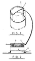
- Fig. 1 shows part of a cylindrical container drum made of mild steel having an end wall provided with a closure opening further illustrated in Fig. 2 as comprising a raised cylindrical section 1 of double thickness with a screw thread 2 on the cylindrical inner surface of the inner metal skin.
- the outer end of the cylindrical section 1 is thickened to provide a sealing surface 3 which is engaged by a sealing ring 4 of a conventional externally threaded bung 5 having an internal handle 6.
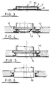
- the closure opening illustrated in Fig. 2 is made by first piercing, pressing and drawing the metal sheet constituted by the drum end wall (prior to fixing to the drum end in conventional manner) to form a cylindrical section 7 raised out of the plane of the end wall by a step 8 and terminating at its outer end in an annular flange 9 which partly closes the cylindrical section leaving a circular opening 10 around a central axis 11 (Fig. 3).
- the raised cylindrical section 7 is then surrounded by clamping supports 12 and a tool 13 is progressively introduced into the opening 10 so as to bend the flange 9 inwardly.
- a tool 13 is progressively introduced into the opening 10 so as to bend the flange 9 inwardly.
- Such deformation of the flange 9 requires a corresponding enlargement of the opening 10 which cannot be achieved without extension of the flange 9 along its circumferential dimension.
- Such extension is achieved by orbiting the tool 13 about the axis 11 while simultaneously rolling the frusto-conical tool surface on the flange 9 to achieve the necessary thinning of the metal in this region.
- the tool 13 When the flange 9 has been bent inwardly to an extent conforming to the shape of the tool 13, the tool 13 is replaced by a tool 14 which has a cylindrical working surface which, using the same rolling action as the tool 13, completes the inward deformation of the flange 9 and the attendant enlargement of the hole 10.
- the tool 14 also creates the shoulder 3 by pressing metal into a circular recess 15 in the clamping segments 12.
- the cylindrical section 1 is then completed by using a thread forming tool 16 which has an orbiting and rolling action like tool 14 but in this case is provided with a thread formation on its outer cylindrical periphery, the action of the tool 16 serving to impress said thread formation onto the internal surface of the cylindrical section.
- a thread forming tool 16 which has an orbiting and rolling action like tool 14 but in this case is provided with a thread formation on its outer cylindrical periphery, the action of the tool 16 serving to impress said thread formation onto the internal surface of the cylindrical section.
- Compensation for this difference may be accomplished by axial displacement of the tool amounting to the pitch of the thread times the ratio of the two diameters.
- the axial displacement of the forming tool may be achieved by allowing the tool to float freely or by providing an incremental movement of the tool spindle relative to tool rotation.
- the accumulative effects may be avoided by alternating the direction of rotation of the forming tool after each full revolution of the tool spindle.
Landscapes
- Engineering & Computer Science (AREA)
- Mechanical Engineering (AREA)
- Closures For Containers (AREA)
- Superconductors And Manufacturing Methods Therefor (AREA)
- Laminated Bodies (AREA)
- Transition And Organic Metals Composition Catalysts For Addition Polymerization (AREA)
- Secondary Cells (AREA)
- Rigid Containers With Two Or More Constituent Elements (AREA)
- Shaping Metal By Deep-Drawing, Or The Like (AREA)
- Containers Having Bodies Formed In One Piece (AREA)
Claims (6)
- Procédé de formation d'une ouverture cylindrique dans une feuille de tôle, comprenant les étapes de percer, presser et étirer la feuille de tôle afin de fournir une section cylindrique surélevée (1) possédant un axe (11) et partialment fermée à une extrémité par une bride annulaire (9), et de courber la bride (9) en la section cylindrique (1) tout en passant la bride (9) au rouleau de manière à permettre l'agrandissement nécessaire de celle-ci, caractérisé en ce que la courbure et l'agrandissement de la bride (9) sont obtenus par la mise en orbite d'un outil (13, 14) en engagement avec ladite bride (9) autour dudit axe (11) de la section cylindrique (11) et faisant rouler l'outil (13, 14) le long de la bride (9) autour d'un second axe décalé dudit axe de la section cylindrique.
- Procédé selon la revendication 1, caractérisé en ce que la feuille de tôle est une paroi d'extrémité d'un fût réservoir.
- Procédé selon la revendication 1 ou 2, caractérisé en ce que la section cylindrique surélevée (1) est supportée à l'extérieur pendant l'opération de courbure et de passage au rouleau.
- Procédé selon l'une quelconque des revendications précédentes, caractérise en ce que l'extrémité externe de la section cylindrique (1) est déformée radialement vers l'extérieur pendant l'opération de courbure et de passage au rouleau de manière à fournir une surface d'étanchéité (3) pour engagement par une bague d'étanchéité (4) d'un bondon (5).
- Procédé selon l'une quelconque des revendications précédentes, caractérisé en ce que la bride (9) courbée vers l'intérieur est pourvue d'un taraudage en faisant rouler un rouleau (16) cylindrique à filetage périphérique de diamètre inférieur à celui de la bride (9) de manière continue sur la surface de la bride en relation orbitale avec l'axe (11) de cylindre de la bride jusqu'à ce que la surface soit déformée en une configuration complémentaire à taraudage.
- Procédé selon la revendication 5, caractérisé en ce que le rouleau (16) à filetage est déplacé ou permis d'être déplacé axialement de manière à compenser la différence de pas entre les filets de filetage et de taraudage.
Applications Claiming Priority (5)
| Application Number | Priority Date | Filing Date | Title |
|---|---|---|---|
| GB898916630A GB8916630D0 (en) | 1989-07-20 | 1989-07-20 | Improvements in or relating to metal deformation |
| GB8916630 | 1989-07-20 | ||
| GB898921901A GB8921901D0 (en) | 1989-09-28 | 1989-09-28 | Improvements in or relating to metal deformation |
| GB8921901 | 1989-09-28 | ||
| PCT/GB1990/001123 WO1991001188A1 (fr) | 1989-07-20 | 1990-07-20 | Amelioration relative a un procede de deformation du metal |
Publications (2)
| Publication Number | Publication Date |
|---|---|
| EP0483207A1 EP0483207A1 (fr) | 1992-05-06 |
| EP0483207B1 true EP0483207B1 (fr) | 1994-09-14 |
Family
ID=26295638
Family Applications (1)
| Application Number | Title | Priority Date | Filing Date |
|---|---|---|---|
| EP90910821A Expired - Lifetime EP0483207B1 (fr) | 1989-07-20 | 1990-07-20 | Amelioration relative a un procede de deformation du metal |
Country Status (5)
| Country | Link |
|---|---|
| EP (1) | EP0483207B1 (fr) |
| AT (1) | ATE111386T1 (fr) |
| AU (1) | AU6056090A (fr) |
| DE (1) | DE69012569T2 (fr) |
| WO (1) | WO1991001188A1 (fr) |
Families Citing this family (1)
| Publication number | Priority date | Publication date | Assignee | Title |
|---|---|---|---|---|
| BR9506203A (pt) * | 1994-05-20 | 1996-04-23 | Tecnocar Srl | Processo para manufaturação de um componente único de tampa para filtros de veiculos especialmente filtros de óleo e produção da tampa através deste processo |
Family Cites Families (3)
| Publication number | Priority date | Publication date | Assignee | Title |
|---|---|---|---|---|
| US2460721A (en) * | 1945-07-07 | 1949-02-01 | Inland Steel Co | Method of forming bungs in metallic plates |
| US2493933A (en) * | 1945-07-07 | 1950-01-10 | Inland Steel Co | Machine for forming threaded openings |
| DE3050452A1 (en) * | 1980-06-26 | 1982-08-12 | V Chemeris | Method of obtaining butt-end wall with concentric recess in a tubular workpiece |
-
1990
- 1990-07-20 AT AT90910821T patent/ATE111386T1/de not_active IP Right Cessation
- 1990-07-20 AU AU60560/90A patent/AU6056090A/en not_active Abandoned
- 1990-07-20 EP EP90910821A patent/EP0483207B1/fr not_active Expired - Lifetime
- 1990-07-20 DE DE69012569T patent/DE69012569T2/de not_active Expired - Fee Related
- 1990-07-20 WO PCT/GB1990/001123 patent/WO1991001188A1/fr not_active Ceased
Also Published As
| Publication number | Publication date |
|---|---|
| ATE111386T1 (de) | 1994-09-15 |
| EP0483207A1 (fr) | 1992-05-06 |
| AU6056090A (en) | 1991-02-22 |
| DE69012569D1 (de) | 1994-10-20 |
| DE69012569T2 (de) | 1995-04-20 |
| WO1991001188A1 (fr) | 1991-02-07 |
Similar Documents
| Publication | Publication Date | Title |
|---|---|---|
| US4341103A (en) | Spin-necker flanger for beverage containers | |
| JP3053219B2 (ja) | ハブを有する伝動装置部材のハブを切削によらずに製造する方法 | |
| US3833984A (en) | Process and arrangement for double flanging of pipes | |
| US4888862A (en) | Method for installing bearing rings | |
| US5297411A (en) | Method of forming threaded opening | |
| SE426145B (sv) | Forfarande for formning av en endvegg med ett koncentriskt urtag i ett rorformigt arbetsstycke | |
| US3962899A (en) | Method and apparatus for making an eccentric locking collar | |
| WO1991001188A1 (fr) | Amelioration relative a un procede de deformation du metal | |
| EP0235881B1 (fr) | Procédé pour la fabrication d'un générateur d'ondes pour une transmission à ondes de tension | |
| JPH0366433A (ja) | 円筒形金属缶体の開端部変形の方法および装置 | |
| EP0065842A1 (fr) | Attache des couvercles sur des boîtes à symétrie de révolution | |
| JP2754070B2 (ja) | ロープ受けドラムおよびその製造方法 | |
| US8042370B2 (en) | Flow formed gear | |
| CN1241697C (zh) | 不用心轴的薄金属轴圈的成型方法 | |
| GB2083872A (en) | Method for the swarfless production of a bearing bush | |
| RU2085318C1 (ru) | Устройство для получения винтовой канавки на трубной заготовке | |
| US2243138A (en) | Device for forming screw closure caps and similar articles | |
| US3254619A (en) | Method of producing an inturned bead metal cap in a rotary type die | |
| JP2018176181A (ja) | ボトル缶の製造方法 | |
| JPH0347935B2 (fr) | ||
| SU1174140A1 (ru) | Устройство дл накатки зубчатых колес | |
| WO2001064410A1 (fr) | Foret tubulaire | |
| SU680793A1 (ru) | Инструмент дл поперечно-винтовой прокатки штучных кольцевых заготовок | |
| RU1787625C (ru) | Способ раздачи конца трубы | |
| JPH07284857A (ja) | 偏心ダイスを使用した部分コルゲート管の製造方法 |
Legal Events
| Date | Code | Title | Description |
|---|---|---|---|
| PUAI | Public reference made under article 153(3) epc to a published international application that has entered the european phase |
Free format text: ORIGINAL CODE: 0009012 |
|
| 17P | Request for examination filed |
Effective date: 19920219 |
|
| AK | Designated contracting states |
Kind code of ref document: A1 Designated state(s): AT BE CH DE DK ES FR GB IT LI LU NL SE |
|
| 17Q | First examination report despatched |
Effective date: 19930119 |
|
| GRAA | (expected) grant |
Free format text: ORIGINAL CODE: 0009210 |
|
| AK | Designated contracting states |
Kind code of ref document: B1 Designated state(s): AT BE CH DE DK ES FR GB IT LI LU NL SE |
|
| PG25 | Lapsed in a contracting state [announced via postgrant information from national office to epo] |
Ref country code: NL Effective date: 19940914 Ref country code: LI Effective date: 19940914 Ref country code: ES Free format text: THE PATENT HAS BEEN ANNULLED BY A DECISION OF A NATIONAL AUTHORITY Effective date: 19940914 Ref country code: DK Effective date: 19940914 Ref country code: CH Effective date: 19940914 Ref country code: BE Effective date: 19940914 Ref country code: AT Effective date: 19940914 |
|
| REF | Corresponds to: |
Ref document number: 111386 Country of ref document: AT Date of ref document: 19940915 Kind code of ref document: T |
|
| REF | Corresponds to: |
Ref document number: 69012569 Country of ref document: DE Date of ref document: 19941020 |
|
| ITF | It: translation for a ep patent filed | ||
| PG25 | Lapsed in a contracting state [announced via postgrant information from national office to epo] |
Ref country code: SE Effective date: 19941214 |
|
| REG | Reference to a national code |
Ref country code: CH Ref legal event code: PL |
|
| ET | Fr: translation filed | ||
| NLV1 | Nl: lapsed or annulled due to failure to fulfill the requirements of art. 29p and 29m of the patents act | ||
| PLBE | No opposition filed within time limit |
Free format text: ORIGINAL CODE: 0009261 |
|
| STAA | Information on the status of an ep patent application or granted ep patent |
Free format text: STATUS: NO OPPOSITION FILED WITHIN TIME LIMIT |
|
| PG25 | Lapsed in a contracting state [announced via postgrant information from national office to epo] |
Ref country code: LU Free format text: LAPSE BECAUSE OF NON-PAYMENT OF DUE FEES Effective date: 19950731 |
|
| 26N | No opposition filed | ||
| PGFP | Annual fee paid to national office [announced via postgrant information from national office to epo] |
Ref country code: FR Payment date: 19960709 Year of fee payment: 7 |
|
| PGFP | Annual fee paid to national office [announced via postgrant information from national office to epo] |
Ref country code: GB Payment date: 19960711 Year of fee payment: 7 |
|
| PGFP | Annual fee paid to national office [announced via postgrant information from national office to epo] |
Ref country code: DE Payment date: 19960726 Year of fee payment: 7 |
|
| PG25 | Lapsed in a contracting state [announced via postgrant information from national office to epo] |
Ref country code: GB Free format text: LAPSE BECAUSE OF NON-PAYMENT OF DUE FEES Effective date: 19970720 |
|
| GBPC | Gb: european patent ceased through non-payment of renewal fee |
Effective date: 19970720 |
|
| PG25 | Lapsed in a contracting state [announced via postgrant information from national office to epo] |
Ref country code: FR Free format text: LAPSE BECAUSE OF NON-PAYMENT OF DUE FEES Effective date: 19980331 |
|
| PG25 | Lapsed in a contracting state [announced via postgrant information from national office to epo] |
Ref country code: DE Free format text: LAPSE BECAUSE OF NON-PAYMENT OF DUE FEES Effective date: 19980401 |
|
| REG | Reference to a national code |
Ref country code: FR Ref legal event code: ST |
|
| PG25 | Lapsed in a contracting state [announced via postgrant information from national office to epo] |
Ref country code: IT Free format text: LAPSE BECAUSE OF NON-PAYMENT OF DUE FEES;WARNING: LAPSES OF ITALIAN PATENTS WITH EFFECTIVE DATE BEFORE 2007 MAY HAVE OCCURRED AT ANY TIME BEFORE 2007. THE CORRECT EFFECTIVE DATE MAY BE DIFFERENT FROM THE ONE RECORDED. Effective date: 20050720 |