EP0483301B1 - Kraftstoffversorgungssystem für eine brennkraftmaschine - Google Patents
Kraftstoffversorgungssystem für eine brennkraftmaschine Download PDFInfo
- Publication number
- EP0483301B1 EP0483301B1 EP91907440A EP91907440A EP0483301B1 EP 0483301 B1 EP0483301 B1 EP 0483301B1 EP 91907440 A EP91907440 A EP 91907440A EP 91907440 A EP91907440 A EP 91907440A EP 0483301 B1 EP0483301 B1 EP 0483301B1
- Authority
- EP
- European Patent Office
- Prior art keywords
- fuel
- supply system
- return flow
- flow rate
- pressure
- Prior art date
- Legal status (The legal status is an assumption and is not a legal conclusion. Google has not performed a legal analysis and makes no representation as to the accuracy of the status listed.)
- Expired - Lifetime
Links
- 238000002485 combustion reaction Methods 0.000 title claims abstract description 17
- 239000000446 fuel Substances 0.000 claims abstract description 86
- 230000001133 acceleration Effects 0.000 claims description 2
- 238000002347 injection Methods 0.000 description 5
- 239000007924 injection Substances 0.000 description 5
- 239000002828 fuel tank Substances 0.000 description 3
- 230000015572 biosynthetic process Effects 0.000 description 1
- 230000003993 interaction Effects 0.000 description 1
- 239000000243 solution Substances 0.000 description 1
- 230000007704 transition Effects 0.000 description 1
- XLYOFNOQVPJJNP-UHFFFAOYSA-N water Substances O XLYOFNOQVPJJNP-UHFFFAOYSA-N 0.000 description 1
Images

Classifications
-
- F—MECHANICAL ENGINEERING; LIGHTING; HEATING; WEAPONS; BLASTING
- F02—COMBUSTION ENGINES; HOT-GAS OR COMBUSTION-PRODUCT ENGINE PLANTS
- F02D—CONTROLLING COMBUSTION ENGINES
- F02D41/00—Electrical control of supply of combustible mixture or its constituents
- F02D41/02—Circuit arrangements for generating control signals
- F02D41/04—Introducing corrections for particular operating conditions
- F02D41/06—Introducing corrections for particular operating conditions for engine starting or warming up
- F02D41/062—Introducing corrections for particular operating conditions for engine starting or warming up for starting
- F02D41/065—Introducing corrections for particular operating conditions for engine starting or warming up for starting at hot start or restart
-
- F—MECHANICAL ENGINEERING; LIGHTING; HEATING; WEAPONS; BLASTING
- F02—COMBUSTION ENGINES; HOT-GAS OR COMBUSTION-PRODUCT ENGINE PLANTS
- F02D—CONTROLLING COMBUSTION ENGINES
- F02D41/00—Electrical control of supply of combustible mixture or its constituents
- F02D41/30—Controlling fuel injection
- F02D41/3082—Control of electrical fuel pumps
-
- F—MECHANICAL ENGINEERING; LIGHTING; HEATING; WEAPONS; BLASTING
- F02—COMBUSTION ENGINES; HOT-GAS OR COMBUSTION-PRODUCT ENGINE PLANTS
- F02M—SUPPLYING COMBUSTION ENGINES IN GENERAL WITH COMBUSTIBLE MIXTURES OR CONSTITUENTS THEREOF
- F02M51/00—Fuel-injection apparatus characterised by being operated electrically
- F02M51/02—Fuel-injection apparatus characterised by being operated electrically specially for low-pressure fuel-injection
-
- F—MECHANICAL ENGINEERING; LIGHTING; HEATING; WEAPONS; BLASTING
- F02—COMBUSTION ENGINES; HOT-GAS OR COMBUSTION-PRODUCT ENGINE PLANTS
- F02M—SUPPLYING COMBUSTION ENGINES IN GENERAL WITH COMBUSTIBLE MIXTURES OR CONSTITUENTS THEREOF
- F02M69/00—Low-pressure fuel-injection apparatus ; Apparatus with both continuous and intermittent injection; Apparatus injecting different types of fuel
- F02M69/16—Low-pressure fuel-injection apparatus ; Apparatus with both continuous and intermittent injection; Apparatus injecting different types of fuel characterised by means for metering continuous fuel flow to injectors or means for varying fuel pressure upstream of continuously or intermittently operated injectors
- F02M69/18—Low-pressure fuel-injection apparatus ; Apparatus with both continuous and intermittent injection; Apparatus injecting different types of fuel characterised by means for metering continuous fuel flow to injectors or means for varying fuel pressure upstream of continuously or intermittently operated injectors the means being metering valves throttling fuel passages to injectors or by-pass valves throttling overflow passages, the metering valves being actuated by a device responsive to the engine working parameters, e.g. engine load, speed, temperature or quantity of air
Definitions
- the invention relates to a fuel supply system for an internal combustion engine with an electric fuel pump, a fuel pressure regulator and a fuel metering system.
- DE-OS 36 08 522 also describes a fuel injection system with a specially designed pressure regulator, in which an additional spring can engage by means of an electromagnet, in order to thereby obtain a controllable fuel pressure depending on the operating range of the internal combustion engine.
- U.S. Patent 4,791,905 discloses a so-called on-demand electromagnetic fuel pump.
- signals relating to air throughput in the intake manifold, speed, pressure in the intake manifold, water temperature and battery voltage are processed in a control unit, which in turn determines the control of the fuel pump with and without a series resistor. This achieves a large delivery rate with a high fuel requirement and a corresponding reduction in the delivery rate with a lower fuel requirement depending on the operating parameters of the internal combustion engine.
- US Pat. No. 3,822,677 shows a fuel pump control system with a variable energy supply for the fuel pump depending on the fuel requirement.
- a fuel supply system in an internal combustion engine in which an electric fuel pump delivers fuel from the fuel tank to the fuel rail in the usual way.
- a pressure regulator arranged in the fuel return line keeps the fuel pressure constant.
- a controllable valve is present in the fuel return line between the pressure regulator and the fuel tank, which valve can be closed by a control device if the control device detects that low temperatures are present when the internal combustion engine is started and a so-called cold start occurs. By closing this valve in the return line, the fuel return is prevented and an increased pressure is established in the fuel rail, which remains built up until a transition to the normal operating condition is detected.
- the disadvantage of this fuel supply system is that the fuel return line is completely blocked, so that excess fuel cannot get back into the tank.
- the object of the invention is therefore to create a system with high flexibility.
- the fuel supply system according to the invention for an internal combustion engine enables the provision of different amounts of fuel with different ones using relatively simple means
- Fuel pressures in the individual operating states of the internal combustion engine In addition to efficient and fuel-oriented fuel delivery by the fuel pump, an ideal pressure curve is also achieved, in order to ensure an optimal fuel supply, especially during the starting event, even when the internal combustion engine is hot.
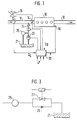
- FIG. 1 shows an overview of a fuel supply system
- FIG. 2 each shows a pressure regulator characteristic curve according to the prior art and according to the solution according to the invention
- FIG. 3 shows a supplementary circuit for the fuel pressure regulator to achieve the desired pressure curve.
- FIG. 1 shows a rough overview of a fuel supply system in an internal combustion engine with spark ignition.
- the internal combustion engine itself is designated by 10, an air intake pipe by 11 and an exhaust pipe by 12.
- An air flow meter 13 and a throttle valve 14 which can be actuated by an accelerator pedal 15.
- An electrical control unit 20 receives signals from the air quantity sensor 13, from the speed sensor 16 and, if appropriate, further sensors and outputs signals on the output side both to a fuel pump 23 and to at least one electromagnetic injection valve 24.
- the fuel pump 21 receives the fuel from a fuel tank 21 and conveys it to the injection valve 24.
- a pressure regulator 25 downstream of the fuel pump 23 serves the Keep fuel pressure at a desired level. The fuel quantity conveyed by the fuel pump 23 and lying above the requirement then returns to the tank 21 via a return line.
- FIG. 1 The overview of a fuel supply system shown in FIG. 1 corresponds in principle to the prior art.
- Figure 2 shows two pressure regulator characteristics.
- the characteristic curve according to FIG. 2a corresponds to that of the prior art.
- the pressure curve is plotted against the amount of fuel.
- the pressure control characteristic curve according to the prior art is designed in such a way that it remains at a specific setpoint PKsetpoint above the minimum flow rate Qmin.
- FIG. 2b shows a modified pressure regulator characteristic curve with an essentially constant pressure value between the minimum and maximum value for the return flow and an increased fuel pressure in the event that the return flow rises above Q max .
- the increased pressure value can be used to reduce the formation of vapor bubbles during a hot start.
- the provision of an increased fuel pressure can also be expedient during the post-starting situation, particularly when there has been a hot starting situation. The same applies in the case of acceleration.
- the demand control of the fuel pump is expediently carried out by means of a cyclical control, which is known as such from the prior art. They are used in normal operation to ensure that the return flow does not leave the interval limited by Q min and Q max .
- the design of the fuel pressure regulator to achieve the desired pressure curve is not a problem for the person skilled in the art; the design of the pressure regulator is even simplified since the constant pressure interval no longer has to be as large.
- the fuel pressure regulator can be designed in such a way that an increased fuel pressure occurs with an increasing return flow quantity. This can be achieved by appropriately dimensioning the individual parts of the pressure regulator, in particular the spring located in the pressure regulator or via the shape of the return line.
- FIG. 3 finally shows a throttled return line from the pressure regulator 25 to the tank 21, a throttle 26 with a valve 27 connected in parallel being provided in the return line itself and this valve 27 being electromagnetically controllable from the control unit 20 of FIG. 1.
- the variation of the return line known per se to the state of the art can be ideally supplemented with a demand control of the fuel pump in order to achieve an optimal fuel supply to the internal combustion engine in all operating conditions.
Landscapes
- Engineering & Computer Science (AREA)
- Chemical & Material Sciences (AREA)
- Combustion & Propulsion (AREA)
- Mechanical Engineering (AREA)
- General Engineering & Computer Science (AREA)
- Electrical Control Of Air Or Fuel Supplied To Internal-Combustion Engine (AREA)
- Fuel-Injection Apparatus (AREA)
Applications Claiming Priority (3)
| Application Number | Priority Date | Filing Date | Title |
|---|---|---|---|
| DE4016055 | 1990-05-18 | ||
| DE4016055A DE4016055A1 (de) | 1990-05-18 | 1990-05-18 | Kraftstoffversorgungssystem fuer eine brennkraftmaschine |
| PCT/DE1991/000315 WO1991018196A1 (de) | 1990-05-18 | 1991-04-18 | Kraftstoffversorgungssystem für eine brennkraftmaschine |
Publications (2)
| Publication Number | Publication Date |
|---|---|
| EP0483301A1 EP0483301A1 (de) | 1992-05-06 |
| EP0483301B1 true EP0483301B1 (de) | 1995-07-26 |
Family
ID=6406740
Family Applications (1)
| Application Number | Title | Priority Date | Filing Date |
|---|---|---|---|
| EP91907440A Expired - Lifetime EP0483301B1 (de) | 1990-05-18 | 1991-04-18 | Kraftstoffversorgungssystem für eine brennkraftmaschine |
Country Status (4)
| Country | Link |
|---|---|
| EP (1) | EP0483301B1 (ja) |
| JP (1) | JP3224537B2 (ja) |
| DE (2) | DE4016055A1 (ja) |
| WO (1) | WO1991018196A1 (ja) |
Families Citing this family (10)
| Publication number | Priority date | Publication date | Assignee | Title |
|---|---|---|---|---|
| FR2711734B1 (fr) * | 1993-10-29 | 1995-11-24 | Renault | Procédé de commande d'une pompe à carburant de moteur à combustion interne. |
| DE4344572C1 (de) * | 1993-12-24 | 1995-04-27 | Bosch Gmbh Robert | Einrichtung zur Kraftstoffversorgung |
| DE4344775A1 (de) * | 1993-12-28 | 1995-06-29 | Technoflow Tube Systems Gmbh | Kraftstoff-Versorgungssystem für ein Kraftfahrzeug mit Ottomotor |
| DE4344776A1 (de) * | 1993-12-28 | 1995-06-29 | Technoflow Tube Systems Gmbh | Kraftstoff-Versorgungssystem für ein Kraftfahrzeug mit Ottomotor |
| JPH08109862A (ja) * | 1994-10-11 | 1996-04-30 | Nippondenso Co Ltd | 燃料供給装置 |
| WO1998027333A1 (en) * | 1996-12-17 | 1998-06-25 | Siemens Automotive Corporation | Fuel supply system for a vehicle |
| DE19818421B4 (de) * | 1998-04-24 | 2017-04-06 | Robert Bosch Gmbh | Kraftstoffversorgungsanlage einer Brennkraftmaschine |
| EP2096289A1 (en) | 2008-02-29 | 2009-09-02 | Magneti Marelli Powertrain S.p.A. | Control method of an electronic injection fuel feeding system |
| JP5779936B2 (ja) * | 2011-03-28 | 2015-09-16 | トヨタ自動車株式会社 | 燃料供給システム |
| JP5827060B2 (ja) * | 2011-08-01 | 2015-12-02 | トヨタ自動車株式会社 | 圧力制御装置および燃料供給装置 |
Family Cites Families (4)
| Publication number | Priority date | Publication date | Assignee | Title |
|---|---|---|---|---|
| DE1576482A1 (de) * | 1967-09-13 | 1970-05-06 | Bosch Gmbh Robert | Kraftstoffeinspritzanlage |
| US4747386A (en) * | 1986-05-02 | 1988-05-31 | Toyota Jidosha Kabushiki Kaisha | Method and apparatus for augmenting fuel injection on hot restart of engine |
| EP0248411B1 (en) * | 1986-06-03 | 1992-03-25 | Mitsubishi Denki Kabushiki Kaisha | Fuel pressure regulator |
| FR2612257B1 (fr) | 1987-03-10 | 1989-06-09 | Renault | Circuit de carburant d'un systeme d'injection electronique pour moteur a combustion interne |
-
1990
- 1990-05-18 DE DE4016055A patent/DE4016055A1/de not_active Withdrawn
-
1991
- 1991-04-18 JP JP50674691A patent/JP3224537B2/ja not_active Expired - Fee Related
- 1991-04-18 EP EP91907440A patent/EP0483301B1/de not_active Expired - Lifetime
- 1991-04-18 DE DE59106084T patent/DE59106084D1/de not_active Expired - Fee Related
- 1991-04-18 WO PCT/DE1991/000315 patent/WO1991018196A1/de not_active Ceased
Also Published As
| Publication number | Publication date |
|---|---|
| WO1991018196A1 (de) | 1991-11-28 |
| EP0483301A1 (de) | 1992-05-06 |
| JP3224537B2 (ja) | 2001-10-29 |
| DE4016055A1 (de) | 1991-11-21 |
| JPH05500099A (ja) | 1993-01-14 |
| DE59106084D1 (de) | 1995-08-31 |
Similar Documents
| Publication | Publication Date | Title |
|---|---|---|
| DE19818421B4 (de) | Kraftstoffversorgungsanlage einer Brennkraftmaschine | |
| EP1180595B2 (de) | Kraftstoffversorgungsanlage | |
| DE69905685T2 (de) | Kraftstoffeinspritzvorrichtung der Akkumulatorgattung | |
| EP1042608A1 (de) | Kraftstoffversorgungsanlage einer brennkraftmaschine | |
| DE2715587A1 (de) | Kraftstoffversorgungseinrichtung | |
| EP0483301B1 (de) | Kraftstoffversorgungssystem für eine brennkraftmaschine | |
| EP1108862B1 (de) | Verfahren und Vorrichtung zum Reduzieren schädlicher Bestandteile im Abgas einer Brennkraftmaschine | |
| DE4122346A1 (de) | Hochdruck-kraftstoffeinspritzeinrichtung fuer eine brennkraftmaschine | |
| EP0733797A2 (de) | Brennstoffversorgungssystem für Brennkraftmaschinen | |
| EP0974005B1 (de) | Kraftstoff-fördermodul für eine benzindirekteinspeisung einer brennkraftmaschine mit einem ventil | |
| EP1576272B1 (de) | Rücklauffreies kraftstoffversorgungssystem | |
| DE3203179A1 (de) | Verfahren zur gemischbildung fuer gemischverdichtende brennkraftmaschinen und kraftstoffversorgungsanlage zur durchfuehrung des verfahrens | |
| DE3435170C2 (de) | Verfahren zur Steuerung eines Luft-Kraftstoff-Ansaugsystems mit veränderlichem Drall und mit einem geraden sowie schraubenförmigen Ansaugkanal für eine Brennkraftmaschine | |
| DE69415140T2 (de) | STEUERSYSTEM FüR EIN HOCHDRUCK-KRAFTSTOFFEINSPRITZSYSTEM FüR EINE BRENNKRAFTMASCHINE | |
| DE4312331A1 (de) | Kraftstoffeinspritzanlage für einen Verbrennungsmotor | |
| DE102007000323A1 (de) | Kraftstoffeinspritzsteuergerät | |
| DE2621555A1 (de) | Kraftstoffeinspritzanlage | |
| DE19510497A1 (de) | Brennstoffversorgungssystem für Brennkraftmaschinen | |
| WO1991019892A1 (de) | Verfahren zur einstellung der kraftstoffördermenge einer brennkraftmaschine | |
| EP0237754A1 (de) | Verfahren zum Steuern einer Kraftstoffeinspritzanlage und Kraftstoffeinspritzanlage | |
| DE102004060905A1 (de) | Verfahren zur Steuerung einer Brennkraftmaschine der ein gasförmiger Brennstoff zugeführt wird und Vorrichtung zur Druckreduzierung eines Gases | |
| DE19946908A1 (de) | Verfahren zum Abbau des Rail-Drucks in einem Common-Rail-System für Brennkraftmaschinen | |
| DE3211680A1 (de) | Kraftstoffeinspritzsystem fuer brennkraftmaschinen | |
| DE60012331T2 (de) | Vorrichtung zum Steuern der Kraftstoffeinspritzung | |
| DE3324677C2 (de) | Steuersystem für eine ergänzende Kraftstoffzumessung im Beschleunigungsfall für eine Brennkraftmaschine |
Legal Events
| Date | Code | Title | Description |
|---|---|---|---|
| PUAI | Public reference made under article 153(3) epc to a published international application that has entered the european phase |
Free format text: ORIGINAL CODE: 0009012 |
|
| 17P | Request for examination filed |
Effective date: 19911111 |
|
| AK | Designated contracting states |
Kind code of ref document: A1 Designated state(s): DE GB |
|
| 17Q | First examination report despatched |
Effective date: 19940518 |
|
| GRAA | (expected) grant |
Free format text: ORIGINAL CODE: 0009210 |
|
| AK | Designated contracting states |
Kind code of ref document: B1 Designated state(s): DE GB |
|
| REF | Corresponds to: |
Ref document number: 59106084 Country of ref document: DE Date of ref document: 19950831 |
|
| GBT | Gb: translation of ep patent filed (gb section 77(6)(a)/1977) |
Effective date: 19951010 |
|
| PLBE | No opposition filed within time limit |
Free format text: ORIGINAL CODE: 0009261 |
|
| STAA | Information on the status of an ep patent application or granted ep patent |
Free format text: STATUS: NO OPPOSITION FILED WITHIN TIME LIMIT |
|
| 26N | No opposition filed | ||
| REG | Reference to a national code |
Ref country code: GB Ref legal event code: IF02 |
|
| PGFP | Annual fee paid to national office [announced via postgrant information from national office to epo] |
Ref country code: GB Payment date: 20050407 Year of fee payment: 15 |
|
| PGFP | Annual fee paid to national office [announced via postgrant information from national office to epo] |
Ref country code: DE Payment date: 20050617 Year of fee payment: 15 |
|
| PG25 | Lapsed in a contracting state [announced via postgrant information from national office to epo] |
Ref country code: GB Free format text: LAPSE BECAUSE OF NON-PAYMENT OF DUE FEES Effective date: 20060418 |
|
| PG25 | Lapsed in a contracting state [announced via postgrant information from national office to epo] |
Ref country code: DE Free format text: LAPSE BECAUSE OF NON-PAYMENT OF DUE FEES Effective date: 20061101 |
|
| GBPC | Gb: european patent ceased through non-payment of renewal fee |
Effective date: 20060418 |