EP0483362A1 - Systeme mesureur de la longueur d'une feuille - Google Patents
Systeme mesureur de la longueur d'une feuille Download PDFInfo
- Publication number
- EP0483362A1 EP0483362A1 EP91908182A EP91908182A EP0483362A1 EP 0483362 A1 EP0483362 A1 EP 0483362A1 EP 91908182 A EP91908182 A EP 91908182A EP 91908182 A EP91908182 A EP 91908182A EP 0483362 A1 EP0483362 A1 EP 0483362A1
- Authority
- EP
- European Patent Office
- Prior art keywords
- sheet
- cameras
- corners
- dimensions
- absolute coordinates
- Prior art date
- Legal status (The legal status is an assumption and is not a legal conclusion. Google has not performed a legal analysis and makes no representation as to the accuracy of the status listed.)
- Granted
Links
Images





Classifications
-
- G—PHYSICS
- G01—MEASURING; TESTING
- G01B—MEASURING LENGTH, THICKNESS OR SIMILAR LINEAR DIMENSIONS; MEASURING ANGLES; MEASURING AREAS; MEASURING IRREGULARITIES OF SURFACES OR CONTOURS
- G01B11/00—Measuring arrangements characterised by the use of optical techniques
- G01B11/02—Measuring arrangements characterised by the use of optical techniques for measuring length, width or thickness
- G01B11/022—Measuring arrangements characterised by the use of optical techniques for measuring length, width or thickness by means of tv-camera scanning
-
- G—PHYSICS
- G01—MEASURING; TESTING
- G01B—MEASURING LENGTH, THICKNESS OR SIMILAR LINEAR DIMENSIONS; MEASURING ANGLES; MEASURING AREAS; MEASURING IRREGULARITIES OF SURFACES OR CONTOURS
- G01B11/00—Measuring arrangements characterised by the use of optical techniques
- G01B11/02—Measuring arrangements characterised by the use of optical techniques for measuring length, width or thickness
- G01B11/04—Measuring arrangements characterised by the use of optical techniques for measuring length, width or thickness specially adapted for measuring length or width of objects while moving
Definitions
- This invention relates to a system for measuring dimensions of sheets moving on a transferring line and also relates to a sheet dimension measurement system enabling to inspect dimensions and shapes of sheets.
- the sheet dimension measurement system of the first invention comprises of:
- a sheet dimension measurement system comprising: a plurality of camera installed above a transferring line transferring sheets, so as to keep each of four sheet corners within a field of view of each of the cameras and to be movable in accordance with sheet dimensions, a plurality of flashing devices, each installed with an angle against an optical axis of each of the cameras, so as to produce shadows of four sheet corners for the cameras and to be movable interlocking with the cameras, a plurality of corner detecting sections for detecting absolute coordinates of sheet corners based on differences in brightness of standstill pictures taken by the cameras, and a sheet dimension computing section for calculating lengths, widths and diagonal dimensions of sheets based on the detected absolute coordinates of four sheet corners.
- the sheet dimension measurement system of the second invention comprises: A sheet dimension measurement system, comprising: a plurality of first cameras installed above a transferring line transferring sheets, so as to keep each of four sheet corners within a field of view of each of the first cameras and to be movable in accordance with sheet dimensions, a plurality of second cameras installed so as to keep each of four sheet sides within a field of view of each of the second cameras and to be movable in accordance with sheet dimensions, a plurality of first flashing devices, each installed with an angle against an optical axis of each of the second cameras, so as to produce shadows of four sheet corners for the first cameras and to be movable interlocking with the first cameras, a plurality of second flashing devices, each installed with an angle against an optical axis of each of the second cameras, so as to produce shadows of four sheet sides for the second cameras and to be movable interlocking with the second cameras, a plurality of corner detecting sections for detecting absolute coordinates of four sheet corners based on differences in brightness of standstill
- Figs 1A and 1B are plan and side view of the sheet dimension measurement system of the first invention.
- Fig. 2 shows the overall system construction of the embodiment shown in Fig. 1.
- Fig.3 is a functional block diagram of video data processing unit.
- Figs.4A, 4B and 4C are drawings illustrating the algorithm to obtain absolute coordinates of sheet corners.
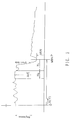
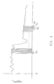
- Figs.5 and 6 are drawings illustrating the algorithm to obtain positions of sheet sides.
- Fig.7 is a drawing showing sheet dimensions to be measured.
- Fig.8 is a plan view of a practice example of the second invention.
- Fig.9 shows the system construction of the embodiment shown in Fig.8.
- Fig.10 is a block diagram of video data processing unit.
- Fig.11 is a drawing illustrating the algorithm to obtain absolute coordinates of sheet side centers.
- Fig.12 is a drawing illustrating transformation of sheet sides.
- Figs.1A and 1B are plan and side view showing the arrangement of CCD based cameras and flashing devices of an embodiment where the sheet dimension measurement system of the first invention is put into practice.
- a transferring line 10 transferring sheet 9, like a conveyor system, CCD based cameras 1, 2, 3 and 4 are installed at positions enabling to take standstill pictures of four corners of a sheet 9 being transferred in the direction of an arrow A.
- each of flashing devices 5, 6, 7 and 8 Adjacently to each of the cameras, each of flashing devices 5, 6, 7 and 8 is installed, with an angle, for example, with an angle of 45°, against the optical axis of each camera, so that shadows of sheet corners are produced when flash light is emitted. These shadows are essential for detection of sheet corners as described below.
- a sensor 11 is provided above the transferring line 10, to detect front edge of sheet 9.
- the cameras and flashing devices are automatically movable to appropriate positions in accordance with sheet dimensions to be measured. Such mechanism can be realized easily with currently available usual technologies.
- Fig.2 is a drawing showing the overall system configuration of this embodiment.
- the sheet dimension measurement system of this embodiment consists of the aforementioned CCD based cameras 1, 2, 3 and 4, flashing devices 5, 6, 7 and 8, and sheet front edge detecting sensor 11 as well as sensor amplifier 12, flashing device amplifier 13, frame memories 14, 15, 16 and 17, video data processing unit 18, and monitors 21, 22, 23 and 24.
- Fig.3 is a block diagram showing the functions of video data processing unit 18.
- the video data processing unit consists of corner detecting sections 31, 32, 33 and 34 to detect absolute coordinates of sheet corners based on light-and-shade pictures sent from the frame memories, and sheet dimension section 35 to calculate sheet dimensions based on absolute coordinate sent from these detecting sections.
- a trigger input is sent from the sensor amplifier 12 to the flashing amplifier 13, and the flashing devices 5 to 8 emit light.
- the standstill pictures of four sheet corners are taken by the cameras 1 to 4, the standstill pictures are sent to the frame memories 14 to 17.
- the corner detecting sections 31, 32, 33 and 34 in the video data processing unit 18 analyze absolute coordinates of sheet corners on the field of view of the cameras, from the light-and-shade pictures of 256 tone levels stored in the frame memories.
- the algorithm for this analysis is explained below.
- the detection of sheet corners is carried out by utilizing shadow 37 of sheet 9 produced by flash light within the field of view of the camera 36, as shown in Fig.4A.
- the darkest portions are the shadows of sheet corners, and the sheet corners are detected based on these shadows. This method is explained below, referring to Figs.4B and 4C.
- the standstill pictures taken by each camera can be monitored by each of the monitors 21 to 24, With the aforementioned procedures, the points x1 to x5 and y1 to y5 can be obtained.
- the algorithm to obtain these points is explained below, referring to Fig.5, which shows brightness distribution of one feed in the direction of X-axis or Y-axis, provided that sheet is brighter than conveyor belt of the transferring line.
- the aforementioned algorithm to obtain absolute coordinates of sheet corners is implemented in each of the corner detecting section 31, 32, 33 and 34 in Fig.3, and the obtained absolute coordinates of corners are sent to the sheet dimension computing section 35.
- a trigger input is sent from the sensor amplifier 12 to each corner detecting section as process start command.
- the sheet dimensions shown in Fig.7 namely the lengths LD and LW, the widths WT and WB, and the diagonal dimensions TD and TW, are calculated.
- the absolute coordinates of the lends center of each camera must be measured in advance and must be input to the sheet dimension computing section as parameters.
- the calculated sheet dimensions are sent to appropriate display media and are displayed. It is also possible to compare the obtained sheet dimensions with standard dimensions and to notify incorrect sheet dimensions, for example, by raising alarm, when any deviations from the standard values are found.
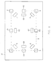
- Fig.8 is a plan view to show arrangement of CCD based cameras and flashing devices of a sheet dimension measurement systems of the embodiment.
- This sheet dimension measurement system is equipped with CCD based cameras 61, 62, 63 and 64 to take standstill pictures of sheet sides, in addition to the four CCD based cameras 1, 2, 3 and 4 shown in Fig.1, and with flashing devices 65, 66, 67 and 68 to give flash light enabling to produce shadows of sheet sides.
- the camera 61 is arranged so that its lens center is located at the center of straight line connecting between the cameras 1 and 2, the camera 62 is arranged so that its lens center is located at the center of straight line connecting between the cameras 2 and 4, the camera 63 is arranged so that its lens center is located at the center of straight line connecting between the cameras 3 and 4, and the camera 64 is arranged so that its lens center is located at the center of straight line connecting the cameras 1 and 3.
- Fig.9 shows the overall system configuration of this sheet dimension measurement system.
- frame memories 71, 72, 73 and 74 are added.
- a monitor is connected to each of the frame memories 14 to 17 and 71 to 74, though such monitors are omitted from Fig.9.
- Fig.10 shows a functional block diagram of video data processing unit 75.
- the video data processing unit has side detecting sections 81, 82, 83 and 84 to detect center positions of sheet sides based on standstill pictures sent from the frame memories 71, 72, 73 and 74, and a sheet shape inspecting section 85.
- a sheet shape inspecting section 85 coordinates data are sent from corner detecting sections 31 to 34 and side detecting sections 81 to 84 as inputs. Because the functions of the corner detecting sections 31 to 34 and the sheet dimension computing section 35 are as described above, they are omitted from the following explanation.
- Fig.11 shows a field of view of a camera, which takes picture of sheet 9.
- the absolute coordinates of lens centers of cameras are sent in advance, and then, the coordinates of corners are sent from the corner detecting sections 31 to 34, and the coordinates of side centers are sent from the side detecting sections 81 to 84. Therefore, when the corners of sheet 9 are defined as E, F, G and H as shown in Fig.12, it is possible to calculate, for example, a distance of center M from a straight line connecting between E and F. If such a distance is larger than standard value, it is notified that the sheet shape is incorrect. Though Fig.12 explains the side EF only, the remaining sides can be inspected in the same way.
- dimensions of rectangular sheets being transferred on a transferring line can be automatically detected without hands. It is also possible to inspect whether or not the measured dimensions are within standards. It is furthermore possible to inspect shapes of sheets, particularly shapes of sheet sides.
Landscapes
- Physics & Mathematics (AREA)
- General Physics & Mathematics (AREA)
- Length Measuring Devices By Optical Means (AREA)
- Image Processing (AREA)
- Image Analysis (AREA)
Abstract
Applications Claiming Priority (3)
| Application Number | Priority Date | Filing Date | Title |
|---|---|---|---|
| JP111096/90 | 1990-04-26 | ||
| JP2111096A JP2617014B2 (ja) | 1990-04-26 | 1990-04-26 | シート測長システム |
| PCT/JP1991/000558 WO1991016599A1 (fr) | 1990-04-26 | 1991-04-25 | Systeme mesureur de la longueur d'une feuille |
Publications (3)
| Publication Number | Publication Date |
|---|---|
| EP0483362A1 true EP0483362A1 (fr) | 1992-05-06 |
| EP0483362A4 EP0483362A4 (en) | 1993-06-09 |
| EP0483362B1 EP0483362B1 (fr) | 1997-01-15 |
Family
ID=14552288
Family Applications (1)
| Application Number | Title | Priority Date | Filing Date |
|---|---|---|---|
| EP91908182A Expired - Lifetime EP0483362B1 (fr) | 1990-04-26 | 1991-04-25 | Systeme mesureur de la longueur d'une feuille |
Country Status (7)
| Country | Link |
|---|---|
| US (1) | US5214490A (fr) |
| EP (1) | EP0483362B1 (fr) |
| JP (1) | JP2617014B2 (fr) |
| KR (1) | KR970003270B1 (fr) |
| CA (1) | CA2059128C (fr) |
| DE (1) | DE69124189T2 (fr) |
| WO (1) | WO1991016599A1 (fr) |
Cited By (2)
| Publication number | Priority date | Publication date | Assignee | Title |
|---|---|---|---|---|
| DE4438014A1 (de) * | 1994-10-25 | 1996-05-02 | Bodenseewerk Geraetetech | Vorrichtung zur Messung der Länge von bewegten Teilen |
| EP0733878A3 (fr) * | 1995-03-24 | 1998-05-20 | E.C.H. WILL GmbH | Dispositif de mesure de feuilles de papier |
Families Citing this family (16)
| Publication number | Priority date | Publication date | Assignee | Title |
|---|---|---|---|---|
| US6050166A (en) * | 1995-09-29 | 2000-04-18 | Strilich Technologies, Inc. | Non-contact sheet measurement and cutting device |
| US5734476A (en) * | 1996-12-31 | 1998-03-31 | Pitney Bowes Inc. | Method for dimensional weighing with optics |
| US6672585B2 (en) | 2000-06-02 | 2004-01-06 | Fuji Photo Film Co., Ltd. | Apparatus for stacking sheet members, apparatus for measuring dimensions of sheet members, and apparatus for and method of marking sheet members |
| JP4727798B2 (ja) * | 2000-08-09 | 2011-07-20 | 日本フイルコン株式会社 | ろ過方法及びろ過装置 |
| US20060226380A1 (en) * | 2005-04-11 | 2006-10-12 | Meinan Machinery Works, Inc. | Method of inspecting a broad article |
| JP2007163340A (ja) * | 2005-12-15 | 2007-06-28 | Sumitomo Light Metal Ind Ltd | 板長さ測定装置及び板長さ測定方法 |
| US9370819B2 (en) * | 2012-04-02 | 2016-06-21 | The Boeing Company | Collar installation end effector |
| EP2687837B1 (fr) * | 2012-07-19 | 2016-10-26 | Baumer Inspection GmbH | Procédé et système destiné à l'inspection de lumière réfléchie depuis au moins deux bords supérieurs opposés d'une plaque en déplacement |
| US9977999B2 (en) * | 2014-01-06 | 2018-05-22 | Hewlett-Packard Development Company, L.P. | Paper classification based on three-dimensional characteristics |
| CN104034260B (zh) * | 2014-05-27 | 2017-09-22 | 佛山职业技术学院 | 一种瓷砖自动检测装置 |
| BR112019007937A8 (pt) * | 2016-10-19 | 2023-04-25 | Basf Agro Trademarks Gmbh | Método para determinar o peso de todos os grãos de uma espiga, sistema para determinar o peso de todos os grãos de uma espiga e produto de programa de computador |
| WO2021097744A1 (fr) * | 2019-11-21 | 2021-05-27 | 北京机电研究所有限公司 | Appareil de mesure dynamique de grandeur tridimensionnelle et procédé de mesure correspondant |
| DE102021110360B4 (de) * | 2021-04-22 | 2022-12-15 | Lisec Austria Gmbh | Vorrichtung zum Vermessen von plattenförmigen Werkstücken, insbesondere von Flachglasscheiben oder Isolierglaselementen |
| CN113566702A (zh) * | 2021-06-17 | 2021-10-29 | 淮南北新建材有限公司 | 一种石膏板对角线检测装置、系统及方法 |
| DE102021130857A1 (de) * | 2021-11-25 | 2023-05-25 | Dieffenbacher GmbH Maschinen- und Anlagenbau | Verfahren und Vorrichtung zur Vermessung eines plattenförmigen Werkstückes |
| CN114383503B (zh) * | 2021-12-30 | 2024-04-05 | 浙江华工光润智能装备技术有限公司 | 大幅面玻璃检测系统和检测方法 |
Family Cites Families (8)
| Publication number | Priority date | Publication date | Assignee | Title |
|---|---|---|---|---|
| JPS54153060A (en) * | 1978-05-23 | 1979-12-01 | Showa Electric Wire & Cable Co | Method of measuring error in measured length of linear material |
| SE412286B (sv) * | 1978-07-10 | 1980-02-25 | Saab Scania Ab | Sett och anordning for fotoelektrisk avmetning av breder eller liknande geometriskt obestemda foremal |
| JPS5858405A (ja) * | 1981-09-30 | 1983-04-07 | Matsushita Electric Ind Co Ltd | 板体の測定装置 |
| JP2558096B2 (ja) * | 1986-03-31 | 1996-11-27 | 工業技術院長 | 直線部分をもつ対象物の姿勢及び寸法の自動計測方法 |
| JPS62229012A (ja) * | 1986-03-31 | 1987-10-07 | Agency Of Ind Science & Technol | 直角部分をもつ対象物の姿勢及び寸法の自動計測方法 |
| JPS6329206A (ja) * | 1986-07-23 | 1988-02-06 | Toshiba Corp | 認識方法 |
| JPS6381203A (ja) * | 1986-09-25 | 1988-04-12 | Hitachi Cable Ltd | 金属条の蛇行測定装置 |
| JPH06329206A (ja) * | 1993-05-18 | 1994-11-29 | Toshiba Corp | ウエハカセット、ウエハカセット搬送用ハンド、及び、ウエハカセット形状検出装置 |
-
1990
- 1990-04-26 JP JP2111096A patent/JP2617014B2/ja not_active Expired - Fee Related
-
1991
- 1991-04-25 US US07/777,343 patent/US5214490A/en not_active Expired - Lifetime
- 1991-04-25 EP EP91908182A patent/EP0483362B1/fr not_active Expired - Lifetime
- 1991-04-25 WO PCT/JP1991/000558 patent/WO1991016599A1/fr not_active Ceased
- 1991-04-25 CA CA002059128A patent/CA2059128C/fr not_active Expired - Fee Related
- 1991-04-25 DE DE69124189T patent/DE69124189T2/de not_active Expired - Fee Related
- 1991-12-09 KR KR91701817A patent/KR970003270B1/ko not_active Expired - Fee Related
Cited By (2)
| Publication number | Priority date | Publication date | Assignee | Title |
|---|---|---|---|---|
| DE4438014A1 (de) * | 1994-10-25 | 1996-05-02 | Bodenseewerk Geraetetech | Vorrichtung zur Messung der Länge von bewegten Teilen |
| EP0733878A3 (fr) * | 1995-03-24 | 1998-05-20 | E.C.H. WILL GmbH | Dispositif de mesure de feuilles de papier |
Also Published As
| Publication number | Publication date |
|---|---|
| US5214490A (en) | 1993-05-25 |
| CA2059128C (fr) | 1999-04-27 |
| DE69124189D1 (de) | 1997-02-27 |
| KR970003270B1 (en) | 1997-03-17 |
| EP0483362A4 (en) | 1993-06-09 |
| WO1991016599A1 (fr) | 1991-10-31 |
| CA2059128A1 (fr) | 1991-10-27 |
| JP2617014B2 (ja) | 1997-06-04 |
| JPH049605A (ja) | 1992-01-14 |
| DE69124189T2 (de) | 1997-08-07 |
| EP0483362B1 (fr) | 1997-01-15 |
Similar Documents
| Publication | Publication Date | Title |
|---|---|---|
| EP0483362A1 (fr) | Systeme mesureur de la longueur d'une feuille | |
| US5986745A (en) | Co-planar electromagnetic profile scanner | |
| US5680215A (en) | Vision inspection system and method | |
| US4498776A (en) | Electro-optical method and apparatus for measuring the fit of adjacent surfaces | |
| EP0500400A2 (fr) | Appareil pour mesurer des dimensions d'objets | |
| EP1467176B1 (fr) | Système et procédé d'inspection | |
| JP3514107B2 (ja) | 塗装欠陥検査装置 | |
| JP2006010392A (ja) | 貫通穴計測システム及び方法並びに貫通穴計測用プログラム | |
| CN117115103B (zh) | 一种缺陷定位方法、装置及电子设备 | |
| US10161879B1 (en) | Measurement of thickness, surface profile, and optical power of a transparent sheet | |
| CN1844899A (zh) | 检测宽物品的方法 | |
| CA2962809C (fr) | Systeme et methode de numerisation couleur d'un article en mouvement | |
| EP1676238B1 (fr) | Procede de mesure de dimensions a l'aide d'une camera numerique | |
| JPH03186706A (ja) | 3次元形状寸法計測装置 | |
| JP2009243920A (ja) | 基準板、表面検査装置の光軸調整方法、及び表面検査装置 | |
| JPH0933233A (ja) | 長尺ワークの曲がり計測装置 | |
| KR20050011908A (ko) | 표면결함 검출 및 표면형상 인식장치 | |
| JP2018132468A (ja) | 形状測定システム及び形状測定方法 | |
| Hata et al. | 3D vision sensor with multiple CCD cameras | |
| JP6864911B2 (ja) | 面形状歪測定装置 | |
| JP2007205868A (ja) | 光学式形状検査装置及び方法 | |
| JPH03199946A (ja) | 透視歪の測定方法及びその装置 | |
| JP2005265816A (ja) | 非接触形状計測方法及び装置 | |
| EP1815235B1 (fr) | Systeme de localisation d'une modification physique dans une structure et son procede | |
| JP3054838U (ja) | 非接触型金属表面計測装置 |
Legal Events
| Date | Code | Title | Description |
|---|---|---|---|
| PUAI | Public reference made under article 153(3) epc to a published international application that has entered the european phase |
Free format text: ORIGINAL CODE: 0009012 |
|
| 17P | Request for examination filed |
Effective date: 19920123 |
|
| AK | Designated contracting states |
Kind code of ref document: A1 Designated state(s): CH DE ES FR GB IT LI SE |
|
| A4 | Supplementary search report drawn up and despatched |
Effective date: 19930419 |
|
| AK | Designated contracting states |
Kind code of ref document: A4 Designated state(s): CH DE ES FR GB IT LI SE |
|
| 17Q | First examination report despatched |
Effective date: 19941007 |
|
| GRAG | Despatch of communication of intention to grant |
Free format text: ORIGINAL CODE: EPIDOS AGRA |
|
| GRAH | Despatch of communication of intention to grant a patent |
Free format text: ORIGINAL CODE: EPIDOS IGRA |
|
| GRAH | Despatch of communication of intention to grant a patent |
Free format text: ORIGINAL CODE: EPIDOS IGRA |
|
| GRAA | (expected) grant |
Free format text: ORIGINAL CODE: 0009210 |
|
| AK | Designated contracting states |
Kind code of ref document: B1 Designated state(s): CH DE ES FR GB IT LI SE |
|
| PG25 | Lapsed in a contracting state [announced via postgrant information from national office to epo] |
Ref country code: IT Free format text: LAPSE BECAUSE OF FAILURE TO SUBMIT A TRANSLATION OF THE DESCRIPTION OR TO PAY THE FEE WITHIN THE PRE;WARNING: LAPSES OF ITALIAN PATENTS WITH EFFECTIVE DATE BEFORE 2007 MAY HAVE OCCURRED AT ANY TIME BEFORE 2007. THE CORRECT EFFECTIVE DATE MAY BE DIFFERENT FROM THE ONE RECORDED.SCRIBED TIME-LIMIT Effective date: 19970115 Ref country code: FR Effective date: 19970115 Ref country code: ES Free format text: THE PATENT HAS BEEN ANNULLED BY A DECISION OF A NATIONAL AUTHORITY Effective date: 19970115 |
|
| REG | Reference to a national code |
Ref country code: CH Ref legal event code: EP |
|
| REF | Corresponds to: |
Ref document number: 69124189 Country of ref document: DE Date of ref document: 19970227 |
|
| PG25 | Lapsed in a contracting state [announced via postgrant information from national office to epo] |
Ref country code: GB Effective date: 19970425 |
|
| REG | Reference to a national code |
Ref country code: CH Ref legal event code: NV Representative=s name: ROTTMANN, ZIMMERMANN + PARTNER AG |
|
| EN | Fr: translation not filed | ||
| PLBE | No opposition filed within time limit |
Free format text: ORIGINAL CODE: 0009261 |
|
| STAA | Information on the status of an ep patent application or granted ep patent |
Free format text: STATUS: NO OPPOSITION FILED WITHIN TIME LIMIT |
|
| GBPC | Gb: european patent ceased through non-payment of renewal fee |
Effective date: 19970425 |
|
| 26N | No opposition filed | ||
| PGFP | Annual fee paid to national office [announced via postgrant information from national office to epo] |
Ref country code: SE Payment date: 19980422 Year of fee payment: 8 |
|
| PGFP | Annual fee paid to national office [announced via postgrant information from national office to epo] |
Ref country code: CH Payment date: 19980504 Year of fee payment: 8 |
|
| PGFP | Annual fee paid to national office [announced via postgrant information from national office to epo] |
Ref country code: DE Payment date: 19980630 Year of fee payment: 8 |
|
| PG25 | Lapsed in a contracting state [announced via postgrant information from national office to epo] |
Ref country code: SE Free format text: LAPSE BECAUSE OF NON-PAYMENT OF DUE FEES Effective date: 19990426 |
|
| PG25 | Lapsed in a contracting state [announced via postgrant information from national office to epo] |
Ref country code: CH Free format text: LAPSE BECAUSE OF NON-PAYMENT OF DUE FEES Effective date: 19990430 Ref country code: LI Free format text: LAPSE BECAUSE OF NON-PAYMENT OF DUE FEES Effective date: 19990430 |
|
| REG | Reference to a national code |
Ref country code: CH Ref legal event code: PL |
|
| EUG | Se: european patent has lapsed |
Ref document number: 91908182.8 |
|
| PG25 | Lapsed in a contracting state [announced via postgrant information from national office to epo] |
Ref country code: DE Free format text: LAPSE BECAUSE OF NON-PAYMENT OF DUE FEES Effective date: 20000201 |