EP0483430A1 - Electrovanne - Google Patents
Electrovanne Download PDFInfo
- Publication number
- EP0483430A1 EP0483430A1 EP90312061A EP90312061A EP0483430A1 EP 0483430 A1 EP0483430 A1 EP 0483430A1 EP 90312061 A EP90312061 A EP 90312061A EP 90312061 A EP90312061 A EP 90312061A EP 0483430 A1 EP0483430 A1 EP 0483430A1
- Authority
- EP
- European Patent Office
- Prior art keywords
- case
- yoke
- top wall
- coil
- solenoid
- Prior art date
- Legal status (The legal status is an assumption and is not a legal conclusion. Google has not performed a legal analysis and makes no representation as to the accuracy of the status listed.)
- Ceased
Links
- 239000002184 metal Substances 0.000 claims abstract description 7
- 239000004033 plastic Substances 0.000 claims description 10
- 230000005291 magnetic effect Effects 0.000 abstract description 8
- 238000009434 installation Methods 0.000 description 4
- 230000000712 assembly Effects 0.000 description 2
- 238000000429 assembly Methods 0.000 description 2
- 238000005336 cracking Methods 0.000 description 2
- 230000005294 ferromagnetic effect Effects 0.000 description 2
- 239000003302 ferromagnetic material Substances 0.000 description 2
- 239000012530 fluid Substances 0.000 description 2
- 230000035939 shock Effects 0.000 description 2
- 238000010276 construction Methods 0.000 description 1
- 238000011109 contamination Methods 0.000 description 1
- 230000008030 elimination Effects 0.000 description 1
- 238000003379 elimination reaction Methods 0.000 description 1
- 230000004907 flux Effects 0.000 description 1
- 230000006698 induction Effects 0.000 description 1
- 239000002991 molded plastic Substances 0.000 description 1
- 238000004804 winding Methods 0.000 description 1
Images
Classifications
-
- F—MECHANICAL ENGINEERING; LIGHTING; HEATING; WEAPONS; BLASTING
- F16—ENGINEERING ELEMENTS AND UNITS; GENERAL MEASURES FOR PRODUCING AND MAINTAINING EFFECTIVE FUNCTIONING OF MACHINES OR INSTALLATIONS; THERMAL INSULATION IN GENERAL
- F16K—VALVES; TAPS; COCKS; ACTUATING-FLOATS; DEVICES FOR VENTING OR AERATING
- F16K31/00—Actuating devices; Operating means; Releasing devices
- F16K31/12—Actuating devices; Operating means; Releasing devices actuated by fluid
- F16K31/36—Actuating devices; Operating means; Releasing devices actuated by fluid in which fluid from the circuit is constantly supplied to the fluid motor
- F16K31/40—Actuating devices; Operating means; Releasing devices actuated by fluid in which fluid from the circuit is constantly supplied to the fluid motor with electrically-actuated member in the discharge of the motor
- F16K31/406—Actuating devices; Operating means; Releasing devices actuated by fluid in which fluid from the circuit is constantly supplied to the fluid motor with electrically-actuated member in the discharge of the motor acting on a piston
- F16K31/408—Actuating devices; Operating means; Releasing devices actuated by fluid in which fluid from the circuit is constantly supplied to the fluid motor with electrically-actuated member in the discharge of the motor acting on a piston the discharge being effected through the piston and being blockable by an electrically-actuated member making contact with the piston
-
- F—MECHANICAL ENGINEERING; LIGHTING; HEATING; WEAPONS; BLASTING
- F15—FLUID-PRESSURE ACTUATORS; HYDRAULICS OR PNEUMATICS IN GENERAL
- F15B—SYSTEMS ACTING BY MEANS OF FLUIDS IN GENERAL; FLUID-PRESSURE ACTUATORS, e.g. SERVOMOTORS; DETAILS OF FLUID-PRESSURE SYSTEMS, NOT OTHERWISE PROVIDED FOR
- F15B13/00—Details of servomotor systems ; Valves for servomotor systems
- F15B13/01—Locking-valves or other detent i.e. load-holding devices
- F15B13/015—Locking-valves or other detent i.e. load-holding devices using an enclosed pilot flow valve
Definitions
- This invention relates generally to solenoid valves and, more particularly, to an improved solenoid coil assembly therefor.
- Solenoid valves are suitable for a wide variety of applications and may comprise cartridge valves such as, for example, both direct acting and pilot operated on/off poppet valves.
- a spring acts on an armature to selectively open or close a pilot valve in the center of a poppet depending upon whether the valve is of a normally open or normally closed type.
- the armature is movable within a solenoid, which includes an energizable coil. When the solenoid coil is energized, the pilot valve is actuated.
- a typical prior solenoid coil assembly includes a coil wound on a bobbin and surrounded by a yoke made of a ferromagnetic material. As is well known, the yoke operates to enhance the magnetic conduction or flex density to improve operation. This assembly is encapsulated in a plastic case to retain the same in assembled relation and provide an outer housing. A ferromagnetic washer may also be included in the assembly between one end wall of the case and the yoke. The washer serves the same purpose as the yoke. Suitable connectors are provided extending outwardly of the housing for connecting to a source of power.
- One problem with such prior solenoid assemblies is the tendency for the plastic case to crack. Specifically, owing to thermal characteristics, the metal yoke expands and contracts at a different rate from the plastic case causing thermal shock which results in cracking of the plastic.
- a prior known solenoid assembly includes a plastic case encapsulating a coil and having a top wall, a bottom wall and opposite side walls. One of the end walls has an encapsulated ferromagnetic washer. The top wall is provided with a housing for electrical connectors which are connected to the coil.
- a metal yoke which is rectangular in configuration has opposite end walls connected by opposite side walls. The yoke is mounted on the plastic casing with its respective end walls and side walls in alignment with the end walls and side walls of the case.
- valve packages which utilize cartridge valves to provide segments of hydraulic circuits ranging from single valves to multi-function manifolds. Such packages can be preassembled and tested for installation in a hydraulic circuit. Particularly, assemblies known as polyhydrons have been utilized to satisfy such requirements. The polyhydron provides interconnections between cartridge valves by drilled holes, thereby eliminating pipe work, expensive fittings and reducing the potential for leakage. Because the valves are mounted closer together pressure losses are reduced and hydraulic circuits become more efficient. The elimination of pipe work results in a neater installation, saving assembly time and wait. Because the package is installed as one complete unit the possibility of introducing contamination of the circuit during assembly is also reduced.
- the present invention is directed to overcoming one or more of the problems discussed above.
- a solenoid coil assembly includes an outer yoke which requires less available space.
- a solenoid comprising a bobbin having a through opening defining a central axis, and an electrical coil wound about the bobbin coaxial with the axis to develop a magnetic field in the opening responsive to an electrical current passing through the coil.
- a case surrounds the coil.
- the case has opposite end walls perpendicular to the axis and a top wall, a bottom wall and opposite side walls connected between the end walls.
- a pair of electrical connectors are connected to the opposite ends of the coil and extend outwardly from the top wall.
- a metal yoke has opposite end walls connected by a top wall and a bottom wall. The yoke is received on the case with their respective end walls, top walls and bottom walls in alignment.
- the yoke bottom wall is the same size as the yoke top wall.
- the yoke end walls include openings aligned with the bobbin through opening.
- the case comprises a connector housing disposed above the case top wall and carrying the electrical connectors.
- a portion of the connector housing is spaced from the case top wall to define a space and the yoke top wall is received in said space.
- the yoke dimensions are determined so as to eliminate the end wall washer.
- the coil is symmetrical, making it convenient to use.
- It is an additional object of the invention to provide a solenoid coil assembly for a solenoid valve including a valve and an armature moveable along an axis for actuating the valve.
- An electrical coil is wound about the armature coaxial with the axis to develop a magnetic field for actuating the armature responsive to an electrical current passing through the coil.
- a case surrounds the coil.
- the case has opposite end walls perpendicular to the axis and a top wall, bottom wall and opposite side walls connected between the end walls.
- a pair of electrical connectors are connected to opposite ends of the coil and extend outwardly from the top wall.
- a metal yoke has opposite end walls connected by a top wall and a bottom wall. The yoke is received on the case with their respective end walls, top walls and bottom walls in alignment.
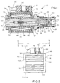
- a cartridge valve 10 includes a solenoid coil assembly 12 according to the invention for operating a valve assembly 14.
- the illustrated cartridge valve 10 comprises a normally closed pilot operated poppet type valve.
- the solenoid coil assembly 12 can be used with any cartridge type valve, as will be obvious to those skilled in the art.
- the poppet valve assembly 14 includes an adapter 16 which receives a seat member 18.
- the seat member 18 may be received in the adapter 16 in any known manner.
- the seat member 18 is provided with suitable means for being received in a fluid port, such as, for example, a drilled bore in a polyhydron or manifold.
- the seat member 18 is provided with a side opening 20 which opens radially inwardly into a valve chamber 22.
- An end opening 24 opens axially from the valve chamber 22 and is normally closed by a valve member, or poppet, 26 seating on an annular seat 28 of the seat member 18 at an inner end of the end opening 24.
- the valve member 26 comprises a poppet valve having a seating portion 30 engaging the valve seat 28 and provided with an axial bore 32 which is normally closed by a pilot valve 34 received in a cylindrical recess 36 of the valve member 26.
- the pilot valve 34 provides fluid communication between a transfer chamber 38 and a pilot valve chamber 40.
- the pilot valve 34 includes an inner end 41 secured to a solenoid armature, or plunger, 42.
- the plunger 42 is biased outwardly by a helical coil spring 44 acting between an inner end portion 46 of the plunger 42 and a plug 48.
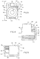
- the solenoid coil assembly 12 includes a coil sub-assembly 52, an outer shell 54, and a screw 56, see Fig. 2.
- the coil sub-assembly 52 includes a bobbin 58 having a central through opening 60 defining an axis represented by a line 62.
- a coil 64 is wound about the bobbin 58.
- the coil 64 comprises a multi-turn winding with the number of turns and size of the wire determined according to the voltage and power requirements, as is well known.
- the ends of the coil 64 are connected to electrical connectors, such as male connectors 66.
- application of power across the connectors 66 causes current flow through the coil 64 to produce a magnetic field within the bobbin through opening 60. This magnetic field acts on the plunger, or armature, 42, shown in Fig. 1 to actuate the cartridge valve 10.
- the coil sub-assembly 52 is encased in a plastic case 68.
- the case 68 in the illustrated embodiment comprises a molded plastic case which encapsulates the coil 64 and the bobbin 60.
- the case 68 includes opposite end walls 70 and 72.
- the end walls 70 and 72 are interconnected by a top wall 74 and opposite, bottom walls 76, and also by opposite and parallel side walls 78 and 80.
- the side walls 78 and 80 interconnect the top wall 74 and the bottom wall 76 to provide a generally square configuration.
- the case walls are provided with a plurality of axial ridges 82.
- the case 68 includes a connector housing 84 disposed above the top wall 74.
- the connector housing 84 is L-shaped and includes a lower portion 86 connected to the top wall 74 and having an outer wall 88 flush with the side wall 80.
- a housing upper portion 90 houses and supports the connectors 66 and is spaced outwardly from the top wall 74 to define a space 92 therebetween.
- the space 92 is laterally open from the coil assembly side wall 78 to the connector housing lower portion 86.
- An aperture 93 is provided through the top of the housing upper portion 90 for receiving the ground screw 56, see Fig. 3.
- the outer shell 54 comprises a yoke made of ferromagnetic material.
- the yoke 54 includes opposite, parallel end walls 94 and 96 connected by a top wall 98 and an opposite, parallel bottom wall 100.
- the yoke 54 may be of single piece construction, or may have separate walls which are secured together by any known means, as necessary, or desired.
- the yoke end walls 94 and 96 are generally square in the illustrated embodiment corresponding to the size of the case end walls 70 and 72, and include respective central circular openings 102 and 104.
- the openings 102 and 104 are identical in diameter and, in fact, are substantially identical in diameter to the bobbin through opening 60.
- the top wall 98 and bottom wall 100 are generally rectangular and have a length slightly greater than that of the case top and bottom walls 74 and 76, but having a narrower width. Specifically, the yoke dimensions are determined with the consideration of eliminating the need for an end wall washer, thus providing a symmetrical coil.
- the yoke bottom wall 100 is centrally positioned relative to its end walls 94 and 96, while the top wall 98 is offset from center and, in fact, has one edge flush with the side edge of the yoke end walls 94 and 96.
- the width of the top wall 98 is less than the space 92 described above between the case side wall 78 and the connector housing lower portion 86.
- the yoke 54 is mounted to the coil sub-assembly 52 by sliding it into position so that the yoke end walls 94 and 96 are in alignment with the case end walls 70 and 72 and their respective openings 102 and 104 in alignment with the bobbin central opening 60.
- the yoke top and bottom walls 98 and 100 are aligned with the case top and bottom walls 74 and 76, respectively.
- the yoke bottom wall 100 is centered relative to the case bottom wall 76.
- the yoke top wall 98 is received in the space 92 between the case top wall 74 and the enclosure housing 84.
- the yoke 54 carries the magnetic field developed in the coil 64, see Fig. 1, and is effective to increase the flux density, or magnetic induction, developed thereby.
- the structural integrity of the case is enhanced. Specifically, thermal expansion of the yoke 54 will not cause cracking of the plastic case 70. Further, since the yoke 54 does not extend beyond the case side walls 78 and 80, the valve 10 may be closely mounted to adjacent valves on either side.
- the invention broadly comprehends a solenoid coil assembly including an outer yoke which permits side-by-side installation to adjacent solenoids in close proximity.
Landscapes
- Engineering & Computer Science (AREA)
- General Engineering & Computer Science (AREA)
- Mechanical Engineering (AREA)
- Physics & Mathematics (AREA)
- Fluid Mechanics (AREA)
- Magnetically Actuated Valves (AREA)
Priority Applications (1)
| Application Number | Priority Date | Filing Date | Title |
|---|---|---|---|
| EP90312061A EP0483430A1 (fr) | 1990-11-02 | 1990-11-02 | Electrovanne |
Applications Claiming Priority (1)
| Application Number | Priority Date | Filing Date | Title |
|---|---|---|---|
| EP90312061A EP0483430A1 (fr) | 1990-11-02 | 1990-11-02 | Electrovanne |
Publications (1)
| Publication Number | Publication Date |
|---|---|
| EP0483430A1 true EP0483430A1 (fr) | 1992-05-06 |
Family
ID=8205599
Family Applications (1)
| Application Number | Title | Priority Date | Filing Date |
|---|---|---|---|
| EP90312061A Ceased EP0483430A1 (fr) | 1990-11-02 | 1990-11-02 | Electrovanne |
Country Status (1)
| Country | Link |
|---|---|
| EP (1) | EP0483430A1 (fr) |
Cited By (2)
| Publication number | Priority date | Publication date | Assignee | Title |
|---|---|---|---|---|
| WO1998038430A1 (fr) | 1997-02-27 | 1998-09-03 | Mannesmann Rexroth Ag | Soupape d'arret pilotee |
| EP1331425A1 (fr) * | 2002-01-25 | 2003-07-30 | Denso Corporation | Structure de montage d'une soupape électromagnétique |
Citations (4)
| Publication number | Priority date | Publication date | Assignee | Title |
|---|---|---|---|---|
| CH288830A (fr) * | 1950-11-09 | 1953-02-15 | Westinghouse Freins & Signaux | Electrovalve à vapeur avec dispositif de protection des organes électriques de commande dans une installation de chauffage. |
| GB1077169A (en) * | 1964-12-23 | 1967-07-26 | Thomson Houston Comp Francaise | Improvements relating to electro-magnetically actuated fluid valves |
| DE7118515U (de) * | 1971-09-02 | Sievering W U Co | Magnetventil | |
| DE2643495B2 (de) * | 1975-12-31 | 1979-10-18 | Mac Valves, Inc., Wixom, Mich. (V.St.A.) | Tauchankermagnet |
-
1990
- 1990-11-02 EP EP90312061A patent/EP0483430A1/fr not_active Ceased
Patent Citations (4)
| Publication number | Priority date | Publication date | Assignee | Title |
|---|---|---|---|---|
| DE7118515U (de) * | 1971-09-02 | Sievering W U Co | Magnetventil | |
| CH288830A (fr) * | 1950-11-09 | 1953-02-15 | Westinghouse Freins & Signaux | Electrovalve à vapeur avec dispositif de protection des organes électriques de commande dans une installation de chauffage. |
| GB1077169A (en) * | 1964-12-23 | 1967-07-26 | Thomson Houston Comp Francaise | Improvements relating to electro-magnetically actuated fluid valves |
| DE2643495B2 (de) * | 1975-12-31 | 1979-10-18 | Mac Valves, Inc., Wixom, Mich. (V.St.A.) | Tauchankermagnet |
Cited By (2)
| Publication number | Priority date | Publication date | Assignee | Title |
|---|---|---|---|---|
| WO1998038430A1 (fr) | 1997-02-27 | 1998-09-03 | Mannesmann Rexroth Ag | Soupape d'arret pilotee |
| EP1331425A1 (fr) * | 2002-01-25 | 2003-07-30 | Denso Corporation | Structure de montage d'une soupape électromagnétique |
Similar Documents
| Publication | Publication Date | Title |
|---|---|---|
| US5002253A (en) | Solenoid valve | |
| CN100523570C (zh) | 防流体电磁线圈作动阀 | |
| EP0107445B1 (fr) | Clapet électromagnétique | |
| US4564046A (en) | Solenoid valve | |
| US4067541A (en) | Water valve operating solenoid | |
| US4540154A (en) | Solenoid valve | |
| US4679767A (en) | Solenoid arrangement including yoke-enclosed coil and double encapsulation | |
| JPS61500030A (ja) | スナップ式係合弁ハウジングを備える電磁作動流体圧弁装置 | |
| US6633216B2 (en) | Self-locating coil assembly | |
| US5310160A (en) | Electromagnetic valve top part | |
| EP0790627B1 (fr) | Actionneur électromagnétique | |
| EP0175374A1 (fr) | Soupape d'inversion | |
| US5522424A (en) | Controlling the flow of fluids using solenoid-actuated valves | |
| JP4403556B2 (ja) | 電磁弁 | |
| EP2478281B1 (fr) | Vanne électromagnétique à bobines multiples | |
| US5311162A (en) | Solenoid device | |
| US4025887A (en) | AC solenoid with split housing | |
| JPH11210920A (ja) | 流体制御弁 | |
| US4286767A (en) | Solenoid actuated valve device | |
| EP0024995A1 (fr) | Actionneur électromagnétique à solénoide | |
| GB2124034A (en) | Solenoid valve | |
| US4694270A (en) | Electromagnetic proportional actuator | |
| US20060027269A1 (en) | Rapid response solenoid for electromagnetic operated valve | |
| EP0483430A1 (fr) | Electrovanne | |
| US5389910A (en) | Solenoid encasement with variable reluctance |
Legal Events
| Date | Code | Title | Description |
|---|---|---|---|
| PUAI | Public reference made under article 153(3) epc to a published international application that has entered the european phase |
Free format text: ORIGINAL CODE: 0009012 |
|
| AK | Designated contracting states |
Kind code of ref document: A1 Designated state(s): DE FR GB |
|
| 17P | Request for examination filed |
Effective date: 19920522 |
|
| 17Q | First examination report despatched |
Effective date: 19940303 |
|
| STAA | Information on the status of an ep patent application or granted ep patent |
Free format text: STATUS: THE APPLICATION HAS BEEN REFUSED |
|
| 18R | Application refused |
Effective date: 19951217 |