EP0483457A1 - Dispositif pour réduire le délai d'allumage d'un moteur diesel à injection indirecte - Google Patents
Dispositif pour réduire le délai d'allumage d'un moteur diesel à injection indirecte Download PDFInfo
- Publication number
- EP0483457A1 EP0483457A1 EP91110918A EP91110918A EP0483457A1 EP 0483457 A1 EP0483457 A1 EP 0483457A1 EP 91110918 A EP91110918 A EP 91110918A EP 91110918 A EP91110918 A EP 91110918A EP 0483457 A1 EP0483457 A1 EP 0483457A1
- Authority
- EP
- European Patent Office
- Prior art keywords
- combustion chamber
- shutter
- duct
- engine
- thrust
- Prior art date
- Legal status (The legal status is an assumption and is not a legal conclusion. Google has not performed a legal analysis and makes no representation as to the accuracy of the status listed.)
- Withdrawn
Links
- 208000015181 infectious disease Diseases 0.000 title 1
- 238000002485 combustion reaction Methods 0.000 claims abstract description 60
- 239000012530 fluid Substances 0.000 claims abstract description 3
- 238000004904 shortening Methods 0.000 claims abstract 2
- 239000000446 fuel Substances 0.000 description 12
- 238000002347 injection Methods 0.000 description 7
- 239000007924 injection Substances 0.000 description 7
- 230000006835 compression Effects 0.000 description 6
- 238000007906 compression Methods 0.000 description 6
- 239000000203 mixture Substances 0.000 description 3
- 238000012986 modification Methods 0.000 description 3
- 230000004048 modification Effects 0.000 description 3
- 239000002283 diesel fuel Substances 0.000 description 2
- 238000000889 atomisation Methods 0.000 description 1
- 239000011324 bead Substances 0.000 description 1
- 230000015572 biosynthetic process Effects 0.000 description 1
- 230000003247 decreasing effect Effects 0.000 description 1
- 230000007717 exclusion Effects 0.000 description 1
- 238000004880 explosion Methods 0.000 description 1
- 239000003517 fume Substances 0.000 description 1
- 238000004519 manufacturing process Methods 0.000 description 1
- 230000000284 resting effect Effects 0.000 description 1
- 238000007789 sealing Methods 0.000 description 1
- 239000007921 spray Substances 0.000 description 1
Images
Classifications
-
- F—MECHANICAL ENGINEERING; LIGHTING; HEATING; WEAPONS; BLASTING
- F02—COMBUSTION ENGINES; HOT-GAS OR COMBUSTION-PRODUCT ENGINE PLANTS
- F02B—INTERNAL-COMBUSTION PISTON ENGINES; COMBUSTION ENGINES IN GENERAL
- F02B19/00—Engines characterised by precombustion chambers
- F02B19/02—Engines characterised by precombustion chambers the chamber being periodically isolated from its cylinder
-
- F—MECHANICAL ENGINEERING; LIGHTING; HEATING; WEAPONS; BLASTING
- F02—COMBUSTION ENGINES; HOT-GAS OR COMBUSTION-PRODUCT ENGINE PLANTS
- F02B—INTERNAL-COMBUSTION PISTON ENGINES; COMBUSTION ENGINES IN GENERAL
- F02B3/00—Engines characterised by air compression and subsequent fuel addition
- F02B3/06—Engines characterised by air compression and subsequent fuel addition with compression ignition
-
- Y—GENERAL TAGGING OF NEW TECHNOLOGICAL DEVELOPMENTS; GENERAL TAGGING OF CROSS-SECTIONAL TECHNOLOGIES SPANNING OVER SEVERAL SECTIONS OF THE IPC; TECHNICAL SUBJECTS COVERED BY FORMER USPC CROSS-REFERENCE ART COLLECTIONS [XRACs] AND DIGESTS
- Y02—TECHNOLOGIES OR APPLICATIONS FOR MITIGATION OR ADAPTATION AGAINST CLIMATE CHANGE
- Y02T—CLIMATE CHANGE MITIGATION TECHNOLOGIES RELATED TO TRANSPORTATION
- Y02T10/00—Road transport of goods or passengers
- Y02T10/10—Internal combustion engine [ICE] based vehicles
- Y02T10/12—Improving ICE efficiencies
Definitions
- the invention discloses a device to shorten the ignition delay of a diesel engine with indirect ignition.
- a device which, by acting simultaneously on both the temperature of the comburant air and on the turbulence of the fuel mixture, makes it possible to considerably shorten the ignition delay in an indirect diesel engine.
- a device meant to shorten the ignition delay in an indirect diesel engine, comprising:
- the shutter consists of a cylinder presenting a tapered end, which acts as a seal when resting against a corresponding seat having the shape of a truncated cone which is present in the supply duct and which connects the pre-combustion chamber with the combustion chamber.
- the shutter slides within a seat having a labyrinth seal obtained within the engine cylinder head and it is pushed from its rear by a spring which can be calibrated.
- a counter-pressure hydraulic system consisting of a tank containing oil under pressure and by ducts for the connection with the shutter seat, prevents sudden return movements of the shutter against sealing seat having the shape of a truncated cone during its closing phase.
- the device according to the invention permits the decrease of the running roughness of the engine and also its improved efficiency.
- the shutter intercepts the supply duct which connects the combustion chamber with the pre-combustion chamber, so that, during the compression phase, the pre-combustion chamber is shut off.
- the shutter opens the duct and air streams into the pre-combustion chamber with a strong vorticosity and its temperature is the one that has been reached at the top dead center and is, therefore, ideal for the ignition of the diesel fuel.
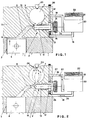
- the device according to the invention which is indicated as a whole with 1, is applied to an indirect diesel engine consisting of a block 2, housing cylinder 3 within which piston 4 slides, and of a cylinder head 5, within which a pre-combustion chamber 7 is obtained, which is connected with a combustion chamber 6 through a supply duct 8.
- the supply duct 8 presents in its intermediate position a seat 9 in the shape of a truncated cone, suited to lodge the tapered end 10 of a shutter 11 sliding within a housing 12 with a labyrinth seal 13, preferably obtained within the cylinder bead 5.
- the tapered end 10 of shutter 11 is closed against the corresponding seat 9 in the sahpe of a truncated cone, since it is pushed against said seat by the pressure of a spring 14 positioned at the rear end 16.
- This spring can be calibrated by means of the threaded closing lid 15.
- Said end 16 creates within the housing 12, within which the shutter slides, an annular chamber 17 which, through an upper duct 18 and a lower duct 19 is connected with a tank 20 containing oil.
- Said oil is kept under a slight pressure by the presence of piston 21 on which a spring 22 exerts through it and directly on the oil an amount of pressure corresponding with the degree of compression of spring 22.
- This strong turbulence is generated not only by the shape of the pre-combustion chamber, but also particularly by the sudden opening of shutter 11, and it is far stronger than the turbulence generated in compression engines with indirect ignition, wherein the pressure increase within the pre-combustion chamber 7 occurs gradually during the entire upward stroke of piston 4. At this point injector 23 begins its operation.
- the flow 28 through duct 18 stops when the tapered end 10 of shutter 11 is again flush against its seat 9 having the shape of a truncated cone.
- the device according to the invention fulfils the proposed purposes. It has been seen how, through shutter 11 and the adequate calibration of spring 14 which pushes it against its seat 9 having the shape of a truncated cone and being positioned within each supply duct 8, it is possible to obtain near the top dead center the sudden connection between the combustion chamber 6 and the pre-combustion chamber 7, thereby causing at the interior of the latter a strong swirling movement of the compressed air, which also presents the temperature conditions which are ideal to receive the atomized diesel oil and to cause its ignition. This makes it possible to shorten the ignition delay and, as a consequence, also the injection advance to the advantage of a less rough running and of an improved efficiency of the engine.
Landscapes
- Engineering & Computer Science (AREA)
- Chemical & Material Sciences (AREA)
- Combustion & Propulsion (AREA)
- Mechanical Engineering (AREA)
- General Engineering & Computer Science (AREA)
- Combustion Methods Of Internal-Combustion Engines (AREA)
- Ignition Installations For Internal Combustion Engines (AREA)
- Electrical Control Of Ignition Timing (AREA)
Applications Claiming Priority (2)
| Application Number | Priority Date | Filing Date | Title |
|---|---|---|---|
| IT8563390 | 1990-10-31 | ||
| IT08563390A IT1243155B (it) | 1990-10-31 | 1990-10-31 | Dispositivo di riduzione del ritardo di accensione in un motore diesel ad accensione indiretta |
Publications (1)
| Publication Number | Publication Date |
|---|---|
| EP0483457A1 true EP0483457A1 (fr) | 1992-05-06 |
Family
ID=11329328
Family Applications (1)
| Application Number | Title | Priority Date | Filing Date |
|---|---|---|---|
| EP91110918A Withdrawn EP0483457A1 (fr) | 1990-10-31 | 1991-07-02 | Dispositif pour réduire le délai d'allumage d'un moteur diesel à injection indirecte |
Country Status (3)
| Country | Link |
|---|---|
| EP (1) | EP0483457A1 (fr) |
| JP (1) | JPH04265421A (fr) |
| IT (1) | IT1243155B (fr) |
Cited By (1)
| Publication number | Priority date | Publication date | Assignee | Title |
|---|---|---|---|---|
| FR2980239A1 (fr) * | 2011-09-16 | 2013-03-22 | Michel Pierre Marie Toulminet | Moteur thermique a preinjection et a vaporisation pour tous combustibles, a cylindree operationnelle variable, a recuperation d'energie cinetique, a stockage et a reutilisation pneumatique et electrique |
Families Citing this family (3)
| Publication number | Priority date | Publication date | Assignee | Title |
|---|---|---|---|---|
| US20020134345A1 (en) * | 2001-03-20 | 2002-09-26 | Adams Joseph S. | Combustion chamber system |
| JP5636885B2 (ja) | 2010-11-08 | 2014-12-10 | 株式会社リコー | 画像処理装置、画像形成装置、及び画像処理システム |
| JP5879140B2 (ja) | 2012-02-03 | 2016-03-08 | 株式会社Screenホールディングス | 印刷画像検査装置及び印刷画像検査方法 |
Citations (4)
| Publication number | Priority date | Publication date | Assignee | Title |
|---|---|---|---|---|
| BE364612A (fr) * | ||||
| NL81021C (fr) * | ||||
| FR2342399A1 (fr) * | 1976-02-24 | 1977-09-23 | Chrysler France | Perfectionnements a un moteur a combustion interne du type diesel |
| US4846125A (en) * | 1986-10-24 | 1989-07-11 | Kabushiki Kaisha Hareyama Giken | Internal combustion engine |
Family Cites Families (1)
| Publication number | Priority date | Publication date | Assignee | Title |
|---|---|---|---|---|
| JPS56110031A (en) * | 1980-02-05 | 1981-09-01 | Nippon Telegr & Teleph Corp <Ntt> | Measuring device for tension of cable |
-
1990
- 1990-10-31 IT IT08563390A patent/IT1243155B/it active IP Right Grant
-
1991
- 1991-07-02 EP EP91110918A patent/EP0483457A1/fr not_active Withdrawn
- 1991-10-31 JP JP3286865A patent/JPH04265421A/ja active Pending
Patent Citations (4)
| Publication number | Priority date | Publication date | Assignee | Title |
|---|---|---|---|---|
| BE364612A (fr) * | ||||
| NL81021C (fr) * | ||||
| FR2342399A1 (fr) * | 1976-02-24 | 1977-09-23 | Chrysler France | Perfectionnements a un moteur a combustion interne du type diesel |
| US4846125A (en) * | 1986-10-24 | 1989-07-11 | Kabushiki Kaisha Hareyama Giken | Internal combustion engine |
Cited By (1)
| Publication number | Priority date | Publication date | Assignee | Title |
|---|---|---|---|---|
| FR2980239A1 (fr) * | 2011-09-16 | 2013-03-22 | Michel Pierre Marie Toulminet | Moteur thermique a preinjection et a vaporisation pour tous combustibles, a cylindree operationnelle variable, a recuperation d'energie cinetique, a stockage et a reutilisation pneumatique et electrique |
Also Published As
| Publication number | Publication date |
|---|---|
| JPH04265421A (ja) | 1992-09-21 |
| IT1243155B (it) | 1994-05-24 |
| IT9085633A0 (it) | 1990-10-31 |
| IT9085633A1 (it) | 1992-05-01 |
Similar Documents
| Publication | Publication Date | Title |
|---|---|---|
| US5261366A (en) | Method of fuel injection rate control | |
| US4499862A (en) | Injection device for direct injection diesel engines using alcohol and diesel fuel | |
| US4807572A (en) | Timing of fuel injected engines | |
| US5887566A (en) | Gas engine with electronically controlled ignition oil injection | |
| US5353992A (en) | Multi-hole injector nozzle tip with low hydraulic plume penetration and large cloud-forming properties | |
| JP2645577B2 (ja) | 電子ユニットインジェクタ | |
| US4867115A (en) | Cranking fuel control method and apparatus for combustion engines | |
| US4781164A (en) | Fuel injection systems for internal combustion engines | |
| AU720617B2 (en) | The invention relates to a method of operating an internal combustion engine and to an internal combustion engine | |
| JP2000027740A (ja) | 圧縮空気を補助とした排気駆動制御式燃料噴射システム | |
| RU2721745C2 (ru) | Способ регулирования параметра работы двигателя (варианты) и соответствующая система | |
| DE69310674T2 (de) | Steuereinheit für hochverdichtende Motoren unter Verwendung von verdampfenden Kraftstoffen | |
| US4334514A (en) | Fuel injection pump for internal combustion engine | |
| EP0483457A1 (fr) | Dispositif pour réduire le délai d'allumage d'un moteur diesel à injection indirecte | |
| NZ335482A (en) | Process for the formation of a fuel mixture and for its ignition in a pre-chamber that is open toward the cylinders | |
| US4733645A (en) | Fuel injection pump for internal combustion engines | |
| US4549511A (en) | Fuel injection system for direct fuel injection in internal combustion engines | |
| US2986134A (en) | Combination fuel pump and fuel injector apparatus | |
| JP2004521248A (ja) | 内燃機関に用いられる燃料噴射装置 | |
| US7124734B2 (en) | Method of reducing exhaust gas emissions during cold start conditions and an internal combustion engine in which the method is used | |
| US5381772A (en) | Liquid fuel injection device for an internal combustion engine, and engine equipped with such a device | |
| GB2097471A (en) | I.C. engine fuel injection nozzle | |
| US4165838A (en) | Fuel injection nozzle | |
| US20040020458A1 (en) | Method for operating a pump-nozzle unit and a corresponding pump-nozzle unit | |
| DE3148215A1 (de) | Kraftstoffeinspritzpumpe fuer brennkraftmaschinen |
Legal Events
| Date | Code | Title | Description |
|---|---|---|---|
| PUAI | Public reference made under article 153(3) epc to a published international application that has entered the european phase |
Free format text: ORIGINAL CODE: 0009012 |
|
| AK | Designated contracting states |
Kind code of ref document: A1 Designated state(s): AT BE CH DE ES FR GB IT LI NL SE |
|
| 17P | Request for examination filed |
Effective date: 19920708 |
|
| 17Q | First examination report despatched |
Effective date: 19920916 |
|
| STAA | Information on the status of an ep patent application or granted ep patent |
Free format text: STATUS: THE APPLICATION HAS BEEN WITHDRAWN |
|
| 18W | Application withdrawn |
Withdrawal date: 19921021 |