EP0483621B1 - Heizvorrichtung, speziell in Form eines Bandes oder Streifens - Google Patents
Heizvorrichtung, speziell in Form eines Bandes oder Streifens Download PDFInfo
- Publication number
- EP0483621B1 EP0483621B1 EP91117843A EP91117843A EP0483621B1 EP 0483621 B1 EP0483621 B1 EP 0483621B1 EP 91117843 A EP91117843 A EP 91117843A EP 91117843 A EP91117843 A EP 91117843A EP 0483621 B1 EP0483621 B1 EP 0483621B1
- Authority
- EP
- European Patent Office
- Prior art keywords
- heating element
- end portions
- heater
- heater assembly
- dielectric
- Prior art date
- Legal status (The legal status is an assumption and is not a legal conclusion. Google has not performed a legal analysis and makes no representation as to the accuracy of the status listed.)
- Expired - Lifetime
Links
- 238000010438 heat treatment Methods 0.000 claims description 39
- 239000000463 material Substances 0.000 claims description 10
- 238000000034 method Methods 0.000 claims description 8
- 238000010292 electrical insulation Methods 0.000 claims description 6
- 239000012774 insulation material Substances 0.000 claims description 6
- 239000010445 mica Substances 0.000 claims description 6
- 229910052618 mica group Inorganic materials 0.000 claims description 6
- 238000003466 welding Methods 0.000 claims description 6
- 239000002245 particle Substances 0.000 claims description 5
- 230000002093 peripheral effect Effects 0.000 claims description 5
- 230000008569 process Effects 0.000 claims description 4
- 239000011230 binding agent Substances 0.000 claims description 3
- 239000000919 ceramic Substances 0.000 claims description 3
- 230000004927 fusion Effects 0.000 claims description 2
- 239000003989 dielectric material Substances 0.000 claims 2
- 239000012212 insulator Substances 0.000 description 42
- 238000010276 construction Methods 0.000 description 40
- 239000011810 insulating material Substances 0.000 description 5
- 229910052751 metal Inorganic materials 0.000 description 5
- 239000002184 metal Substances 0.000 description 5
- WABPQHHGFIMREM-UHFFFAOYSA-N lead(0) Chemical compound [Pb] WABPQHHGFIMREM-UHFFFAOYSA-N 0.000 description 4
- 238000004519 manufacturing process Methods 0.000 description 4
- 229910000680 Aluminized steel Inorganic materials 0.000 description 3
- 229910010293 ceramic material Inorganic materials 0.000 description 3
- 238000009434 installation Methods 0.000 description 3
- 238000004804 winding Methods 0.000 description 3
- VYPSYNLAJGMNEJ-UHFFFAOYSA-N Silicium dioxide Chemical compound O=[Si]=O VYPSYNLAJGMNEJ-UHFFFAOYSA-N 0.000 description 2
- 238000002788 crimping Methods 0.000 description 2
- 238000009826 distribution Methods 0.000 description 2
- 238000009413 insulation Methods 0.000 description 2
- 230000007246 mechanism Effects 0.000 description 2
- 239000007769 metal material Substances 0.000 description 2
- 230000002028 premature Effects 0.000 description 2
- 229910052582 BN Inorganic materials 0.000 description 1
- PZNSFCLAULLKQX-UHFFFAOYSA-N Boron nitride Chemical compound N#B PZNSFCLAULLKQX-UHFFFAOYSA-N 0.000 description 1
- HCHKCACWOHOZIP-UHFFFAOYSA-N Zinc Chemical compound [Zn] HCHKCACWOHOZIP-UHFFFAOYSA-N 0.000 description 1
- 230000006978 adaptation Effects 0.000 description 1
- 230000003466 anti-cipated effect Effects 0.000 description 1
- 239000011324 bead Substances 0.000 description 1
- 239000007795 chemical reaction product Substances 0.000 description 1
- 238000005336 cracking Methods 0.000 description 1
- 230000007423 decrease Effects 0.000 description 1
- 230000002452 interceptive effect Effects 0.000 description 1
- 239000000395 magnesium oxide Substances 0.000 description 1
- CPLXHLVBOLITMK-UHFFFAOYSA-N magnesium oxide Inorganic materials [Mg]=O CPLXHLVBOLITMK-UHFFFAOYSA-N 0.000 description 1
- AXZKOIWUVFPNLO-UHFFFAOYSA-N magnesium;oxygen(2-) Chemical compound [O-2].[Mg+2] AXZKOIWUVFPNLO-UHFFFAOYSA-N 0.000 description 1
- 230000013011 mating Effects 0.000 description 1
- 150000002739 metals Chemical class 0.000 description 1
- 239000000203 mixture Substances 0.000 description 1
- 230000004048 modification Effects 0.000 description 1
- 238000012986 modification Methods 0.000 description 1
- 229910001120 nichrome Inorganic materials 0.000 description 1
- TWNQGVIAIRXVLR-UHFFFAOYSA-N oxo(oxoalumanyloxy)alumane Chemical compound O=[Al]O[Al]=O TWNQGVIAIRXVLR-UHFFFAOYSA-N 0.000 description 1
- 230000001681 protective effect Effects 0.000 description 1
- 238000002310 reflectometry Methods 0.000 description 1
- 239000000377 silicon dioxide Substances 0.000 description 1
- 235000012239 silicon dioxide Nutrition 0.000 description 1
- 229910052725 zinc Inorganic materials 0.000 description 1
- 239000011701 zinc Substances 0.000 description 1
Images
Classifications
-
- H—ELECTRICITY
- H05—ELECTRIC TECHNIQUES NOT OTHERWISE PROVIDED FOR
- H05B—ELECTRIC HEATING; ELECTRIC LIGHT SOURCES NOT OTHERWISE PROVIDED FOR; CIRCUIT ARRANGEMENTS FOR ELECTRIC LIGHT SOURCES, IN GENERAL
- H05B3/00—Ohmic-resistance heating
- H05B3/40—Heating elements having the shape of rods or tubes
- H05B3/54—Heating elements having the shape of rods or tubes flexible
- H05B3/58—Heating hoses; Heating collars
Definitions
- the invention relates to a heater assembly in the form of a band or strip according to the preamble of claim 1.
- Band and strip heaters are typically custom fabricated in accordance with the particular specifications of the end user. Besides specifying the particular performance characteristics and operating factors desired in a particular heater unit, such as voltage, wattage, power supply, dimensional and other special requirements, the end user also specifies the particular lead or terminal configuration necessary for adaptation of the heater to the particular application in question.
- lead and/or terminal configurations are available and adaptable for use with band and strip type heaters and such configurations may vary considerably from one application to another. Typical of the known band and strip heater constructions including lead and/or terminal connections associated therewith are those shown and disclosed in U.S. - A - 4,203,197; 3,872,281; and 3,889,362.
- the present invention improves the performance and reliability of band and strip type heaters by eliminating the need to crimp or stake the terminal connection end portions of the heating element to the insulation material or any other component of such heater. Further, the invention teaches the construction and operation of several embodiments of a lead/terminal connection member which will facilitate the adaption and joinder of a wide variety of lead and terminal configurations to the present heater construction, the construction and operation of a heater construction which will enable manufacturers of band and strip type heaters to reduce their stock inventory yet still offer their customers a broad selection of such heaters including a broad selection of lead/terminal configurations associated therewith, the construction and operation of a heater construction which will reduce and improve the time needed to deliver such heaters to the end user, the construction and operation of a heater construction wherein all of the electrical connections associated with such heater are welded connections and the construction and operation of a heater construction having clamping means associated therewith which not only provides for a more uniform load distribution over the heating element housed therein but also simplifies the installation of such heater by eliminating the need to align strap
- the invention provides a heater construction that is structurally and operationally relatively simple to make, a band heater construction which can be more easily expanded to fit around the particular cylindrical surface to be heated without detrimentally affecting or otherwise interfering with or hindering the overall performance and reliability of such unit, and a more responsive and reliable heater and one which is not easily susceptible to premature heater failure, erratic, or less than fully dependably performance.
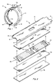
- Figs. 1 and 2 show one embodiment of a basic band or strip heater assembly 10 being manufactured and assembled without termination and attachment means associated therewith.
- the heater assembly 10 includes a channel-shaped upper sheath or cover member 12 having a pair of downwardly extending opposed side wall portions 14 associated therewith.
- the channel-shaped member 12 is generally made of a metallic material and further includes a tab member 16 associated with each respective opposite end portion thereof as well as an elongated slot or opening 18 positioned at an intermediate location therebetween.
- the heating element 20 is a conventional bifiler winder construction which includes a pair of electrical resistance wires 22 and 24 helically wrapped or wound in parallel relationship around a sheet of insulator material 26.
- the bifiler wound construction is achieved by first winding the resistance wires 22 and 24 in parallel around the insulator strip 26 from one end to the other in accordance with known techniques and thereafter welding together the respective opposite ends thereof so as to create a closed loop therebetween. This joined wire arrangement is then severed at a predetermined intermediate location as desired thereby forming an electrical circuit having terminal end portions 28 and 30 as shown in Figs. 1 and 2.
- the resistance wires 22 and 24 are generally formed of a ribbon of nichrome wire, although any suitable high temperature electrical resistance means can be utilized.
- the terminal wire end portions 28 and 30 are each preferably doubled over and welded respectively to themselves so as to form a double layer construction at end portions 28 and 30. This lowers the resistance of the wire end portions 28 and 30 and allows such end portions to operate at cooler temperatures at the point of connection to a particular lead/terminal arrangement.
- the heating element 20 is sandwiched between two strips or sheets of insulation material 32 and 34 which effectively insulate the heating element 20 from the metallic heat conducting parts 12 and 36 as will be hereinafter explained.
- the upper insulator sheet 34 likewise includes an elongated slot 38 positioned thereon so as to receive the terminal end portions 28 and 30 of the heating element 20 when positioned in overlaying relationship thereto. Slot 38 is also located so as to lie in registration with slot 18 associated with the cover member 12.
- Insulator sheets 26, 32 and 34 are typically comprised of either mica or high density ceramic particles bound together by a suitable binder, or any other suitable insulating material.
- the ceramic particles typically include particles of aluminum oxide, magnesium oxide, boron nitride, or silicon dioxide.
- a bottom cover plate 36 completes the components of the basic heater unit 10.
- the plate member 36 is likewise generally made of a metallic material and is dimensioned so as to be received within the channel-shaped cover member 12.
- the sandwich sub-assembly or heater core body comprising heating element 20 and insulator sheets 32 and 34 is placed within the channel-shaped cover member 12 such that the heating element terminal end portions 28 and 30 extend through slot means 38 and 18 and are readily exposed exterior of the member 12.
- Plate member 36 is now positioned within the channel-shaped member 12 in abutment with the insulator sheet 32.
- the plate member 36 and the insulator sheets 32 and 34 are of about the same length and width as the channel-shaped cover member 12 so as to fit snugly therewithin.
- the insulator sheet 26 associated with the heating element 20, while about the same length as the cover member 12, is preferably somewhat narrower than insulator strips 32 and 34 so as to provide a small gap 39 (Fig. 3) for electrical clearance between the resistance means 22 and 24 and the channel side portions 14.
- the channel side portions 14 are folded tightly inwardly over plate member 36 to close the assembly as shown in Fig. 3.
- the members 12 and 36 thereby form a sheath totally enclosing and encasing the internal components of the heater.
- the closed assembly is then rolled flat or is formed into a curved finished shape in accordance with known procedures.
- the assembly may be shaped, for example, into the configuration of a curved band heater as shown in Fig.
- the assembly may be left in its extended form so as to be completed as a strip heater (not shown).
- the assembly is normally fired at an elevated temperature sufficient to vaporize and bake out the binder materials associated with the insulator sheets 26, 32 and 34.
- the sheath members 12 and 36 are typically constructed of selected metals to provide high reflectivity, high emissivity and good conductive characteristics to efficiently transmit heat from the core element 20 towards the plate member 36 which lies adjacent to the particular object or surface to be heated.
- the channel-shaped cover member 12 is typically made of aluminized steel which has a highly reflective surface thereby directing the heat from the heater element 20 back towards the part or surface to be heated.
- the plate member 36 is typically made of a zinc coated metal which has good emissivity. This increases the heat transfer rate through this relatively thin layer of metal to the part or surface to be heated.
- the thickness of the Insulation material positioned between the outer sheath member 12 and the heating element 20 can be made greater as compared to the thickness of insulation sheet 32 so as to further direct the heat generated by the heater element 20 towards the plate member 36.
- the insulator strips 26, 32 and 34 can be comprised of different material compositions to further enhance the heat transfer capabilities of the unit. All of these various combinations contribute to the overall efficiency of the heater.
- the terminal end portions 28 and 30 of the heater element 20 are readily exposed exterior of the upper cover member 12 for easy access and later connection to any one of a plurality of lead/terminal configurations as will be hereinafter explained.
- the heater construction 10 can be fully manufactured and stocked in such manner. Once an end user specifies a particular lead/terminal arrangement, such heaters can then be easily and quickly equipped to fill such order. This is extremely advantageous for all of the reasons previously explained.
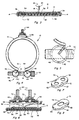
- Figs. 4 and 5 illustrate the construction and design of an improved clamping means 40 particularly adaptable for use on a band type heater such as the basic band heater construction 10 illustrated in Fig. 1.
- clamp or attachment means 40 includes a pair of clamp bar members 42 and 44 each having an elongated slot 46 extending the full length thereof.
- the members 42 and 44 are each respectively attached to the outer cover member 12 through use of the tab members 16, each slot 46 being dimensioned so as to insertably receive the tab 16 as best shown in Fig. 5. Once the tab members 16 are engaged with the bar members 42 and 44, such members are then attached to each other by a staking or crimping process as illustrated in Fig. 5.
- Each bar member 42 and 44 likewise includes an opening 48 extending transversely therethrough at an intermediate location therealong, each such opening 48 being in registration with each other and at least one of such openings 48 being adaptable to threadably receive a threaded fastening member such as the member 50 (Fig. 4). Threading the fastener member 50 through at least one threaded bore 48 such as the threaded bore 48 extending through the bar member 42 (Fig. 5) will draw the respective terminal end portions 52 and 54 of the heater 10 towards each other thereby securely fastening and clamping the heater 10 around the cylindrical object over which it is positioned. Although only the opening 48 extending through bar member 42 (Figs.
- the opening 48 extending through bar member 44 may likewise be threaded if so desired.
- the tab members 16 carry and distribute the load over the entire unit by means of the outer sheath member 12, thus eliminating the use of straps and other clamping mechanisms. This provides a more uniform load distribution over the internally housed heating element 20 and draws the heater tightly and evenly to the cylindrical surface to which it is attached. This assures a critical mating of the heater surface to the cylindrical surface to which it is attached thereby eliminating air gaps that can cause early failures.
- each bar member 42 and 44 may include any plurality of openings 48 spaced along the length thereof, each such opening on bar member 42 being in registration with a corresponding opening positioned on bar member 44 and each such respective pairs of openings 48 being adaptable to receive a threaded fastening member as previously described.
- This will provide sufficient clamping means to securely and evenly fasten wider heater units around the surface over which they are positioned along their entire width.
- the clamp mechanism 40 also simplifies the installation of such heaters by eliminating the need to align straps and terminals commonly associated with other clamping means.
- Figs. 6 and 7 illustrate one embodiment of a specially adapted add-on terminal connection member 56 specifically adaptable for use when the termination option calls for a post terminal arrangement.
- the terminal connection or cap member 56 is somewhat oval in shape and includes a pair of openings 58 extending therethrough as best shown in Fig. 7.
- the cap member 56 is formed of an aluminized steel material and likewise includes a downwardly extending peripheral flange or skirt portion 60 having a pair of triangularly-shaped weld projections or dimples 62 located respectively on at least two opposite sides thereof as best illustrated in Fig. 7.
- a pair of post terminals 64 each having a flanged bead portion 65 associated respectively therewith are insertably positioned through the openings 58 of the cap member 56 in such a way that both the terminals and the cap member are electrically isolated. This is accomplished by positioning a pair of insulator members 66 and 68 between the flanged head portions 65 of the post terminals 64 and the inside portion of the cap member 56 as shown in Fig. 6.
- Each of the insulator members 66 and 68 is preferably oval in shape so as to fit within the formed flange portion of the cap member 56 and each includes a pair of openings extending therethrough adapted to receive the post terminals 64 when inserted therethrough.
- the openings associated with insulator members 66 and 68 are positioned and located thereon so as to be in registration with the openings 58 associated with the cap member 56. Once the post terminals 64 are shielded by the insulator members 66 and 68 and are thereafter inserted through the openings 58 as shown in Fig. 6, such terminals are held in engagement with the cap member 56 through use of the locking nut members 7C or other suitable locking means. To further insulate the post terminals 64 from the upper surface portion of the cap member 56, any number of suitable insulating washers may be positioned therebetween such as the respective pairs of washers 72 illustrated in Fig. 6.
- insulator members 66, 68 and 72 are disclosed and described with respect to the post terminal configuation illustrated in Fig. 6, it is recognized that a wide variety of other suitable means may likewise be utilized to electrically insulate the terminals 64 from the cap member 56.
- the post terminal option illustrated in Fig. 6 is fully assembled prior to connection to the basic heater unit 10.
- the heating element end portions 28 and 30 are inserted through a slotted insulator member 74 so as to insulate the same from the outer cover member 12 as illustrated in Fig. 6.
- the insulator member 74 should be shaped and dimensioned so as to preferably completely cover the slot means 18.
- each of the insulator members 66, 68, 72 and 74 is preferably made of a ceramic material or mica, although other suitable insulating materials may likewise be utilized.
- the heater element end portions 28 and 30 can now each be welded respectively to the bottom of one of the flanged head portions 65 of the post terminals 64 using a special welding technique.
- the terminal cap member 56 is then welded to the outer metal sheath member 12 through use of the weld projections or dimples 62.
- This weld is made with one operating cycle of a suitable welding machine. More particularly, the welder current is concentrated at the various projections 62 thus causing each projection to melt, thereby creating a fusion bond with the cover member 12. This welding process permanently attaches the terminal cap member 56 to the outer sheath member 12.
- the terminal cap member 56 provides a base to rigidly hold the post terminals 64 and, once such member is installed on the basic heater unit 10, it gives electrical protection to the welded connection between the resistance wires 28 and 30 and the post terminals 64. Also, importantly, the cap member 56 enables increased torque to be applied to the post terminal connection. This allows all of the torque carrying capability to be maintained within the cap design independent of its electrical connection to the basic heater unit. Also, the post terminal hardware 64 and 70 can be torqued to a specific setting and tested prior to connection to the actual heater. This greatly improves the reliability and performance of the overall heater. Also, since the heater element end portions 28 and 30 are welded to the post terminals 64, all electrical connections within the heater assembly are welded connections. This obviates the need to utilize other electrical connection means such as crimping or staking the heater element end portions to other components associated with the heater. This greatly improves the performance and reliability of such heaters and helps to eliminate premature heater failure.
- Figs. 8 and 9 illustrate another embodiment of a specially adapted add-on lead connection member 76 specifically adaptable for use when the termination option calls for any one of a plurality of various lead termination arrangements.
- the lead connection or cap member 76 is substantially identical in shape and construction as cap member 56 except that the member 76 includes only a single opening 78 extending therethrough as best shown in Fig. 9.
- the opening 78 is of sufficient size and shape to accept the various known lead wire arrangements including lead wires housed in various conduit and sleeving devices.
- the lead cap member 76 can be made and stocked with various sized openings 78 depending upon the particular diameter or other shape associated with the lead configuration selected.
- the lead cap member 76 is likewise formed of an aluminized steel material and includes a peripheral flange or skirt portion 80 having similarly located triangularly-shaped weld projections or dimples 82 associated therewith as best illustrated in Fig. 9.
- the lead assembly arrangement illustrated in Fig. 8 includes a generally cylindrically-shaped eyelet member 84 having a flanged lower portion 86 associated therewith, the eyelet member 84 being insertably positioned through the opening 78 as illustrated.
- the lower flange portions 86 are welded to the inside portion of the lead cap member 76 and a suitably dimensioned insulator member such as the member 88 is positioned thereover within the formed flange portion of the cap member 76 as illustrated in Fig. 8.
- the insulator member 88 includes an opening 90 of approximately the same dimension as the opening through the eyelet member 84 and functions to insulate the end portions of the lead termination wires from the inside portion of the cap member 76.
- the opening 90 associated with the insulator member 88 is positioned and located so as to be in registration with the opening associated with the eyelet member 84.
- the appropriate lead wire arrangement is now inserted through the insulator member 88 and the eyelet member 84.
- the lead wires are encased in a protective sleeving member 92 and the respective stranded wire end portions 94 and 96 are suitably flattened for joinder to the heating element end portions 28 and 30 as will be hereinafter described.
- the wire end portions 28 and 30 are thereafter inserted through a slotted insulator member 98 similar to the insulator member 74 (Fig. 6), which insulator member 98 is positioned over the outer sheath member 12 (Fig.
- the heating element end portions 28 and 30 are then suitably welded to the flattened lead wire end portions 94 and 96 to complete the electrical connection therebetween.
- the lead cap member 76 is thereafter projection welded to the outer cover member 12 as previously described and the eyelet member 84 is suitably crimped about the sleeving member 92 adjacent its upper end portion 100 so as to provide suitable strain relief to the welded electrical connection.
- the insulator members 88 and 98 illustrated in Fig. 8 are likewise made of a suitable insulating material such as a ceramic material or mica as previously described.
- a suitable insulating material such as a ceramic material or mica
- lead termination construction and arrangement is illustrated in Fig. 6, such configuration is likewise generally adaptable for use with most of the lead wire termination options available.
- a wide variety of other suitable insulator and eyelet constructions and arrangements may likewise be utilized in conjunction with the lead cap member 76 (Figs. 8 and 9). Nevertheless, regardless of the particular component structure and arrangement, lead cap member 76 fulfills all of the objectives and advantages previously described with respect to cap member 56.
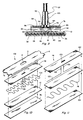
- Figs. 10 and 11 illustrate the other embodiment of the heater assembly constructed according to the preamble of Claim 1. More particularly, Fig. 10 identifies embodiment 102 which illustrates the use of a sinuated wire element construction in conjunction with the present heater assembly. As shown, a pair of sinuated wires 104 having terminal end portions 106 and 108 are sandwiched between a pair of insulator members 110 and 112.
- the upper insulator member 112 like the insulator member 34 (Fig. 2), also includes an elongated slot 114 positioned thereon so as to receive therethrough the heating element end portions 106 and 108 when the member 112 is positioned in overlaying relationship thereto as illustrated in Fig. 10.
- the heating element 104 is not wrapped or wound about a sheet or strip of insulator material. Instead, embodiment 102 utilizes only two layers of insulating material in such heater construction as compared to the three insulating layers utilized in the embodiment illustrated in Fig. 2. In all other respects, the heater assembly 102 is substantially identical to the basic heater construction previously described and illustrated in Figs. 1-5.
- Fig. 11 identifies embodiment 116 which illustrates use of a single resistance wire 118 sandwiched between two upper insulator members 120 and 122 and a single lower insulator member 124.
- the opposite end portions of the wire element 118 are routed either around or through the respective opposite end portions of insulator member 120 and across the upper surface thereof such that the terminal end portions 126 and 128 are centrally located thereabove. It is recognized that if the opposite end portions of the wire element 118 are routed through insulator member 120, suitable openings (not shown) for receiving the same therethrough would be formed adjacent the respective opposite ends of member 120.
- Insulator member 122 includes an elongated slot 130 positioned thereon so as to receive therethrough the heating element end portions 126 and 128 when positioned in overlaying relationship with insulator member 120.
- the use of an additional insulator member 120 is necessary in order to insulate the return portions of the heating element 118 from itself as Illustrated.
- heating element 118 may be so arranged that its end portions 126 and 128 may both be routed either around or through only one end portion of insulator member 120 and thereafter extend across the upper surface thereof to an intermediate location as previously explained.
- the heater assembly 116 is substantially identical to the basic heater construction illustrated in Figs. 1-5.
- the present heater construction is likewise adaptable for use with still other heating element and winder constructions including use with constructions utilizing any plurality of insulating members therewithin.
- the termination/lead cap members 56 and 76 must be utilized with such heater constructions to achieve the attachment of any particular type of lead/terminal configuration to the finished unit as previously described.
Landscapes
- Resistance Heating (AREA)
Claims (10)
- Heizanordnung in Form eines Bandes oder eines Streifens mit- einem äußeren geschlossenen Gehäuseelement (12, 36),- einem Heizkernkörperelement, das in dem Gehäuseelement (12, 36) fest gehalten ist, ein Heizelement (22, 104, 118) mit einer Vielzahl von Endabschnitten (28, 30; 106, 108; 126, 128) und eine elektrische Isoliereinrichtung (26, 32, 34; 110, 112) aufweist, die in umschließender Beziehung auf wenigstens zwei Seiten des Heizelements (20, 104, 118) angeordnet ist,gekennzeichnet- durch eine erste Schlitzeinrichtung (38, 114, 130), die sich durch wenigstens einen Abschnitt der Isoliereinrichtung (34, 112, 122) erstreckt und durch eine zweite Schlitzeinrichtung (18), die sich durch wenigstens einen Abschnitt des Gehäuseelements (12, 36) erstreckt, wobei sich die Endabschnitte (28, 30; 106, 108; 126, 128) des Heizelements durch die erste und die zweite Schlitzeinrichtung (18, 38; 114, 130) so erstrecken, daß sie an der Außeneite des Gehäuseelementes (12, 36) ohne weiteres freiliegen, wenn die Heizanordnung vollständig zusammengebaut und abgedichtet ist,- durch Klemmenverbindungseinrichtungen (56, 76), die einen sich nach unten erstreckenden Umfangsflansch (60, 80) aufweisen, dem ein Klemmenrandabschnitt zugeordnet ist, der zur Herstellung eines Kontakts mit dem Gehäuseelement (12, 36) positioniert und angeordnet ist, wenn die Klemmenverbindungseinrichtung (56, 76) für eine Befestigung daran angeordnet ist, wobei der sich nach unten erstreckende Umfangsflansch (60, 80) eine Vielzahl von sich nach unten erstreckenden Schweißvorsprüngen (62, 82) aufweist, die entlang seines Klemmenrandabschnitts positioniert und im Abstand angeordnet sind, um das Anschweißen der Klemmenverbindungseinrichtung (56, 76) an das Gehäuseelement (12, 36) zu vereinfachen, sich die Schweißvorsprünge (62, 82) unterhalb des Klemmenrandabschnitts des Umfangsflansches erstrecken, um den ersten Kontakt mit dem Gehäuseelement (12, 36) herzustellen, wenn die Klemmenverbindungseinrichtung (56, 76) für eine Befestigung daran positioniert ist, und jeder sich nach unten erstreckende Schweißvorsprung (62, 82) während eines Schweißvorgangs schmelzbar ist, um an dieser Stelle eine Schmelzverbindung mit dem Gehäuseelement (12, 36) zu bilden, und- durch Klemmenbolzen (64) oder Leitungsenddrähte (94, 96), die durch die Klemmenverbindungseinrichtung (56, 76) hindurchgehen und von dieser isoliert sind, wobei die Klemmenbolzen (64) oder die Leitungsenddrähte (94, 96) mit entsprechenden freiliegenden Heizelementendabschnitten (28, 30; 106, 108; 126, 128) verbunden sind, nachdem die Heizanordnung vollkommen zusammengebaut und abgedichtet ist.
- Heizanordnung nach Anspruch 1, bei der das Heizelement wenigstens einen Widerstandsdraht (22, 24) aufweist, der um eine Platte aus Isoliermaterial gewickelt ist.
- Heizanordnung nach Anspruch 1 oder 2, bei der die elektrische Isoliereinrichtung (26, 32, 34; 110, 112; 124, 120, 122) wenigstens eine Platte aus dielektrischem Material, das angrenzend an eine Seite des Heizelements (22, 104, 118) angeordnet ist, und wenigstens eine Platte aus dielektrischem Material aufweist, die angrenzend an die gegenüberliegende Seite des Heizelements angeordnet ist.
- Heizanordnung nach einem der Ansprüche 1 bis 3, bei der die elektrische Isoliereinrichtung (26, 32, 34; 110, 112; 124, 120, 122) Platten aus organisch gebundenen Keramikteilchen, die in einem geeigneten, wärmeableitenden Bindematerial zusammengehalten sind, und/oder Glimmer aufweist.
- Heizanordnung nach einem der Ansprüche 1 bis 4 mit einer Einrichtung (42, 44, 50) zum Befestigen der Heizanordnung an einer ausgewählten zu erwärmenden Fläche.
- Heizanordnung nach einem der Ansprüche 1 bis 5, bei der das Gehäuseelement (12, 36) ein oberes Abdeckelement (12) mit einem Paar von sich nach unten erstreckenden gegenüberliegenden Seitenwandabschnitten (14) und ein unteres Abdeckelement (36) umfaßt, das so bemessen ist, daß es zwischen den sich nach unten erstreckenden gegenüberliegenden Seitenwandabschnitten des oberen Abdeckelements (12) aufgenommen wird, wobei die Seitenwandabschnitte (14) einwärts über die Außenfläche des unteren Abdeckelements (36) umgefaltet sind, wodurch sie das Heizkernkörperelement umschließen, und das obere Abdeckelement (12) die zweite, dem Gehäuseelement (12, 36) zugeordnete Schlitzeinrichtung (20) aufweist.
- Heizanordnung nach Anspruch 6, bei der das obere Abdeckelement (12) ein Laschenelement (16) aufweist, das jedem seiner jeweiligen gegenüberliegenden Längsendabschnitte zugeordnet ist, wobei jedes der Laschenelemente (16) mit der Einrichtung (42, 44) für ein sicheres Befestigen der Heizanordnung an einer ausgewählten zu erwärmenden Fläche in Eingriff bringbar ist.
- Heizanordnung nach einem der Ansprüche 1 bis 7, bei der die elektrische Isoliereinrichtung ein erstes dielektrisches Element (120), das angrenzend an einen Seitenabschnitt des Heizelements (118) angeordnet ist, ein zweites dielektrisches Element (120), das angrenzend an die gegenüberliegende Seite des Heizelements so angeordnet ist, daß das Heizelement zwischen dem ersten und zweiten dielektrischen Element sandwichartig eingeschlossen ist, wobei die Endabschnitte (126, 128) des Heizelements sich von wenigstens einem der gegenüberliegenden Längsendabschnitte des zweiten dielektrischen Elements angrenzend an seine untere Fläche erstrecken und sich weiterhin über den oberen Flächenabschnitt des zweiten dielektrischen Elements erstrecken, so daß sich die Endabschnitte (126, 128) des Heizelements zwischen den jeweiligen gegenüberliegenden Längsendabschnitten des zweiten dielelektrischen Elements (120) angrenzend an seinen oberen Flächenabschnitt befinden, und ein drittes dielektrisches Element (122) aufweist, das angrenzend an den oberen Flächenabschnitt des zweiten dielektrischen Elements (120) so angeordnet ist, daß die Endabschnitte (126, 128) des Heizelements dazwischen sandwichartig eingeschlossen sind, wobei das dritte dielektrische Element (124) die der elektrischen Isoliereinrichtung zugeordnete erste Schlitzeinrichtung aufweist, damit sich die Endabschnitte des Heizelements durch sie hindurch erstrecken können.
- Heizanordnung nach Anspruch 8, bei der sich die Endabschnitte (126, 128) des Heizelements um wenigstens einen der jeweiligen gegenüberliegenden Längsendabschnitte des zweiten dielektrischen Elements (120) herum erstrecken.
- Heizanordnung nach Anspruch 8, bei der das zweite dielektrische Element Einrichtungen hat, die es ermöglichen, daß sich die Endabschnitte des Heizelements durch sie hindurch angrenzend an wenigstens einen seiner jeweiligen gegenüberliegenden Längsendabschnitte erstrecken.
Applications Claiming Priority (2)
| Application Number | Priority Date | Filing Date | Title |
|---|---|---|---|
| US60824290A | 1990-11-02 | 1990-11-02 | |
| US608242 | 1990-11-02 |
Publications (3)
| Publication Number | Publication Date |
|---|---|
| EP0483621A2 EP0483621A2 (de) | 1992-05-06 |
| EP0483621A3 EP0483621A3 (en) | 1993-07-28 |
| EP0483621B1 true EP0483621B1 (de) | 1997-01-08 |
Family
ID=24435645
Family Applications (1)
| Application Number | Title | Priority Date | Filing Date |
|---|---|---|---|
| EP91117843A Expired - Lifetime EP0483621B1 (de) | 1990-11-02 | 1991-10-18 | Heizvorrichtung, speziell in Form eines Bandes oder Streifens |
Country Status (4)
| Country | Link |
|---|---|
| US (1) | US5359179A (de) |
| EP (1) | EP0483621B1 (de) |
| DE (1) | DE69124062T2 (de) |
| ES (1) | ES2096610T3 (de) |
Families Citing this family (36)
| Publication number | Priority date | Publication date | Assignee | Title |
|---|---|---|---|---|
| US5667712A (en) * | 1996-02-16 | 1997-09-16 | Watlow Electric Manufacturing Company | Expandable multi-segment band heater construction with improved electrical connection |
| EP0866640A3 (de) * | 1997-03-19 | 1999-01-13 | Ihne & Tesch GmbH | Hochleistungs-Heizelement |
| US5926922A (en) * | 1998-02-23 | 1999-07-27 | Thermal Corporation | Clamping strap |
| FR2780578B1 (fr) * | 1998-06-30 | 2000-09-15 | Valeo Systemes Dessuyage | Moteur electrique pour vehicule automobile a organe resistif souple |
| US6054691A (en) * | 1999-03-24 | 2000-04-25 | Ims Company | Band type electric heater |
| US20040146289A1 (en) * | 2001-04-20 | 2004-07-29 | Atsunobu Sakamoto | Electric water heater, liquid heater, steam generator |
| US6515262B1 (en) * | 2001-07-11 | 2003-02-04 | George T. C. Li | Deep well cooker with dual heating elements |
| US6624392B2 (en) * | 2001-07-11 | 2003-09-23 | Acerne Enterprises, Llc | Multifunctional cooking system |
| US6498323B1 (en) * | 2001-09-12 | 2002-12-24 | The Holmes Group, Inc. | Heating element for a slow cooker |
| US6509550B1 (en) * | 2001-10-05 | 2003-01-21 | George T. C. Li | Roasting oven with dual heating elements |
| US6686569B2 (en) | 2001-10-05 | 2004-02-03 | Acorne Enterprises, Llc | Roasting oven with dual heating elements |
| DE20219641U1 (de) * | 2002-12-18 | 2003-02-27 | Joseph Vögele AG, 68163 Mannheim | Straßenfertiger und Heizelement |
| DE10326894B3 (de) * | 2003-06-14 | 2004-09-30 | Rasmussen Gmbh | Heizvorrichtung mit einer elektrischen Wärmequelle zum Erwärmen eines Fluids in einer Fluidleitung eines Kraftfahrzeugs |
| US6844531B2 (en) * | 2003-06-18 | 2005-01-18 | Tutco, Inc. | Conduit ready electric belly-band heater and method of use |
| JP2005040408A (ja) * | 2003-07-24 | 2005-02-17 | Olympus Corp | 発熱素子 |
| US6991003B2 (en) * | 2003-07-28 | 2006-01-31 | M.Braun, Inc. | System and method for automatically purifying solvents |
| US7256374B2 (en) * | 2004-05-17 | 2007-08-14 | Colin Regan | Induction heating apparatus for controlling the welding parameter of temperature for heat treating a section of piping |
| DE502005007504D1 (de) * | 2005-04-05 | 2009-07-30 | Dbk David & Baader Gmbh | Elektrische Heizvorrichtung zum Beheizen eines Mediums in einem Schlauch |
| US8809751B2 (en) * | 2005-08-09 | 2014-08-19 | Watlow Electric Manufacturing Company | Modular heater system |
| AT503222B1 (de) * | 2006-01-30 | 2008-07-15 | Smk Metall U Kunststoffwaren G | Heiz- und kühlvorrichtung |
| US7365286B2 (en) * | 2006-06-02 | 2008-04-29 | Lexmark International, Inc. | Heater assembly including housing with strain relief features |
| US20080083730A1 (en) * | 2006-08-31 | 2008-04-10 | Sunbeam Products, Inc. | Cooking apparatus with temperature probe and hinged lid |
| SG141249A1 (en) * | 2006-09-08 | 2008-04-28 | Armrevolution Pte Ltd | A cuff link |
| US9242441B1 (en) * | 2007-06-07 | 2016-01-26 | Errol Gendreau | Heating device for use with a clamp for laminating substrates |
| DE102008024083A1 (de) * | 2008-05-17 | 2009-11-26 | Abg Allgemeine Baumaschinen-Gesellschaft Mbh | Straßenfertiger |
| DE102009044404A1 (de) * | 2009-11-03 | 2011-05-05 | Contitech Techno-Chemie Gmbh | System zum Verbinden von Schlauchleitungen |
| WO2015038014A1 (en) * | 2013-09-13 | 2015-03-19 | Fisher And Paykel Healthcare Limited | Humidification system |
| FR3027184B1 (fr) * | 2014-10-10 | 2019-08-16 | Texas De France | Coeur de chauffe electrique a double isolation pour appareil de chauffage, procede de realisation du coeur de chauffe, et appareil de chauffage incluant de tels coeurs de chauffe |
| KR102680238B1 (ko) | 2015-12-16 | 2024-07-02 | 와틀로 일렉트릭 매뉴팩츄어링 컴파니 | 개선된 모듈형 히터 시스템 |
| CA3040056A1 (en) | 2016-10-11 | 2018-04-19 | Fisher & Paykel Healthcare Limited | Method of detecting errors in the connections in a humidification system |
| FR3066010B1 (fr) | 2017-05-05 | 2019-11-08 | Texas De France (Sas) | Module chauffant pour appareil de chauffage electrique |
| EP3946537A4 (de) | 2019-03-29 | 2022-12-28 | Fisher & Paykel Healthcare Limited | Systeme und verfahren zur erkennung von falschen anschlüssen in einem befeuchtungssystem |
| CN110125509A (zh) * | 2019-04-10 | 2019-08-16 | 浙江登新科技有限公司 | 回流焊机中的加热结构 |
| DE202020102066U1 (de) * | 2020-04-15 | 2020-05-18 | Türk & Hillinger GmbH | Spannbare elektrische Heizvorrichtung |
| CN116472080A (zh) | 2020-07-28 | 2023-07-21 | 费雪派克医疗保健有限公司 | 用于检测增湿系统中的不正确连接的系统和方法 |
| GB2618837A (en) * | 2022-05-19 | 2023-11-22 | Finar Module Sagl | enclosure for a power resistor assembly |
Family Cites Families (15)
| Publication number | Priority date | Publication date | Assignee | Title |
|---|---|---|---|---|
| DE364452C (de) * | 1922-11-24 | Wilhelm Norden | Bandfoermiger elektrischer Heizkoerper | |
| FR394755A (fr) * | 1908-07-15 | 1909-02-01 | Chemisch Elek Sche Fabrik Prom | Appareil électrique de cuisine |
| GB190821494A (en) * | 1908-10-10 | 1909-04-29 | George Cooper | An Improved Form of Electrical Cooking Vessel. |
| US1692164A (en) * | 1926-12-20 | 1928-11-20 | Harry E Fromm | Heater |
| US2029075A (en) * | 1934-04-27 | 1936-01-28 | John A Knight | Electric heating element |
| DE806270C (de) * | 1949-07-21 | 1951-06-14 | Fritz Eichenauer | Elektrischer Heizkoerper |
| US2707507A (en) * | 1950-02-06 | 1955-05-03 | Grip Nut Co | Weld nut |
| US2845522A (en) * | 1956-05-25 | 1958-07-29 | Edward C Hall | Method of projection welding of handle or bail ears or lugs upon receptacles |
| US3475597A (en) * | 1968-03-18 | 1969-10-28 | Watlow Electric Mfg Co | Retainer or clamp for a cylindrical type heater |
| US3808573A (en) * | 1973-01-16 | 1974-04-30 | Emerson Electric Co | Electric heater assemblies |
| US3831004A (en) * | 1973-07-27 | 1974-08-20 | Fast Heat Element Mfg Co | Electric heater |
| US3889362A (en) * | 1973-10-29 | 1975-06-17 | Robertshaw Controls Co | Method of making electrical resistance element |
| US3872281A (en) * | 1974-06-05 | 1975-03-18 | John W Krieg | Band type electric heaters |
| US3912907A (en) * | 1974-07-19 | 1975-10-14 | Fast Heat Element Mfg Co | Clamp and mounting electric heater with a cable |
| US4203197A (en) * | 1976-03-18 | 1980-05-20 | Fast Heat Element Mfg. Co., Inc. | Method for making a ceramic bond heater |
-
1991
- 1991-10-18 DE DE69124062T patent/DE69124062T2/de not_active Expired - Fee Related
- 1991-10-18 ES ES91117843T patent/ES2096610T3/es not_active Expired - Lifetime
- 1991-10-18 EP EP91117843A patent/EP0483621B1/de not_active Expired - Lifetime
-
1992
- 1992-12-29 US US07/999,459 patent/US5359179A/en not_active Expired - Lifetime
Non-Patent Citations (1)
| Title |
|---|
| GB-A-K17538 (THE BRITISH PROMETHEUS CO.) * |
Also Published As
| Publication number | Publication date |
|---|---|
| ES2096610T3 (es) | 1997-03-16 |
| DE69124062D1 (de) | 1997-02-20 |
| US5359179A (en) | 1994-10-25 |
| DE69124062T2 (de) | 1997-06-26 |
| EP0483621A3 (en) | 1993-07-28 |
| EP0483621A2 (de) | 1992-05-06 |
Similar Documents
| Publication | Publication Date | Title |
|---|---|---|
| US5359179A (en) | Band and strip heater construction with variable lead/terminal connection capability | |
| US5667712A (en) | Expandable multi-segment band heater construction with improved electrical connection | |
| US5835679A (en) | Polymeric immersion heating element with skeletal support and optional heat transfer fins | |
| CA1264177A (en) | Water heater heating element assembly | |
| US8669503B2 (en) | Warm window buss bar system and safety mechanism | |
| EP1545159B1 (de) | Induktionsheizspule | |
| US20070018774A1 (en) | Reactive fuse element with exothermic reactive material | |
| US3920963A (en) | Resistance heater with improved thermocouple | |
| EP0211491B1 (de) | Infrarotheizkörper | |
| US5198641A (en) | Sheathed heater | |
| JPH07217508A (ja) | 内燃機関用エアヒータ | |
| NL8203063A (nl) | Commutatorinrichting voor een kleine elektromotor. | |
| CA2030173C (en) | Insulator support clip, insulator and assembly | |
| US3728660A (en) | Temperature responsive resistance element for a temperature sensitive control sensor | |
| EP0664662B1 (de) | Patronenheizkörper | |
| US4144445A (en) | Open coil electric heaters | |
| GB2183110A (en) | Electric lead device for superconducting electric apparatus | |
| US3551873A (en) | Resistor | |
| JP2964303B2 (ja) | 細径長尺シーズヒータの製造方法 | |
| US4801915A (en) | Heating unit, in particular for bread toasters | |
| JPH0945200A (ja) | 温度ヒューズ装置 | |
| EP1517408A1 (de) | Elektrische Anschlussanordnung, insbesondere für elektrisches Heizelement | |
| CN102915876A (zh) | 双金属热元件及其制作方法 | |
| CN223729034U (zh) | 一种电缆导体和输出连接器 | |
| JP3769719B2 (ja) | 電動機用保護装置 |
Legal Events
| Date | Code | Title | Description |
|---|---|---|---|
| PUAI | Public reference made under article 153(3) epc to a published international application that has entered the european phase |
Free format text: ORIGINAL CODE: 0009012 |
|
| AK | Designated contracting states |
Kind code of ref document: A2 Designated state(s): DE ES FR GB IT |
|
| PUAL | Search report despatched |
Free format text: ORIGINAL CODE: 0009013 |
|
| AK | Designated contracting states |
Kind code of ref document: A3 Designated state(s): DE ES FR GB IT |
|
| 17P | Request for examination filed |
Effective date: 19930812 |
|
| 17Q | First examination report despatched |
Effective date: 19940922 |
|
| GRAG | Despatch of communication of intention to grant |
Free format text: ORIGINAL CODE: EPIDOS AGRA |
|
| GRAH | Despatch of communication of intention to grant a patent |
Free format text: ORIGINAL CODE: EPIDOS IGRA |
|
| GRAH | Despatch of communication of intention to grant a patent |
Free format text: ORIGINAL CODE: EPIDOS IGRA |
|
| GRAA | (expected) grant |
Free format text: ORIGINAL CODE: 0009210 |
|
| AK | Designated contracting states |
Kind code of ref document: B1 Designated state(s): DE ES FR GB IT |
|
| ET | Fr: translation filed | ||
| REF | Corresponds to: |
Ref document number: 69124062 Country of ref document: DE Date of ref document: 19970220 |
|
| REG | Reference to a national code |
Ref country code: ES Ref legal event code: FG2A Ref document number: 2096610 Country of ref document: ES Kind code of ref document: T3 |
|
| ITF | It: translation for a ep patent filed | ||
| PLBE | No opposition filed within time limit |
Free format text: ORIGINAL CODE: 0009261 |
|
| STAA | Information on the status of an ep patent application or granted ep patent |
Free format text: STATUS: NO OPPOSITION FILED WITHIN TIME LIMIT |
|
| 26N | No opposition filed | ||
| PGFP | Annual fee paid to national office [announced via postgrant information from national office to epo] |
Ref country code: FR Payment date: 20001031 Year of fee payment: 10 |
|
| PGFP | Annual fee paid to national office [announced via postgrant information from national office to epo] |
Ref country code: GB Payment date: 20001101 Year of fee payment: 10 |
|
| PGFP | Annual fee paid to national office [announced via postgrant information from national office to epo] |
Ref country code: ES Payment date: 20001108 Year of fee payment: 10 |
|
| PGFP | Annual fee paid to national office [announced via postgrant information from national office to epo] |
Ref country code: DE Payment date: 20001228 Year of fee payment: 10 |
|
| PG25 | Lapsed in a contracting state [announced via postgrant information from national office to epo] |
Ref country code: GB Free format text: LAPSE BECAUSE OF NON-PAYMENT OF DUE FEES Effective date: 20011018 |
|
| PG25 | Lapsed in a contracting state [announced via postgrant information from national office to epo] |
Ref country code: ES Free format text: LAPSE BECAUSE OF NON-PAYMENT OF DUE FEES Effective date: 20011019 |
|
| REG | Reference to a national code |
Ref country code: GB Ref legal event code: IF02 |
|
| GBPC | Gb: european patent ceased through non-payment of renewal fee |
Effective date: 20011018 |
|
| PG25 | Lapsed in a contracting state [announced via postgrant information from national office to epo] |
Ref country code: FR Free format text: LAPSE BECAUSE OF NON-PAYMENT OF DUE FEES Effective date: 20020628 |
|
| PG25 | Lapsed in a contracting state [announced via postgrant information from national office to epo] |
Ref country code: DE Free format text: LAPSE BECAUSE OF NON-PAYMENT OF DUE FEES Effective date: 20020702 |
|
| REG | Reference to a national code |
Ref country code: FR Ref legal event code: ST |
|
| REG | Reference to a national code |
Ref country code: ES Ref legal event code: FD2A Effective date: 20021113 |
|
| PG25 | Lapsed in a contracting state [announced via postgrant information from national office to epo] |
Ref country code: IT Free format text: LAPSE BECAUSE OF NON-PAYMENT OF DUE FEES;WARNING: LAPSES OF ITALIAN PATENTS WITH EFFECTIVE DATE BEFORE 2007 MAY HAVE OCCURRED AT ANY TIME BEFORE 2007. THE CORRECT EFFECTIVE DATE MAY BE DIFFERENT FROM THE ONE RECORDED. Effective date: 20051018 |