EP0483708A1 - Katalytischer Umwandler in Verbundbauweise - Google Patents
Katalytischer Umwandler in Verbundbauweise Download PDFInfo
- Publication number
- EP0483708A1 EP0483708A1 EP91118304A EP91118304A EP0483708A1 EP 0483708 A1 EP0483708 A1 EP 0483708A1 EP 91118304 A EP91118304 A EP 91118304A EP 91118304 A EP91118304 A EP 91118304A EP 0483708 A1 EP0483708 A1 EP 0483708A1
- Authority
- EP
- European Patent Office
- Prior art keywords
- catalytic converter
- polycellular
- composite
- ceramic
- electrically heatable
- Prior art date
- Legal status (The legal status is an assumption and is not a legal conclusion. Google has not performed a legal analysis and makes no representation as to the accuracy of the status listed.)
- Granted
Links
Images



Classifications
-
- F—MECHANICAL ENGINEERING; LIGHTING; HEATING; WEAPONS; BLASTING
- F01—MACHINES OR ENGINES IN GENERAL; ENGINE PLANTS IN GENERAL; STEAM ENGINES
- F01N—GAS-FLOW SILENCERS OR EXHAUST APPARATUS FOR MACHINES OR ENGINES IN GENERAL; GAS-FLOW SILENCERS OR EXHAUST APPARATUS FOR INTERNAL-COMBUSTION ENGINES
- F01N3/00—Exhaust or silencing apparatus having means for purifying, rendering innocuous, or otherwise treating exhaust
- F01N3/08—Exhaust or silencing apparatus having means for purifying, rendering innocuous, or otherwise treating exhaust for rendering innocuous
- F01N3/10—Exhaust or silencing apparatus having means for purifying, rendering innocuous, or otherwise treating exhaust for rendering innocuous by thermal or catalytic conversion of noxious components of exhaust
- F01N3/24—Exhaust or silencing apparatus having means for purifying, rendering innocuous, or otherwise treating exhaust for rendering innocuous by thermal or catalytic conversion of noxious components of exhaust characterised by constructional aspects of converting apparatus
- F01N3/28—Construction of catalytic reactors
- F01N3/2839—Arrangements for mounting catalyst support in housing, e.g. with means for compensating thermal expansion or vibration
- F01N3/2853—Arrangements for mounting catalyst support in housing, e.g. with means for compensating thermal expansion or vibration using mats or gaskets between catalyst body and housing
- F01N3/2857—Arrangements for mounting catalyst support in housing, e.g. with means for compensating thermal expansion or vibration using mats or gaskets between catalyst body and housing the mats or gaskets being at least partially made of intumescent material, e.g. unexpanded vermiculite
-
- B—PERFORMING OPERATIONS; TRANSPORTING
- B01—PHYSICAL OR CHEMICAL PROCESSES OR APPARATUS IN GENERAL
- B01D—SEPARATION
- B01D53/00—Separation of gases or vapours; Recovering vapours of volatile solvents from gases; Chemical or biological purification of waste gases, e.g. engine exhaust gases, smoke, fumes, flue gases, aerosols
- B01D53/34—Chemical or biological purification of waste gases
- B01D53/74—General processes for purification of waste gases; Apparatus or devices specially adapted therefor
- B01D53/86—Catalytic processes
- B01D53/8603—Removing sulfur compounds
- B01D53/8612—Hydrogen sulfide
- B01D53/8618—Mixtures of hydrogen sulfide and carbon dioxides
-
- B—PERFORMING OPERATIONS; TRANSPORTING
- B01—PHYSICAL OR CHEMICAL PROCESSES OR APPARATUS IN GENERAL
- B01J—CHEMICAL OR PHYSICAL PROCESSES, e.g. CATALYSIS OR COLLOID CHEMISTRY; THEIR RELEVANT APPARATUS
- B01J35/00—Catalysts, in general, characterised by their form or physical properties
- B01J35/30—Catalysts, in general, characterised by their form or physical properties characterised by their physical properties
- B01J35/33—Electric or magnetic properties
-
- F—MECHANICAL ENGINEERING; LIGHTING; HEATING; WEAPONS; BLASTING
- F01—MACHINES OR ENGINES IN GENERAL; ENGINE PLANTS IN GENERAL; STEAM ENGINES
- F01N—GAS-FLOW SILENCERS OR EXHAUST APPARATUS FOR MACHINES OR ENGINES IN GENERAL; GAS-FLOW SILENCERS OR EXHAUST APPARATUS FOR INTERNAL-COMBUSTION ENGINES
- F01N3/00—Exhaust or silencing apparatus having means for purifying, rendering innocuous, or otherwise treating exhaust
- F01N3/08—Exhaust or silencing apparatus having means for purifying, rendering innocuous, or otherwise treating exhaust for rendering innocuous
- F01N3/10—Exhaust or silencing apparatus having means for purifying, rendering innocuous, or otherwise treating exhaust for rendering innocuous by thermal or catalytic conversion of noxious components of exhaust
- F01N3/18—Exhaust or silencing apparatus having means for purifying, rendering innocuous, or otherwise treating exhaust for rendering innocuous by thermal or catalytic conversion of noxious components of exhaust characterised by methods of operation; Control
- F01N3/20—Exhaust or silencing apparatus having means for purifying, rendering innocuous, or otherwise treating exhaust for rendering innocuous by thermal or catalytic conversion of noxious components of exhaust characterised by methods of operation; Control specially adapted for catalytic conversion
- F01N3/2006—Periodically heating or cooling catalytic reactors, e.g. at cold starting or overheating
- F01N3/2013—Periodically heating or cooling catalytic reactors, e.g. at cold starting or overheating using electric or magnetic heating means
- F01N3/2026—Periodically heating or cooling catalytic reactors, e.g. at cold starting or overheating using electric or magnetic heating means directly electrifying the catalyst substrate, i.e. heating the electrically conductive catalyst substrate by joule effect
-
- F—MECHANICAL ENGINEERING; LIGHTING; HEATING; WEAPONS; BLASTING
- F01—MACHINES OR ENGINES IN GENERAL; ENGINE PLANTS IN GENERAL; STEAM ENGINES
- F01N—GAS-FLOW SILENCERS OR EXHAUST APPARATUS FOR MACHINES OR ENGINES IN GENERAL; GAS-FLOW SILENCERS OR EXHAUST APPARATUS FOR INTERNAL-COMBUSTION ENGINES
- F01N3/00—Exhaust or silencing apparatus having means for purifying, rendering innocuous, or otherwise treating exhaust
- F01N3/08—Exhaust or silencing apparatus having means for purifying, rendering innocuous, or otherwise treating exhaust for rendering innocuous
- F01N3/10—Exhaust or silencing apparatus having means for purifying, rendering innocuous, or otherwise treating exhaust for rendering innocuous by thermal or catalytic conversion of noxious components of exhaust
- F01N3/24—Exhaust or silencing apparatus having means for purifying, rendering innocuous, or otherwise treating exhaust for rendering innocuous by thermal or catalytic conversion of noxious components of exhaust characterised by constructional aspects of converting apparatus
- F01N3/28—Construction of catalytic reactors
- F01N3/2803—Construction of catalytic reactors characterised by structure, by material or by manufacturing of catalyst support
- F01N3/2807—Metal other than sintered metal
- F01N3/281—Metallic honeycomb monoliths made of stacked or rolled sheets, foils or plates
- F01N3/2814—Metallic honeycomb monoliths made of stacked or rolled sheets, foils or plates all sheets, plates or foils being corrugated
-
- F—MECHANICAL ENGINEERING; LIGHTING; HEATING; WEAPONS; BLASTING
- F01—MACHINES OR ENGINES IN GENERAL; ENGINE PLANTS IN GENERAL; STEAM ENGINES
- F01N—GAS-FLOW SILENCERS OR EXHAUST APPARATUS FOR MACHINES OR ENGINES IN GENERAL; GAS-FLOW SILENCERS OR EXHAUST APPARATUS FOR INTERNAL-COMBUSTION ENGINES
- F01N3/00—Exhaust or silencing apparatus having means for purifying, rendering innocuous, or otherwise treating exhaust
- F01N3/08—Exhaust or silencing apparatus having means for purifying, rendering innocuous, or otherwise treating exhaust for rendering innocuous
- F01N3/10—Exhaust or silencing apparatus having means for purifying, rendering innocuous, or otherwise treating exhaust for rendering innocuous by thermal or catalytic conversion of noxious components of exhaust
- F01N3/24—Exhaust or silencing apparatus having means for purifying, rendering innocuous, or otherwise treating exhaust for rendering innocuous by thermal or catalytic conversion of noxious components of exhaust characterised by constructional aspects of converting apparatus
- F01N3/28—Construction of catalytic reactors
- F01N3/2803—Construction of catalytic reactors characterised by structure, by material or by manufacturing of catalyst support
- F01N3/2825—Ceramics
- F01N3/2828—Ceramic multi-channel monoliths, e.g. honeycombs
-
- F—MECHANICAL ENGINEERING; LIGHTING; HEATING; WEAPONS; BLASTING
- F01—MACHINES OR ENGINES IN GENERAL; ENGINE PLANTS IN GENERAL; STEAM ENGINES
- F01N—GAS-FLOW SILENCERS OR EXHAUST APPARATUS FOR MACHINES OR ENGINES IN GENERAL; GAS-FLOW SILENCERS OR EXHAUST APPARATUS FOR INTERNAL-COMBUSTION ENGINES
- F01N3/00—Exhaust or silencing apparatus having means for purifying, rendering innocuous, or otherwise treating exhaust
- F01N3/08—Exhaust or silencing apparatus having means for purifying, rendering innocuous, or otherwise treating exhaust for rendering innocuous
- F01N3/10—Exhaust or silencing apparatus having means for purifying, rendering innocuous, or otherwise treating exhaust for rendering innocuous by thermal or catalytic conversion of noxious components of exhaust
- F01N3/24—Exhaust or silencing apparatus having means for purifying, rendering innocuous, or otherwise treating exhaust for rendering innocuous by thermal or catalytic conversion of noxious components of exhaust characterised by constructional aspects of converting apparatus
- F01N3/28—Construction of catalytic reactors
- F01N3/2839—Arrangements for mounting catalyst support in housing, e.g. with means for compensating thermal expansion or vibration
- F01N3/2853—Arrangements for mounting catalyst support in housing, e.g. with means for compensating thermal expansion or vibration using mats or gaskets between catalyst body and housing
-
- F—MECHANICAL ENGINEERING; LIGHTING; HEATING; WEAPONS; BLASTING
- F01—MACHINES OR ENGINES IN GENERAL; ENGINE PLANTS IN GENERAL; STEAM ENGINES
- F01N—GAS-FLOW SILENCERS OR EXHAUST APPARATUS FOR MACHINES OR ENGINES IN GENERAL; GAS-FLOW SILENCERS OR EXHAUST APPARATUS FOR INTERNAL-COMBUSTION ENGINES
- F01N3/00—Exhaust or silencing apparatus having means for purifying, rendering innocuous, or otherwise treating exhaust
- F01N3/08—Exhaust or silencing apparatus having means for purifying, rendering innocuous, or otherwise treating exhaust for rendering innocuous
- F01N3/10—Exhaust or silencing apparatus having means for purifying, rendering innocuous, or otherwise treating exhaust for rendering innocuous by thermal or catalytic conversion of noxious components of exhaust
- F01N3/24—Exhaust or silencing apparatus having means for purifying, rendering innocuous, or otherwise treating exhaust for rendering innocuous by thermal or catalytic conversion of noxious components of exhaust characterised by constructional aspects of converting apparatus
- F01N3/28—Construction of catalytic reactors
- F01N3/2882—Catalytic reactors combined or associated with other devices, e.g. exhaust silencers or other exhaust purification devices
-
- F—MECHANICAL ENGINEERING; LIGHTING; HEATING; WEAPONS; BLASTING
- F01—MACHINES OR ENGINES IN GENERAL; ENGINE PLANTS IN GENERAL; STEAM ENGINES
- F01N—GAS-FLOW SILENCERS OR EXHAUST APPARATUS FOR MACHINES OR ENGINES IN GENERAL; GAS-FLOW SILENCERS OR EXHAUST APPARATUS FOR INTERNAL-COMBUSTION ENGINES
- F01N2330/00—Structure of catalyst support or particle filter
- F01N2330/02—Metallic plates or honeycombs, e.g. superposed or rolled-up corrugated or otherwise deformed sheet metal
-
- Y—GENERAL TAGGING OF NEW TECHNOLOGICAL DEVELOPMENTS; GENERAL TAGGING OF CROSS-SECTIONAL TECHNOLOGIES SPANNING OVER SEVERAL SECTIONS OF THE IPC; TECHNICAL SUBJECTS COVERED BY FORMER USPC CROSS-REFERENCE ART COLLECTIONS [XRACs] AND DIGESTS
- Y02—TECHNOLOGIES OR APPLICATIONS FOR MITIGATION OR ADAPTATION AGAINST CLIMATE CHANGE
- Y02T—CLIMATE CHANGE MITIGATION TECHNOLOGIES RELATED TO TRANSPORTATION
- Y02T10/00—Road transport of goods or passengers
- Y02T10/10—Internal combustion engine [ICE] based vehicles
- Y02T10/12—Improving ICE efficiencies
Definitions
- This invention relates, as indicated, to a composite catalytic converter for converting gaseous pollutants in an exhaust gas stream to harmless and/or environmentally acceptable gaseous ingredients.
- These catalytic converters include an electrically heatable catalytic converter (EHC) and a nonelectrically heatable ceramic catalytic converter in reinforcing relation and in a common housing.
- EHC electrically heatable catalytic converter
- nonelectrically heatable ceramic catalytic converter in reinforcing relation and in a common housing.
- catalytic converter The purpose of a catalytic converter is to convert pollutant materials in engine or turbine exhaust, e.g., carbon monoxide, unburned hydrocarbons, nitrogen oxides, etc., to carbon dioxide, nitrogen and water.
- Conventional catalytic converters utilize a ceramic honeycomb monolith having square straight through openings or cells, catalyst coated alumina beads, or a corrugated thin metal foil honeycomb monolith having a catalyst carried on or supported by the surface.
- the catalyst is normally a noble metal, e.g., platinum, palladium, rhodium or ruthenium, or a mixture of two or more of such noble metals.
- the catalyst catalyzes a chemical reaction, oxidation, reduction, or both, whereby the pollutant is converted to a harmless by-product which then passes through the exhaust system to the atmosphere.
- this conversion is not efficient initially when the exhaust gases and converter are relatively cold.
- the catalyst and the surface of the converter with which the exhaust gases come in contact must be at a minimum elevated temperature, e.g., 390 F for carbon monoxide, 570 F for volatile organic compounds (VOC), and 1000 F for methane or natural gas. Otherwise, conversion to harmless by-products is poor and cold start pollution of the atmosphere is high.
- the catalytic converter is optimally effective. Hence, it is necessary to contact relatively cold exhaust gases with hot catalyst to effect satisfactory conversion at engine start-up. Both compression ignited (diesel) and spark ignited engines have this need.
- an electrically heatable catalytic converter formed of a corrugated thin metal foil monolith which is connected to a voltage source, e.g., a 12 volt or 24 volt automotive battery, and power applied, preferably before and during start-up, to elevate and maintain the temperature of the catalyst at at least about 650 F.
- a voltage source e.g., a 12 volt or 24 volt automotive battery
- power applied preferably before and during start-up
- corrugated thin metal foil catalytic converters which the present invention solves.
- the corrugated thin metal monolith core is subject to telescoping in a severe test which the devices must pass. Such telescoping can result in destruction of the electrically heatable catalytic converter.
- This test involves oscillating (100-200 Hertz and 28 to 60 G) the device in a vertical attitude at high temperature (between 700 and 950 C) with exhaust gas from a running internal combustion engine being passed through the device. If the wound core device telescopes in the direction of gas flow or breaks up after a predetermined time e.g., 5-200 hours, the device is said to fail the test. Usually, the device will fail in 5 hours if it is going to fail.
- the thin metal cores of the present invention do not require a flat thin metal sheet in alternating relation with a corrugated thin metal sheet.
- a flat thin metal sheet adds about 20% to 30% more weight to the device and necessitates a longer heat-up time or higher power input.
- ferritic stainless steel A suitable formulation for this material is described in U.S. Patent 4,414,023 dated 8 November 1983 to Aggens et al.
- a specific ferritic stainless steel useful herein contains 20% chromium, 5% aluminum, and from .002% to .05% of at least one rare earth metal selected from cerium, lanthanum, neodymium, yttrium, and praseodymium, balance iron and steel making impurities.
- the present invention is a composite polycellular catalytic converter comprising a housing, a polycellular electrically heatable catalytic monolith consisting of corrugated thin stainless steel having a refractory metal oxide coating on at least one surface thereof with a noble metal catalyst supported thereon in said housing, and a polycellular conventional ceramic catalytic monolith in juxtaposed or physically abutting coaxial relation with the electrically heatable catalytic monolith in said housing, and means for heating the electrically heatable catalytic monolith from a voltage source.
- the electrically heatable catalytic monolith is resting against or embedded in the upstream face of the conventional ceramic catalytic monolith.
- the electrically heatable catalytic monolith may be disposed between conventional monolith portions at least one of which contains a noble metal catalyst disposed in the cells thereof.
- the conventional ceramic catalytic monolith provides several advantages. First, retrofitting with current catalytic converters is relatively easy. Second, ceramic provides good heat storage and permits the main catalyst unit to light-off pollutants more quickly with less energy loss than, for example, with a nonelectrically heatable corrugated thin metal monolith. Finally, the ceramic monolith seems to protect the catalyst more satisfactorily than a metallic, nonelectrically heatable catalytic monolith.
- the present invention is a composite catalytic converter especially for use with internal combustion engines, compression or spark ignited, and mobile or stationary.
- the composite catalytic converter utilizes a single housing for an EHC and at least one conventional catalytic converter.
- the conventional catalytic converter is a ceramic monolith, e.g., Cordierite, or a Barium/Titanate ceramic. Most current automobiles, for example, have ceramic monoliths in the catalytic converters.
- the present invention provides among other things, a means for retrofitting current ceramic catalytic converter units with an electrically heatable catalytic converter (EHC) whereby the efficiency of the unit is improved to remove pollutants normally issuing from the exhaust pipe during start-up or cold operation when the catalyst is at a temperature below that required for optimum conversion of such pollutants.
- EHC electrically heatable catalytic converter
- a fragment of a composite catalytic converter unit 10 in accordance with this invention is composed of a conventional polycellular ceramic monolith 12 of the type in current use on automobiles. These monoliths are well known and may be circular or oval in cross section. Such monoliths are porous. They are formed by extrusion of a refractory composition and thus have straight-through cells usually numbering from about 100 to 400 cells per square inch.
- the cells may be circular, square or triangular in cross section and have a noble metal catalyst, e.g., platinum, or palladium, or rhodium, or ruthenium or a mixture of two or more of such metals, deposited in the pores of the ceramic monolith.
- a noble metal catalyst e.g., platinum, or palladium, or rhodium, or ruthenium or a mixture of two or more of such metals, deposited in the pores of the ceramic monolith.
- the ceramic core 12 is desirably supported by a wrapping of fibrous ceramic insulation 14 in a steel housing 16.
- the steel housing 16 is a conventional housing for such ceramic monoliths and like that shown in Fig. 7.
- the forward or upstream end of the housing 16 has been carefully cut off adjacent the upstream face of the conventional monolith to permit an insertion including an electrically heatable catalytic converter unit 18 such as shown in Fig. 3.
- the forward end of the ceramic core 12 is bored out to provide a recess 20 having a depth equal to the width of the thin metal foil forming the EHC 18.
- an inner recess 21 to accommodate the projecting ends of the electrically conducting rods or pins about which the individual corrugated metal strips are overfolded. If a solid rod or tube having a length equal to the axial dimension of the EHC and to which the overfolded ends of the strips are tack welded is used, the recess 21 is not necessary.
- the EHC is formed in a manner similar to that described in the aforesaid application Serial No. 587,219, with particular reference to Figs. 2, 2a and 5 of said application. No intra core insulation or separate flat thin metal strips are used in the EHC cores of the present invention. As described in U.S.
- the thin metal foil strips are first corrugated, preferably in a herringbone or chevron pattern and coated on at least one side with a washcoat of refractory metal oxide, e.g., gamma alumina desirably including a portion of ceria from 1% to 5% up to as much as 30%, and fired to set the coating. Thereafter, an aqueous solution of a noble metal catalyst is applied to the refractory metal oxide surface or surfaces and the catalyzed coated foil strip heated to a temperature sufficient to reduce the water soluble catalyst salt to the catalytically active metal.
- the corrugations may be straight through although nonnesting such as described in U.S.
- Patent 4,810,588 dated 7 March 1989 to Bullock et al. These fabrication steps are as described in the aforesaid U.S. Patent 4,711,009.
- the coated catalyst bearing strips are then folded once over a wire bar and welded thereto as detailed in the aforesaid Serial No. 587,219, and a plurality of such core elements gathered at the projecting wire ends, and then tightly wound in a spiral.
- the pins form a central core through which electric power is supplied to the catalytic core.
- the free ends of the overfolded corrugated strips are provided with electrical contact means ultimately to be connected to one of the poles of a direct current voltage source.
- the overfolded strips of corrugated metal without any bars may, as above stated, be directly spot welded to a rod or tube core and the tube or rod core connected to one side of a voltage source.
- Fig. 2 shows an EHC having no projecting pins and in juxtaposition with the upstream face of the conventional ceramic catalytic core.
- the EHC has a smaller cross-sectional area than the conventional ceramic core, and it is therefore, desirable to recess the EHC at least partially into the upstream face of the ceramic core because it keeps the pressure drop across the face of the gas intercepting surface about the same.
- the cross-sectional area of the EHC is equal to or about the same as the cross-sectional area of the ceramic core, the EHC may be located against the upstream face of the ceramic core in the manner shown in Fig. 2.
- Fig. 4 shows a blank 22 about 0.75" wide which is conveniently formed of stainless steel, e.g., ferritic stainless steel. Centrally located on one edge 24 of the blank 22 is a projection 26 integral with the band. The width of the forward edge 28 of the projection 26 is desirably 0.75" and the projection 26 extends outwardly about 0.75". The projection is for the later installation of the electrical power post as described below. The sides 30 are at about a 135 degree angle to the edge line 24. As shown in Fig. 5, the blank 18 of Fig. 4 is wrapped in a circle having a diameter equal to the tightly compressed spiral core.
- the circle is not initially closed, leaving a gap 32 of about 0.12" to allow for compression of the spirally wound core after insertion into the band 22.
- the band 22 is welded to the free ends of the spiral core as described in Serial No. 587,219 to provide good electrical communication between the band 22 and the core 18.
- Fig. 3 shows the EHC assembly in side elevation prior to insertion in the ceramic core 12.
- Central post 34 bilaterally projecting from the spirally wound core 18 is the point to which the opposite pole of the direct current voltage source is attached.
- Figs. 6 and 7 show an extension piece 36 configured to fit between the transition end cap 38, or adapter 38, which enables connection of the catalytic converter to the exhaust pipe of the engine and the main body of the catalytic converter housing 16.
- the extension piece 36 has an oval or circular configuration depending on the cross-sectional configuration of the catalytic converter housing or cannister 16.
- the extension piece 36 includes an oval or circular band 40 and a ground bar 42.
- the ground bar 42 is desirably formed of nickel or an alloy of nickel. It extends along the minor diameter of an oval extension piece or a diameter of a circular piece.
- the ground bar 42 extends through the extension piece 36 and is welded at the bottom 48 as shown in Fig. 6 and at the top 46.
- the projection 44 from the top is elongated and threated to accept a cable terminal and retaining nut, not shown.
- thermocouple lead Details for the structure of the thermocouple lead in are shown in Serial No. 587,219. The junction of the thermocouple is placed in a cell in the corrugated thin metal monolith and the leads insulated along their length and as they pass through the extension piece 36.
- the positive terminal 52 also extends through the extension piece 36 with suitable insulation means generally indicated at 51.
- a metal bushing 54 welded to a collar 56 which is in turn, welded to the extension piece 36.
- the terminal 52 is encased in an insulating sleeve 54 to isolate the terminal from electrical contact with the inner end 58 of the terminal rod 52.
- the inner end 58 is then welded to the projection 26 of the clamping band 22 which, as described above, is welded to the free ends of the corrugated thin metal overfolded strips forming the polycellular core 18.
- the positive pole of a direct current voltage source is electrically connected to the voltage source.
- the ground, or negative pole of the direct current voltage source is connected to the projecting end 44 of the ground bar 42.
- the ground bar 42 is, upon assembly of the extension piece 36 to the downstream end of the converter housing 16, then welded to the central bar 34 formed of the of the plurality of projecting rods about which the corrugated thin metal strips are overfolded and which have been welded together.
- the transition piece 38 (Fig. 8) is welded to the outer free edge of the extension piece 36 to complete the retrofitted composite catalytic converter, and the entire assembly reconnected to the exhaust line 60.
- the EHC is polycellular as is the conventional catalytic unit.
- the EHC monolith has a cell density of from 100 to 700 cells per square inch, preferably 150 to 300 cells per square inch, and the conventional catalytic converter unit, which is usually ceramic, has a cell density of from 100 to 400 cells per square inch. If the EHC must be separated from the ceramic converter unit for any reason, a ceramic block having an axial length of about 2 inches and having a cell density of from 16 to 36 cells per square inch, desirably with a catalyst deposited in the cells, may be inserted between the upstream face of the conventional catalytic converter unit and the downstream face of the EHC.
- Figs. 1-9 will withstand the severe test conditions for at least 5 hours without experiencing telescoping of the EHC core.
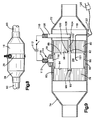
- FIG. 9 shows another embodiment of the present invention wherein the EHC is coaxially disposed between and in contact with portions of a ceramic monolith.
- a housing 70 having transition end caps 72 and 74 welded thereto for accommodating a standard exhaust pipe 60 as in Fig.8 and the oval or circular shape of the housing 70.
- Centrally located within the housing is a pair of axially spaced ceramic catalytic monoliths 78 and 80. These are inserted in the housing using a ceramic mat cushion 82.
- the mat 82 serves to reduce the opportunity for damage to the monolith units 78 and 80 due to vibration.
- the ceramic mat 82 also serves to restrain axial movement of the ceramic monoliths 78 and 80 and thus hold the core of the EHC against axial movement or telescoping especially in a downstream direction.
- an electrically heatable catalytic converter 84 built up in the same way as the electrically heatable catalytic unit 18 shown in Fig. 1 except that the band 86 need not have the projecting portion 26 (Figs. 4,5).
- the band 86 encircles the bundle of spirally wound overfolded corrugated thin metal strips 88 in the same manner as shown in the aforesaid Serial No. 587,219, Figs 1, 2, 2a, 3, 4 and 5 thereof.
- the bundle of steel rods 34 (Fig.
- the bore 92 in the downstream monolith 80 communicates with an axial bore 102 to accept a conducting rod 104 which is in turn welded at its inner end 108 to radially extending rod 106.
- the distal extremity of the rod 106 may be welded to the housing 70 at the point of exit, and threaded as at 110 to accept a support nut and a clamping nut (not shown) to hold a cable terminal from the ground pole of the voltage source 112 schematically shown.
- the positive terminal 113 is inserted through an insulated feedthrough 114 in any suitable manner (see, for example, the insulated feedthrough shown in Fig. 4, items 74, 76 in Serial No. 587,219, supra).
- the terminal 113 is welded at its inner end 116 to the band 86 surrounding and holding the bundle 84.
- the terminal 113 is threaded at its distal extremity 118 to accept and retain a cable from the voltage source 112.
- the monoliths 78 and 80 have from 16 to 400 cells per square inch, are desirably formed of extruded ceramic, each 1" to 3", preferably 2" in axial dimension, and catalysed with a noble metal catalyst.
- the upstream portion 78, or brick 78 may be omitted if desired.
- the bricks 78 and 80 are pushed tight against the EHC unit 84.
- the fit between the ceramic mat 82 and the housing 70 is tight to prevent slippage downstream and telescoping of the core 84 of the EHC.
- the ceramic unit O.D. may be the same or different from the EHC O.D.
- a thermocouple 119 is provided.
- the junction 121 is located within the EHC 84 with the leads extending through the housing 70 by means of an insulated feed through 123 and with an instrument plug 125.
- Fig. 10 shows in cross-section another embodiment of the present invention.
- the EHC 120 has a diameter less than the diameter of the ceramic portions 122 and 124.
- the upstream portion 122 is provided with a suitable bore 126 and recess 128.
- the downstream portion 124 is provided with a suitable bore 130 and a recess 132.
- the recesses 128 and 132 are provided to accommodate the extending portions 134 and 136 of the core bar 138.
- the downstream recess 132 is counter bored with a hole 140 to accept a current carrying axial bar 142 which is welded at its downstream extremity 144 to a radial current carrying bar 146 which extends through the housing 148.
- the extension through the housing is insulated from the housing 148 by a suitable feedthrough generally indicated at 150.
- a suitable feedthrough generally indicated at 150.
- the confronting faces 152 and 154 of the ceramic portions 122 and 124 are axially spaced about 0.5" to accommodate one or more radially extending current carrying bars 156 and 158.
- the inner ends of the bars 156 and 158, respectively, are welded to a retaining band 160 binding the plurality of overfolded corrugated thin metal foil strips forming the core 120 of the EHC as previously described.
- the outer ends of the bars 156 and 158 are conveniently welded to the housing 148.
- One the bars 156 or 158 may be extended and threaded at its distal extremity to accommodate a cable attachment lug, not shown.
- Fig. 10 also shows a thermocouple leading into the EHC 120 and exiting the housing 148 through a suitable feedthrough 162 for example, as shown in Fig. 3. of Serial No. 587,219.
- the ceramic blocks 122 and 124 are held in place within the housing 148 by a circumferential ceramic mat 164 compressed in the space between the housing 148 and the ceramic blocks or portions 122 and 124.
- the tight juxtaposition of the ceramic block or portion 124 against the downstream end of the core 120 prevents the core 120 from telescoping in a downstream direction.
- the composite which can be either a retrofitted device, as in Figs 1-8, or an OEM device, Figs. 9 and 10, is adapted to fit in a conventional exhaust system and has the durability to withstand rigorous testing by manufacturers and thereby prove durable under extreme user conditions.
- the devices of the present invention can be contained in a single can or housing located in the exhaust line under the floor of a vehicle or adjacent the engine exhaust manifold.
Landscapes
- Chemical & Material Sciences (AREA)
- Engineering & Computer Science (AREA)
- Chemical Kinetics & Catalysis (AREA)
- Health & Medical Sciences (AREA)
- Toxicology (AREA)
- Combustion & Propulsion (AREA)
- Mechanical Engineering (AREA)
- General Engineering & Computer Science (AREA)
- Environmental & Geological Engineering (AREA)
- Ceramic Engineering (AREA)
- Analytical Chemistry (AREA)
- General Chemical & Material Sciences (AREA)
- Oil, Petroleum & Natural Gas (AREA)
- Biomedical Technology (AREA)
- Materials Engineering (AREA)
- Organic Chemistry (AREA)
- Exhaust Gas After Treatment (AREA)
- Catalysts (AREA)
- Superconductors And Manufacturing Methods Therefor (AREA)
- Exhaust Gas Treatment By Means Of Catalyst (AREA)
Applications Claiming Priority (2)
| Application Number | Priority Date | Filing Date | Title |
|---|---|---|---|
| US07/606,129 US5140813A (en) | 1990-10-31 | 1990-10-31 | Composite catalytic converter |
| US606129 | 1996-02-23 |
Publications (2)
| Publication Number | Publication Date |
|---|---|
| EP0483708A1 true EP0483708A1 (de) | 1992-05-06 |
| EP0483708B1 EP0483708B1 (de) | 1996-12-18 |
Family
ID=24426669
Family Applications (1)
| Application Number | Title | Priority Date | Filing Date |
|---|---|---|---|
| EP91118304A Expired - Lifetime EP0483708B1 (de) | 1990-10-31 | 1991-10-26 | Katalytischer Umwandler in Verbundbauweise |
Country Status (6)
| Country | Link |
|---|---|
| US (1) | US5140813A (de) |
| EP (1) | EP0483708B1 (de) |
| JP (1) | JPH0626331A (de) |
| AT (1) | ATE146561T1 (de) |
| CA (1) | CA2050753A1 (de) |
| DE (1) | DE69123702D1 (de) |
Cited By (12)
| Publication number | Priority date | Publication date | Assignee | Title |
|---|---|---|---|---|
| EP0572827A1 (de) * | 1992-06-03 | 1993-12-08 | Corning Incorporated | Beheizte Zellsubstrate |
| US5294411A (en) * | 1989-04-17 | 1994-03-15 | Emitec Gesellschaft Fuer Emissionstechnologie Mbh | Honeycomb body with heatable catalytic active coating |
| GB2273637A (en) * | 1992-12-15 | 1994-06-22 | Ngk Insulators Ltd | Honeycomb heater |
| FR2703206A1 (fr) * | 1993-03-26 | 1994-09-30 | Ecia Equip Composants Ind Auto | Dispositif de chauffage d'un élément de purification catalytique des gaz d'échappement d'un moteur notamment de véhicule automobile. |
| US5393499A (en) * | 1992-06-03 | 1995-02-28 | Corning Incorporated | Heated cellular substrates |
| US5409668A (en) * | 1992-06-03 | 1995-04-25 | Corning Incorporated | Method for controlling the conductance of a heated cellular substrate |
| EP0635627A3 (de) * | 1993-05-25 | 1995-05-31 | Grace W R & Co | Kombinierter, elektrisch heizbarer Umwandler. |
| WO1996027078A1 (en) * | 1995-03-01 | 1996-09-06 | Ab Volvo | Device for catalytic purification of exhaust gases |
| DE19602266A1 (de) * | 1996-01-23 | 1997-07-24 | Bayerische Motoren Werke Ag | Elektrisch beheizbarer Abgas-Katalysator einer Brennkraftmaschine |
| EP1297885A1 (de) | 2001-09-28 | 2003-04-02 | Volvo Teknisk Utveckling AB | Poröser Katalysator, Verfahren und Anordnung zur katalytischen Konversion von Abgasen |
| US7033969B1 (en) | 1997-12-10 | 2006-04-25 | Volvo Car Corporation | Porous material, method and arrangement for catalytic conversion of exhaust gases |
| CN109496249A (zh) * | 2016-08-04 | 2019-03-19 | 大陆汽车有限公司 | 具有施加的扁平电导体的金属薄膜及使用所述薄膜生产的蜂窝状本体 |
Families Citing this family (47)
| Publication number | Priority date | Publication date | Assignee | Title |
|---|---|---|---|---|
| DE4035971A1 (de) * | 1990-11-12 | 1992-05-14 | Emitec Emissionstechnologie | Beheizbare katalysatoranordnung fuer die abgasreinigung von verbrennungsmotoren |
| US5525309A (en) * | 1991-01-31 | 1996-06-11 | Emitec Gesellschaft Fuer Emissionstechnologie Mbh | Honeycomb body with a plurality of disks braced against one another |
| JP2547177Y2 (ja) * | 1991-10-07 | 1997-09-10 | 日産自動車株式会社 | 内燃機関の排気装置 |
| JP3035035B2 (ja) * | 1991-11-21 | 2000-04-17 | 日本碍子株式会社 | ヒーターユニット |
| US5254840A (en) * | 1991-12-12 | 1993-10-19 | Corning Incorporated | Mounting for metal honeycomb structures |
| US5355973A (en) * | 1992-06-02 | 1994-10-18 | Donaldson Company, Inc. | Muffler with catalytic converter arrangement; and method |
| US5426269A (en) * | 1992-06-02 | 1995-06-20 | Donaldson Company, Inc. | Muffler with catalytic converter arrangement; and method |
| US5285640A (en) * | 1992-07-21 | 1994-02-15 | Olivo John R | Integrated post-engine emissions heater, catalytic converter and muffler |
| JP2559365Y2 (ja) * | 1992-08-26 | 1998-01-14 | 本田技研工業株式会社 | 内燃機関の排気浄化装置 |
| US5582805A (en) * | 1992-12-21 | 1996-12-10 | Toyota Jidosha Kabushiki Kaisha | Electrically heated catalytic apparatus |
| DE9321388U1 (de) * | 1993-02-08 | 1997-10-30 | Emitec Gesellschaft für Emissionstechnologie mbH, 53797 Lohmar | Elektrisch isolierende gasdichte Durchführung mindestens eines elektrischen Leiters durch einen metallischen Mantel |
| DE69415280T2 (de) * | 1993-05-12 | 1999-04-29 | Nippon Steel Corp., Tokio/Tokyo | Verfahren zum löten von einer warmfesten legierung, die mit einem isolierenden oxidischen film beschichtet ist, vorgeheitzter metallischer träger zum reinigen von abgasen und verfahren zum erzeugen von diesem |
| US5423904A (en) * | 1993-05-28 | 1995-06-13 | Dasgupta; Sankar | Exhaust gas filter |
| DE4341380A1 (de) * | 1993-12-04 | 1995-06-14 | Degussa | Verfahren zur Beschleunigung der Aufheizung von Feststoffkatalysatoren durch Zufuhr von Hilfsenergie |
| US5456890A (en) * | 1993-12-09 | 1995-10-10 | W. R. Grace & Co.-Conn. | Combined electrically heatable and light-off converter |
| US5501842A (en) * | 1994-08-30 | 1996-03-26 | Corning Incorporated | Axially assembled enclosure for electrical fluid heater and method |
| US5687787A (en) * | 1995-08-16 | 1997-11-18 | Northrop Grumman Corporation | Fiber reinforced ceramic matrix composite internal combustion engine exhaust manifold |
| US5879640A (en) * | 1995-08-16 | 1999-03-09 | Northrop Grumman Corporation | Ceramic catalytic converter |
| US5740788A (en) * | 1995-08-16 | 1998-04-21 | Northrop Grumman Corporation | Fiber reinforced ceramic matrix composite piston and cylinder/sleeve for an internal combustion engine |
| IL123300A0 (en) * | 1995-08-16 | 1998-09-24 | Northrop Grumman Corp | Reducing wear between structural fiber reinforced ceramic matrix composite automotive engine parts in sliding contacting relationship |
| US5632320A (en) * | 1995-08-16 | 1997-05-27 | Northrop Grumman Corporation | Methods and apparatus for making ceramic matrix composite lined automotive parts and fiber reinforced ceramic matrix composite automotive parts |
| US5692373A (en) * | 1995-08-16 | 1997-12-02 | Northrop Grumman Corporation | Exhaust manifold with integral catalytic converter |
| US5560455A (en) * | 1995-08-16 | 1996-10-01 | Northrop Grumman Corporation | Brakes rotors/drums and brake pads particularly adapted for aircraft/truck/train/ and other heavy duty applications |
| US5657729A (en) * | 1995-08-16 | 1997-08-19 | Northrop Grumman Corporation | Fiber reinforced ceramic matrix composite cylinder head and cylinder head liner for an internal combustion engine |
| US5582784A (en) * | 1995-08-16 | 1996-12-10 | Northrop Grumman Corporation | Method of making ceramic matrix composite/ceramic foam panels |
| US5638779A (en) * | 1995-08-16 | 1997-06-17 | Northrop Grumman Corporation | High-efficiency, low-pollution engine |
| US5660399A (en) * | 1995-08-16 | 1997-08-26 | Northrop Grumman Corporation | Piston rings particularly suited for use with ceramic matrix composite pistons and cylinders |
| US5643512A (en) * | 1995-08-16 | 1997-07-01 | Northrop Grumman Corporation | Methods for producing ceramic foams using pre-ceramic resins combined with liquid phenolic resin |
| DE19812321A1 (de) * | 1998-03-20 | 1999-09-30 | Siemens Ag | Katalysatorkörper |
| US6217832B1 (en) * | 1998-04-30 | 2001-04-17 | Catalytica, Inc. | Support structures for a catalyst |
| JP2002058748A (ja) | 1998-12-11 | 2002-02-26 | Paiorakkusu:Kk | カテーテル用ガイドワイヤ、及びカテーテル用ガイドワイヤの製造方法 |
| US6265078B1 (en) | 1999-09-09 | 2001-07-24 | Northrop Grumman Corporation | Reducing wear between structural fiber reinforced ceramic matrix composite automotive engine parts in sliding contacting relationship |
| EP1500799B1 (de) * | 2002-04-11 | 2007-10-24 | Ibiden Co., Ltd. | Wabenfilter zur reinigung von abgas |
| US7774936B2 (en) * | 2004-08-02 | 2010-08-17 | Emcon Technologies Llc | Catalytic converter and associated method of assembly |
| US7451594B2 (en) * | 2004-10-01 | 2008-11-18 | Donaldson Company, Inc. | Exhaust flow distribution device |
| US8110151B2 (en) * | 2006-04-03 | 2012-02-07 | Donaldson Company, Inc. | Exhaust flow distribution device |
| US9009967B2 (en) * | 2008-07-31 | 2015-04-21 | Caterpillar Inc. | Composite catalyst substrate |
| JP2010203419A (ja) * | 2009-03-06 | 2010-09-16 | Toyota Motor Corp | ハイブリッド車両用排ガス浄化装置 |
| US8997470B2 (en) * | 2010-03-17 | 2015-04-07 | Toyota Jidosha Kabushiki Kaisha | Exhaust gas purifying device for internal combustion engine |
| DE102011110664A1 (de) * | 2011-08-19 | 2013-02-21 | Emitec Gesellschaft Für Emissionstechnologie Mbh | Vorrichtung zur Behandlung von Abgasen |
| US10598068B2 (en) | 2015-12-21 | 2020-03-24 | Emissol, Llc | Catalytic converters having non-linear flow channels |
| JP7183875B2 (ja) * | 2019-03-08 | 2022-12-06 | トヨタ自動車株式会社 | 内燃機関 |
| JP2020143649A (ja) * | 2019-03-08 | 2020-09-10 | トヨタ自動車株式会社 | 内燃機関 |
| DE102019218354A1 (de) | 2019-11-27 | 2021-05-27 | Vitesco Technologies GmbH | Vorrichtung zur Abgasnachbehandlung |
| DE102019219150B4 (de) * | 2019-12-09 | 2025-01-23 | Vitesco Technologies GmbH | Vorrichtung zur Abgasnachbehandlung und Verfahren zur Herstellung dieser |
| DE102021122082A1 (de) * | 2021-08-26 | 2023-03-02 | Purem GmbH | Abgasheizer und Verfahren zur Herstellung eines Abgasheizers |
| DE102022131967A1 (de) * | 2022-12-02 | 2024-06-13 | Purem GmbH | Abstützeinheit zur Abstützung eines Heizleiters eines Abgasheizers an einer Trägerstruktur |
Citations (5)
| Publication number | Priority date | Publication date | Assignee | Title |
|---|---|---|---|---|
| US3770389A (en) * | 1971-11-11 | 1973-11-06 | Ford Motor Co | Catalytic converter with electrically resistive catalyst support |
| DE2333092A1 (de) * | 1973-06-29 | 1975-01-16 | Volkswagenwerk Ag | Abgasreinigungsanlage |
| US4523935A (en) * | 1981-08-03 | 1985-06-18 | Nippon Soken, Inc. | Electrical heater retained in a porous ceramic structure |
| US4662911A (en) * | 1982-03-18 | 1987-05-05 | Nippondenso Co., Ltd. | Equipment for trapping particulates in engine exhaust gas |
| US4928485A (en) * | 1989-06-06 | 1990-05-29 | W. R. Grace & Co.,-Conn. | Metallic core member for catalytic converter and catalytic converter containing same |
Family Cites Families (10)
| Publication number | Priority date | Publication date | Assignee | Title |
|---|---|---|---|---|
| DE563757C (de) * | 1929-08-12 | |||
| US3795524A (en) * | 1971-03-01 | 1974-03-05 | Minnesota Mining & Mfg | Aluminum borate and aluminum borosilicate articles |
| US3768982A (en) * | 1971-06-22 | 1973-10-30 | Ford Motor Co | Catalytic converter with electrically preheated catalyst |
| US4414023A (en) * | 1982-04-12 | 1983-11-08 | Allegheny Ludlum Steel Corporation | Iron-chromium-aluminum alloy and article and method therefor |
| US4711009A (en) * | 1986-02-18 | 1987-12-08 | W. R. Grace & Co. | Process for making metal substrate catalytic converter cores |
| JPH0540251Y2 (de) * | 1986-10-23 | 1993-10-13 | ||
| US4810588A (en) * | 1988-05-24 | 1989-03-07 | W. R. Grace & Co.-Conn. | Nonnesting, straight corrugation metal foil and method for making same |
| DE8910471U1 (de) * | 1989-09-01 | 1991-01-10 | Nixdorf Computer Ag, 4790 Paderborn | Halterungsvorrichtung für ein elektrisches Bauteil |
| DE8910470U1 (de) * | 1989-09-01 | 1991-01-03 | Lucas Industries P.L.C., Birmingham, West Midlands | Pneumatisch-hydraulischer Druckerzeuger, insbesondere für Fahrzeugbremsanlagen |
| JP2913868B2 (ja) * | 1991-03-08 | 1999-06-28 | トヨタ自動車株式会社 | 内燃機関の排ガス浄化装置 |
-
1990
- 1990-10-31 US US07/606,129 patent/US5140813A/en not_active Expired - Fee Related
-
1991
- 1991-09-05 CA CA002050753A patent/CA2050753A1/en not_active Abandoned
- 1991-10-24 JP JP3303867A patent/JPH0626331A/ja active Pending
- 1991-10-26 DE DE69123702T patent/DE69123702D1/de not_active Expired - Lifetime
- 1991-10-26 EP EP91118304A patent/EP0483708B1/de not_active Expired - Lifetime
- 1991-10-26 AT AT91118304T patent/ATE146561T1/de not_active IP Right Cessation
Patent Citations (5)
| Publication number | Priority date | Publication date | Assignee | Title |
|---|---|---|---|---|
| US3770389A (en) * | 1971-11-11 | 1973-11-06 | Ford Motor Co | Catalytic converter with electrically resistive catalyst support |
| DE2333092A1 (de) * | 1973-06-29 | 1975-01-16 | Volkswagenwerk Ag | Abgasreinigungsanlage |
| US4523935A (en) * | 1981-08-03 | 1985-06-18 | Nippon Soken, Inc. | Electrical heater retained in a porous ceramic structure |
| US4662911A (en) * | 1982-03-18 | 1987-05-05 | Nippondenso Co., Ltd. | Equipment for trapping particulates in engine exhaust gas |
| US4928485A (en) * | 1989-06-06 | 1990-05-29 | W. R. Grace & Co.,-Conn. | Metallic core member for catalytic converter and catalytic converter containing same |
Cited By (19)
| Publication number | Priority date | Publication date | Assignee | Title |
|---|---|---|---|---|
| US5294411A (en) * | 1989-04-17 | 1994-03-15 | Emitec Gesellschaft Fuer Emissionstechnologie Mbh | Honeycomb body with heatable catalytic active coating |
| US5393499A (en) * | 1992-06-03 | 1995-02-28 | Corning Incorporated | Heated cellular substrates |
| EP0572827A1 (de) * | 1992-06-03 | 1993-12-08 | Corning Incorporated | Beheizte Zellsubstrate |
| US5409668A (en) * | 1992-06-03 | 1995-04-25 | Corning Incorporated | Method for controlling the conductance of a heated cellular substrate |
| GB2273637B (en) * | 1992-12-15 | 1995-12-20 | Ngk Insulators Ltd | Honeycomb heater |
| GB2273637A (en) * | 1992-12-15 | 1994-06-22 | Ngk Insulators Ltd | Honeycomb heater |
| US5533167A (en) * | 1992-12-15 | 1996-07-02 | Ngk Insulators, Ltd. | Honeycomb heater element having front region adapted to heat quickly |
| US5664049A (en) * | 1992-12-15 | 1997-09-02 | Ngk Insulators, Ltd. | Honeycomb heater |
| FR2703206A1 (fr) * | 1993-03-26 | 1994-09-30 | Ecia Equip Composants Ind Auto | Dispositif de chauffage d'un élément de purification catalytique des gaz d'échappement d'un moteur notamment de véhicule automobile. |
| EP0635627A3 (de) * | 1993-05-25 | 1995-05-31 | Grace W R & Co | Kombinierter, elektrisch heizbarer Umwandler. |
| US5441706A (en) * | 1993-05-25 | 1995-08-15 | W. R. Grace & Co.-Conn. | Combined electrically heatable converter body |
| US5996339A (en) * | 1995-03-01 | 1999-12-07 | Ab Volvo | Device for catalytic purification of exhaust gases |
| WO1996027078A1 (en) * | 1995-03-01 | 1996-09-06 | Ab Volvo | Device for catalytic purification of exhaust gases |
| DE19602266A1 (de) * | 1996-01-23 | 1997-07-24 | Bayerische Motoren Werke Ag | Elektrisch beheizbarer Abgas-Katalysator einer Brennkraftmaschine |
| US7033969B1 (en) | 1997-12-10 | 2006-04-25 | Volvo Car Corporation | Porous material, method and arrangement for catalytic conversion of exhaust gases |
| EP1297885A1 (de) | 2001-09-28 | 2003-04-02 | Volvo Teknisk Utveckling AB | Poröser Katalysator, Verfahren und Anordnung zur katalytischen Konversion von Abgasen |
| CN109496249A (zh) * | 2016-08-04 | 2019-03-19 | 大陆汽车有限公司 | 具有施加的扁平电导体的金属薄膜及使用所述薄膜生产的蜂窝状本体 |
| CN109496249B (zh) * | 2016-08-04 | 2021-06-04 | 大陆汽车有限公司 | 一种蜂窝状本体 |
| US11092051B2 (en) | 2016-08-04 | 2021-08-17 | Vitesco Technologies GmbH | Metallic film having applied flat electrical conductor and honeycomb body produced using said film |
Also Published As
| Publication number | Publication date |
|---|---|
| JPH0626331A (ja) | 1994-02-01 |
| EP0483708B1 (de) | 1996-12-18 |
| DE69123702D1 (de) | 1997-01-30 |
| ATE146561T1 (de) | 1997-01-15 |
| CA2050753A1 (en) | 1992-05-01 |
| US5140813A (en) | 1992-08-25 |
Similar Documents
| Publication | Publication Date | Title |
|---|---|---|
| EP0483708B1 (de) | Katalytischer Umwandler in Verbundbauweise | |
| US5177961A (en) | Upstream collimator for electrically heatable catalytic converter | |
| EP0483705B1 (de) | Struktur für einen elektrisch heizbaren katalytischen Kern | |
| US5140812A (en) | Core for an electrically heatable catalytic converter | |
| US5174968A (en) | Structure for electrically heatable catalytic core | |
| US4976929A (en) | Electrically heated catalytic converter | |
| US5232671A (en) | Core for a catalytic converter | |
| US5238650A (en) | Electrode feed through | |
| US5170624A (en) | Composite catalytic converter | |
| EP0687807B1 (de) | Heizungseinheit und katalytischer Umwandler | |
| US5149508A (en) | Parallel path catalytic converter | |
| EP0635627B1 (de) | Kombinierter, elektrisch heizbarer Umwandler | |
| US5456890A (en) | Combined electrically heatable and light-off converter | |
| US5240682A (en) | Reinforced corrugated thin metal foil strip useful in a catalytic converter core, a catalytic converter core containing said strip and an electrically heatable catalytic converter containing said core | |
| US5384099A (en) | Core element for catalytic converter | |
| EP0571059B1 (de) | Kernelement für Katalysator | |
| US5546746A (en) | Core element useful in a combined electrically heatable and light-off converter | |
| US5628928A (en) | Method for reducing the potential difference in an electrically heatable converter by connecting the strip heater to corrugated strip with an electrical conductor | |
| EP0569109A1 (de) | Kernelement für Katalysator | |
| US5308591A (en) | Core body for catalytic converter | |
| US5146744A (en) | Electrically heatable catalytic converter insert | |
| EP0677649B1 (de) | Kernelement für einen kombinierten, elektrisch beheizten und selbsteinleitenden Umwandler | |
| WO1995016110A1 (en) | Improved combined electrically heatable and light-off converter | |
| JPH02277916A (ja) | 並列パス触媒コンバーター |
Legal Events
| Date | Code | Title | Description |
|---|---|---|---|
| PUAI | Public reference made under article 153(3) epc to a published international application that has entered the european phase |
Free format text: ORIGINAL CODE: 0009012 |
|
| AK | Designated contracting states |
Kind code of ref document: A1 Designated state(s): AT BE CH DE DK ES FR GB GR IT LI LU NL SE |
|
| 17P | Request for examination filed |
Effective date: 19921005 |
|
| 17Q | First examination report despatched |
Effective date: 19930810 |
|
| GRAG | Despatch of communication of intention to grant |
Free format text: ORIGINAL CODE: EPIDOS AGRA |
|
| GRAH | Despatch of communication of intention to grant a patent |
Free format text: ORIGINAL CODE: EPIDOS IGRA |
|
| GRAH | Despatch of communication of intention to grant a patent |
Free format text: ORIGINAL CODE: EPIDOS IGRA |
|
| GRAA | (expected) grant |
Free format text: ORIGINAL CODE: 0009210 |
|
| RAP1 | Party data changed (applicant data changed or rights of an application transferred) |
Owner name: W.R. GRACE & CO.-CONN. |
|
| AK | Designated contracting states |
Kind code of ref document: B1 Designated state(s): AT BE CH DE DK ES FR GB GR IT LI LU NL SE |
|
| PG25 | Lapsed in a contracting state [announced via postgrant information from national office to epo] |
Ref country code: IT Free format text: LAPSE BECAUSE OF FAILURE TO SUBMIT A TRANSLATION OF THE DESCRIPTION OR TO PAY THE FEE WITHIN THE PRE;WARNING: LAPSES OF ITALIAN PATENTS WITH EFFECTIVE DATE BEFORE 2007 MAY HAVE OCCURRED AT ANY TIME BEFORE 2007. THE CORRECT EFFECTIVE DATE MAY BE DIFFERENT FROM THE ONE RECORDED.SCRIBED TIME-LIMIT Effective date: 19961218 Ref country code: LI Effective date: 19961218 Ref country code: NL Free format text: LAPSE BECAUSE OF FAILURE TO SUBMIT A TRANSLATION OF THE DESCRIPTION OR TO PAY THE FEE WITHIN THE PRESCRIBED TIME-LIMIT Effective date: 19961218 Ref country code: FR Effective date: 19961218 Ref country code: DK Effective date: 19961218 Ref country code: ES Free format text: THE PATENT HAS BEEN ANNULLED BY A DECISION OF A NATIONAL AUTHORITY Effective date: 19961218 Ref country code: GR Free format text: LAPSE BECAUSE OF FAILURE TO SUBMIT A TRANSLATION OF THE DESCRIPTION OR TO PAY THE FEE WITHIN THE PRESCRIBED TIME-LIMIT Effective date: 19961218 Ref country code: BE Effective date: 19961218 Ref country code: CH Effective date: 19961218 Ref country code: AT Effective date: 19961218 |
|
| REF | Corresponds to: |
Ref document number: 146561 Country of ref document: AT Date of ref document: 19970115 Kind code of ref document: T |
|
| REF | Corresponds to: |
Ref document number: 69123702 Country of ref document: DE Date of ref document: 19970130 |
|
| PG25 | Lapsed in a contracting state [announced via postgrant information from national office to epo] |
Ref country code: SE Effective date: 19970318 |
|
| PG25 | Lapsed in a contracting state [announced via postgrant information from national office to epo] |
Ref country code: DE Effective date: 19970319 |
|
| EN | Fr: translation not filed | ||
| NLV1 | Nl: lapsed or annulled due to failure to fulfill the requirements of art. 29p and 29m of the patents act | ||
| REG | Reference to a national code |
Ref country code: CH Ref legal event code: PL |
|
| PLBE | No opposition filed within time limit |
Free format text: ORIGINAL CODE: 0009261 |
|
| STAA | Information on the status of an ep patent application or granted ep patent |
Free format text: STATUS: NO OPPOSITION FILED WITHIN TIME LIMIT |
|
| PG25 | Lapsed in a contracting state [announced via postgrant information from national office to epo] |
Ref country code: GB Free format text: LAPSE BECAUSE OF NON-PAYMENT OF DUE FEES Effective date: 19971026 |
|
| PG25 | Lapsed in a contracting state [announced via postgrant information from national office to epo] |
Ref country code: LU Free format text: LAPSE BECAUSE OF NON-PAYMENT OF DUE FEES Effective date: 19971031 |
|
| 26N | No opposition filed | ||
| GBPC | Gb: european patent ceased through non-payment of renewal fee |
Effective date: 19971026 |