EP0483823A2 - Gerät zur Aufnahme von Videosignalen mit rotierenden Köpfen - Google Patents
Gerät zur Aufnahme von Videosignalen mit rotierenden Köpfen Download PDFInfo
- Publication number
- EP0483823A2 EP0483823A2 EP91118557A EP91118557A EP0483823A2 EP 0483823 A2 EP0483823 A2 EP 0483823A2 EP 91118557 A EP91118557 A EP 91118557A EP 91118557 A EP91118557 A EP 91118557A EP 0483823 A2 EP0483823 A2 EP 0483823A2
- Authority
- EP
- European Patent Office
- Prior art keywords
- video signal
- rotating
- rotational phase
- recording
- rotational
- Prior art date
- Legal status (The legal status is an assumption and is not a legal conclusion. Google has not performed a legal analysis and makes no representation as to the accuracy of the status listed.)
- Granted
Links
- 238000000034 method Methods 0.000 description 8
- 239000002131 composite material Substances 0.000 description 5
- 238000010586 diagram Methods 0.000 description 5
- 230000000694 effects Effects 0.000 description 4
- 238000000926 separation method Methods 0.000 description 4
- 238000003780 insertion Methods 0.000 description 3
- 230000037431 insertion Effects 0.000 description 3
- 238000013459 approach Methods 0.000 description 2
- 238000012986 modification Methods 0.000 description 2
- 230000004048 modification Effects 0.000 description 2
- 238000010276 construction Methods 0.000 description 1
- 230000003111 delayed effect Effects 0.000 description 1
- 230000007274 generation of a signal involved in cell-cell signaling Effects 0.000 description 1
- 230000001771 impaired effect Effects 0.000 description 1
- 238000012545 processing Methods 0.000 description 1
- 230000000087 stabilizing effect Effects 0.000 description 1
Images


Classifications
-
- H—ELECTRICITY
- H04—ELECTRIC COMMUNICATION TECHNIQUE
- H04N—PICTORIAL COMMUNICATION, e.g. TELEVISION
- H04N9/00—Details of colour television systems
- H04N9/79—Processing of colour television signals in connection with recording
- H04N9/87—Regeneration of colour television signals
-
- G—PHYSICS
- G11—INFORMATION STORAGE
- G11B—INFORMATION STORAGE BASED ON RELATIVE MOVEMENT BETWEEN RECORD CARRIER AND TRANSDUCER
- G11B15/00—Driving, starting or stopping record carriers of filamentary or web form; Driving both such record carriers and heads; Guiding such record carriers or containers therefor; Control thereof; Control of operating function
- G11B15/02—Control of operating function, e.g. switching from recording to reproducing
- G11B15/12—Masking of heads; circuits for Selecting or switching of heads between operative and inoperative functions or between different operative functions or for selection between operative heads; Masking of beams, e.g. of light beams
- G11B15/14—Masking or switching periodically, e.g. of rotating heads
-
- G—PHYSICS
- G11—INFORMATION STORAGE
- G11B—INFORMATION STORAGE BASED ON RELATIVE MOVEMENT BETWEEN RECORD CARRIER AND TRANSDUCER
- G11B15/00—Driving, starting or stopping record carriers of filamentary or web form; Driving both such record carriers and heads; Guiding such record carriers or containers therefor; Control thereof; Control of operating function
- G11B15/18—Driving; Starting; Stopping; Arrangements for control or regulation thereof
- G11B15/1808—Driving of both record carrier and head
- G11B15/1875—Driving of both record carrier and head adaptations for special effects or editing
-
- G—PHYSICS
- G11—INFORMATION STORAGE
- G11B—INFORMATION STORAGE BASED ON RELATIVE MOVEMENT BETWEEN RECORD CARRIER AND TRANSDUCER
- G11B15/00—Driving, starting or stopping record carriers of filamentary or web form; Driving both such record carriers and heads; Guiding such record carriers or containers therefor; Control thereof; Control of operating function
- G11B15/18—Driving; Starting; Stopping; Arrangements for control or regulation thereof
- G11B15/46—Controlling, regulating, or indicating speed
- G11B15/467—Controlling, regulating, or indicating speed in arrangements for recording or reproducing wherein both record carriers and heads are driven
- G11B15/473—Controlling, regulating, or indicating speed in arrangements for recording or reproducing wherein both record carriers and heads are driven by controlling the speed of the heads
- G11B15/4731—Controlling, regulating, or indicating speed in arrangements for recording or reproducing wherein both record carriers and heads are driven by controlling the speed of the heads control of headwheel rotation
-
- H—ELECTRICITY
- H04—ELECTRIC COMMUNICATION TECHNIQUE
- H04N—PICTORIAL COMMUNICATION, e.g. TELEVISION
- H04N5/00—Details of television systems
- H04N5/76—Television signal recording
- H04N5/78—Television signal recording using magnetic recording
- H04N5/782—Television signal recording using magnetic recording on tape
-
- H—ELECTRICITY
- H04—ELECTRIC COMMUNICATION TECHNIQUE
- H04N—PICTORIAL COMMUNICATION, e.g. TELEVISION
- H04N9/00—Details of colour television systems
- H04N9/79—Processing of colour television signals in connection with recording
Definitions
- This invention relates to a video signal recording apparatus which records an interlaced video signal, which forms one frame using a plurality of fields, on a recording medium using rotating heads.
- VCR video cassette recorder
- the field to be recorded by one of two heads having different azimuths is in general assigned to either one of the two fields of each frame.
- horizintal synchronizing signals continue even at connecting portions of recorded signals present in connected recording, insertion recording (wherein a picture recorded at a different time period is inserted) or the like. Hence, an image is not disturbed in a reproducing operation.
- the rotational phase of a rotating head cylinder having two rotating heads must be controlled in synchronization with each frame of the video signal.
- a long time is needed to synchronize the rotational phase of the rotating head cylinder with a desired control target phase.
- the phase of the rotating head cylinder must be shifted 180°, and a very long time is needed until the rotating head cylinder reaches a servo-locked state. Accordingly, when performing connected recording, insertion recording or the like, the time after the video signal to be recorded has been input and the control of the rotational phase of the rotating head has been started until recording is actually started must be set long, causing a delay of the timing of recording.
- a video signal recording appartus comprising (a) a rotating cylinder provided with a plurality of rotating heads having different rotational phases, (b) recording means for sequentially supplying the plurality of rotating heads with a video signal according to an interlaced scanning method, and (c) switching means for relatively switching a phase difference between a rotational phase of the rotating cylinder and a vertical synchronizing signal of the video signal supplied to the plurality of rotating heads from the recording means.
- a video signal recording apparatus comprises (a) a rotating cylinder provided with a plurality of rotating heads having different rotational phases, (b) recording means for sequentially supplying said plurality of rotating heads with a video signal having interlaced video information, and (c) rotational phase control means for controlling a rotational phase of said rotating cylinder relative to a vertical synchronizing signal of said video signal, said rotational phase control means always including a plurality of objective rotational phases.
- a video signal recording apparatus includes (a) a rotating cylinder provided with a plurality of rotating heads having different rotational phases, (b) recording means for sequentially supplying said plurality of rotating heads with an n:1 interlaced video signal, and (c) rotational phase control means for controlling a rotational phase of said rotating cylinder, said rotational phase control means being capable of shifting an objective rotational phase for a 1/n horizontal scanning period of said video signal.
- a video signal recording apparatus comprises (a) input means for inputting a video signal having interlaced fields, (b) recording means for recording said video signal on a recording medium sequentially using a plurality of rotating heads, and (c) rotational phase control means for controlling rotational phases of said rotating heads, said rotational phase control means being capable of relatively switching the rotational phase of a rotating head relative to a vertical synchronizing signal of the video signal recorded by said recording means for a period corresponding to a phase different between a vertical synchronizing signal and a horizontal synchronizing signal of each field.
- a signal (hereinafter termed a PG signal) output from the PG head 13 represents the rotational phase of the rotating cylinder 10.
- a pulse for example, is output every time the cylinder 10 rotates 180°.
- the PG signal is input to a head switching signal generation circuit 9, which generates a head switching pulse (HSP) which becomes a high level (Hi) with a timing that the head HA traces a video signal recording region on the magnetic tape, and becomes a low level (Lo) with a timing that the head HB traces a video signal recording region.
- HSP head switching pulse
- the frequency of the HSP is 30 Hz, and the HSP is input to a phase target control circuit 5 and the phase comparison circuit 6 (to be described later).
- the phase comparison circuit 6 compares the phases of the vertical synchronizing signal and the HSP, and outputs a phase error signal so that the phase difference between each vertical synchronizing signal and the HSP becomes a predetermined phase difference (target phase difference).
- the phase error signal is supplied to the cylinder motor control circuit 8, and is added to a speed error signal to control the cylinder motor 11.
- the HSP and the vertical synchronizing signal that is, the rotating heads HA and HB and the vertical synchronizing signal are thereby controlled so as to achieve the target phase difference.
- the system is configured so as to be in a control locked state no matter when the HSP is in the predetermined phase relationship with any vertical synchronizing signal. That is, since two control target phases for the rotating cylinder 10 are present for every 180°, the heads HA and HB record either the first or second field. Accordingly, the time needed for reaching control lock of the rotational phase is greatly shortened as compared with when each of the heads HA and HB records only either one of the first and second fields, that is, when the rotating cylinder 10 has only one control target phase, as in the conventional approach.
- the video signal recorded when the HSP is Hi may be of either the first field or the second field
- the control target phase of the rotating cylinder 10 is shifted by 1 ⁇ 2 H when the head HA records the video signal of the second field.
- the field discrimination circuit 4 receives the composite cynchronizing signal from the synchronising signal separation circuit 2, and discriminates whether the input video signal is of the first field or the second field.
- the method of such discrimination there have been known, for example, a method of detecting a phase difference between each vertical synchronizing signal and horizontal synchronizing signal, and a method of counting equalizing pulses within a vertical retrace line period. Since the specific configuration of the field discrimination circuit 4 is not directly related to the present invention, explanation thereof will be omitted.
- the field discrimination circuit 4 outputs a field discrimination signal which rises after the vertical retrace line period in the video signal of the first field, and falls after the vertical retrace line period in the video signal of the second field using a known method as described above.
- the field discrimination signal is supplied to the phase target control circuit 5, and is latched with the rise timing of the HSP.
- the vertical synchronizing signal is subjected to phase lock at a few H after the edge of the HSP.
- the above-described latch output becomes Lo.
- the latch output becomes Hi.
- the latch output is supplied to the phase comparison circuit 6 as a phase target control signal, and shifts the control target phase of the cylinder 10 by 0.5 H when the latch output is Hi.
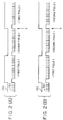
- FIGS. 3(A) and 3(B) are diagrams showing the phase relationship between the first field and second field signals and the rise of the HSP, respectively.
- the system is controlled so that the phase difference between the leading edge of the vertical synchronizing signal of the first field and the rise of the HSP becomes a predetermined target phase difference c (corresponding to 6H).
- the phase difference between the leading edge of the vertical synchronizing signal of the second field and the fall of the HSP also becomes 6H.
- phase target control signal When the phase target control signal is Hi, that is, when the head HA records the second field, the control target phase of the cylinder 10 shifts 0.5 H.
- the system is controlled so that the phase difference between the leading edge of the vertical synchronizing signal of the second field and the rise of the HSP becomes a value e (corresponding to 6.5 H) obtained by adding a shift amount d to the predetermined target value c.
- the phase difference between the leading edge of the vertical synchronizing signal of the first field and the rise of the HSP also becomes 6.5 H.
- the shift operation of the control target phase in the phase comparison circuit 6 differs according to the configuration of the circuit 6. If, for example, the circuit 6 comprises an analog circuit, the shift operation can be achieved by delaying the HSP 0.5 H. If the circuit 6 is configured so as to count the number of clock pulses between the rise of the HSP and the leading edge of the vertical synchronizing signal, the shift operation may also be achieved by subtracting the number of clock pulses generated during 0.5 H from the count value.
- the relationship between the horizontal synchronizing signal and the rotational phase of the head is always the same no matter when each of the heads HA and HB records any of the fields, and continuity of horizontal synchronizing signals is not impaired even if connected portions of the video signal are present due to connected recording, insertion recording or the like.
- the rotation of the heads HA and HB may be phase-locked to the vertical synchronizing signal of either the first field or the second field, the servo synchronizing time for the rotating head is shortened, and the time period after the start of the rotating head until recording is actually started can be shortened.
- such scanning can be performed by a very simple change in the configuration, that is, shifting of the phase control target, and no additional circuitry is needed particularly when software servo operation utilizing a microcomputer and the like is performed.
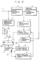
- FIG. 4 is a diagram showing the schematic configuration of a two-head helical scanning VCR according to another embodiment of the present invention.
- the same components as those shown in FIG. 1 are indicated by the same reference numerals, and further explanation thereof will be omitted.
- a delay line control circuit 15 becomes Lo when the head HA records the video signal of the first field, and becomes Hi when the head HA records the video signal of the second field, as the phase target control circuit 5 shown in FIG. 1.
- a switch 17 is connected to side H. Consequently, when the head HA records the signal of the second field, the signal to be recorded is delayed 1 ⁇ 2 H by a 1 ⁇ 2 horizontal scanning period delay circuit (1 ⁇ 2H DL).
- the phases of the vertical synchronizing signal of the video signal to be recorded and the HSP are relatively shifted by 1 ⁇ 2 H
- the same effects may also be, in general, obtained by shifting the phases by (n + 1 ⁇ 2) H (n is an integer).
- the head configuration is not limited to this configuration.
- the present invention may also be applied when, for example, a magnetic tape is wound around a rotating cylinder over an angular range of at least 270°, and a video signal is sequentially recorded for every field using four heads having phases different from one another by 90° (270°). That is, the same effects may be obtained by configuring servo circuitry so that each head may record either the first field or the second field, and by determining the relationship between the rotational phase of the head and the phase of the vertical synchronizing signal of the video signal to be recorded according to the field whch the head has recorded.
- the present invention may also be applied, in general, to an apparatus which records a video signal of an m:1 (m is a natural number) interlaced scanning method.
- m is a natural number
- the relationship between the vertical synchronizing signal of the video signal to be recorded and the rotational phase of the head may be set in m kinds, and the length of one frame is long. Hence, better effects may be expected.
- a rotational phase of a rotating head relative to a vertical synchronizing signal of the video signal to be recorded is relatively switched for a period corresponding to a phase difference between a vertical synchronizing signal and a horizontal synchronizing signal of each field. It is thereby possible to obtain an excellent video signal without producing discontinuity of horizontal synchronizing signals in a reproducing operation even if a video signal of each field is recorded using any of the plurality of rotating heads having different rotational phases.
- objective rotational phases of a rotating cylinder provided with the plurality of rotating heads are present in the same number as the number of rotating heads. Hence, the speed of the start-up synchronizing operation is increased.
Landscapes
- Engineering & Computer Science (AREA)
- Signal Processing (AREA)
- Multimedia (AREA)
- Television Signal Processing For Recording (AREA)
Applications Claiming Priority (2)
| Application Number | Priority Date | Filing Date | Title |
|---|---|---|---|
| JP02295975A JP3093255B2 (ja) | 1990-10-31 | 1990-10-31 | ビデオ信号記録装置 |
| JP295975/90 | 1990-10-31 |
Publications (3)
| Publication Number | Publication Date |
|---|---|
| EP0483823A2 true EP0483823A2 (de) | 1992-05-06 |
| EP0483823A3 EP0483823A3 (en) | 1993-03-17 |
| EP0483823B1 EP0483823B1 (de) | 1997-09-10 |
Family
ID=17827520
Family Applications (1)
| Application Number | Title | Priority Date | Filing Date |
|---|---|---|---|
| EP91118557A Expired - Lifetime EP0483823B1 (de) | 1990-10-31 | 1991-10-30 | Gerät zur Aufnahme von Videosignalen mit rotierenden Köpfen |
Country Status (4)
| Country | Link |
|---|---|
| US (1) | US5315453A (de) |
| EP (1) | EP0483823B1 (de) |
| JP (1) | JP3093255B2 (de) |
| DE (1) | DE69127602T2 (de) |
Families Citing this family (1)
| Publication number | Priority date | Publication date | Assignee | Title |
|---|---|---|---|---|
| DE4338391A1 (de) * | 1993-11-10 | 1995-05-11 | Philips Patentverwaltung | Vorrichtung zur Erzeugung von Kopfschaltsignalen für ein Magnetbandgerät |
Family Cites Families (14)
| Publication number | Priority date | Publication date | Assignee | Title |
|---|---|---|---|---|
| JPS55113107A (en) * | 1979-02-20 | 1980-09-01 | Olympus Optical Co Ltd | Recording and reproducing device |
| JPS58101579A (ja) * | 1981-12-14 | 1983-06-16 | Sony Corp | 磁気記録装置 |
| JPH0763182B2 (ja) * | 1983-03-25 | 1995-07-05 | 株式会社日立製作所 | 磁気記録装置 |
| KR890004254B1 (ko) * | 1984-08-02 | 1989-10-28 | 마쯔시다덴기산교 가부시기가이샤 | 자기 기록 재생장치 |
| JPS61101181A (ja) * | 1984-10-23 | 1986-05-20 | Mitsubishi Electric Corp | 間欠磁気記録装置 |
| KR910001466B1 (ko) * | 1985-07-12 | 1991-03-07 | 마쯔시다덴기산교 가부시기가이샤 | 영상신호의 신호처리장치 |
| JPS62155691A (ja) * | 1985-12-27 | 1987-07-10 | Victor Co Of Japan Ltd | カラ−映像信号の記録再生装置 |
| JPS62233990A (ja) * | 1986-04-03 | 1987-10-14 | Matsushita Electric Ind Co Ltd | 映像信号記録再生方法 |
| JPS62234478A (ja) * | 1986-04-04 | 1987-10-14 | Matsushita Electric Ind Co Ltd | 映像信号の記録再生装置 |
| US5019919A (en) * | 1986-04-09 | 1991-05-28 | Canon Kabushiki Kaisha | Apparatus for recording and reproducing divided signals of an angle modulated signal |
| JPS6423453A (en) * | 1987-07-17 | 1989-01-26 | Yamaha Corp | Rotation controller for rotary head |
| JPH0719337B2 (ja) * | 1988-05-10 | 1995-03-06 | シャープ株式会社 | 回転ドラムヘッド磁気テープ再生方式 |
| JPH0213189A (ja) * | 1988-06-30 | 1990-01-17 | Toshiba Corp | 磁気記録再生装置の時間軸補正回路 |
| JPH0264953A (ja) * | 1988-08-30 | 1990-03-05 | Toshiba Corp | 映像記録再生装置 |
-
1990
- 1990-10-31 JP JP02295975A patent/JP3093255B2/ja not_active Expired - Fee Related
-
1991
- 1991-10-28 US US07/783,215 patent/US5315453A/en not_active Expired - Lifetime
- 1991-10-30 DE DE69127602T patent/DE69127602T2/de not_active Expired - Fee Related
- 1991-10-30 EP EP91118557A patent/EP0483823B1/de not_active Expired - Lifetime
Also Published As
| Publication number | Publication date |
|---|---|
| JP3093255B2 (ja) | 2000-10-03 |
| DE69127602T2 (de) | 1998-02-26 |
| JPH04168892A (ja) | 1992-06-17 |
| US5315453A (en) | 1994-05-24 |
| EP0483823A3 (en) | 1993-03-17 |
| DE69127602D1 (de) | 1997-10-16 |
| EP0483823B1 (de) | 1997-09-10 |
Similar Documents
| Publication | Publication Date | Title |
|---|---|---|
| EP0100546B1 (de) | Variable Geschwindigkeitswiedergaberegelung für ein Videoband-Aufzeichnungsgerät | |
| KR900002624B1 (ko) | 메모리를 이용한 비디오 테이프 레코더의 저속 재생장치 | |
| JPS6110379A (ja) | スキユ−歪除去装置 | |
| GB2067054A (en) | Synchronizing signal detecting circuits | |
| US5305106A (en) | Image signal reproducing apparatus having a synchronizing signal generator | |
| US4549224A (en) | Digital video tape recorder that can be used with different television systems | |
| US4792861A (en) | Video signal recording apparatus with track centering using crosstalk detection and third odd multiple field recording | |
| EP0041868B1 (de) | Anordnung zur Verarbeitung von Videosignalen | |
| EP0116926B1 (de) | Gerät zur magnetischen Aufzeichnung und Wiedergabe | |
| US4734793A (en) | Synchronization control system in video signal reproducing device | |
| US5089900A (en) | Spindle control device in optical disk recording/reproducing apparatus | |
| US5315453A (en) | Rotating-head video signal recording apparatus | |
| US4823206A (en) | Video signal recording and/or reproducing apparatus | |
| KR910001063B1 (ko) | 횡형기록방식의 자기테이프장치를 위한 트래킹 제어시스템 | |
| US4868678A (en) | Apparatus for recording a video signal of consecutive fields on a pair of separated tracks | |
| US4542416A (en) | System for eliminating vertical TV picture fluctuations appearing in monitored video signals from a VTR | |
| KR920002669B1 (ko) | 정극성의 수평동기신호를 갖는 영상신호를 기록하는데 적합한 영상신호의 기록재생장치 및 방법 | |
| US5502572A (en) | Variable speed video signal reproducing apparatus | |
| JP2502616B2 (ja) | サ−ボ装置 | |
| GB2057210A (en) | Video signal reproducing arrangements | |
| JP2507352B2 (ja) | ビデオシステム | |
| EP0830022A2 (de) | System zur Änderung der Zeitsteuerung der Wiedergabe aufgenommener Bildsignale | |
| JPS6355273B2 (de) | ||
| JP2728951B2 (ja) | 画像信号処理装置 | |
| JPS587988A (ja) | 磁気記録再生装置 |
Legal Events
| Date | Code | Title | Description |
|---|---|---|---|
| PUAI | Public reference made under article 153(3) epc to a published international application that has entered the european phase |
Free format text: ORIGINAL CODE: 0009012 |
|
| AK | Designated contracting states |
Kind code of ref document: A2 Designated state(s): DE ES FR GB IT NL |
|
| PUAL | Search report despatched |
Free format text: ORIGINAL CODE: 0009013 |
|
| AK | Designated contracting states |
Kind code of ref document: A3 Designated state(s): DE ES FR GB IT NL |
|
| 17P | Request for examination filed |
Effective date: 19930730 |
|
| 17Q | First examination report despatched |
Effective date: 19950130 |
|
| GRAG | Despatch of communication of intention to grant |
Free format text: ORIGINAL CODE: EPIDOS AGRA |
|
| GRAH | Despatch of communication of intention to grant a patent |
Free format text: ORIGINAL CODE: EPIDOS IGRA |
|
| GRAH | Despatch of communication of intention to grant a patent |
Free format text: ORIGINAL CODE: EPIDOS IGRA |
|
| GRAA | (expected) grant |
Free format text: ORIGINAL CODE: 0009210 |
|
| AK | Designated contracting states |
Kind code of ref document: B1 Designated state(s): DE ES FR GB IT NL |
|
| PG25 | Lapsed in a contracting state [announced via postgrant information from national office to epo] |
Ref country code: IT Free format text: LAPSE BECAUSE OF FAILURE TO SUBMIT A TRANSLATION OF THE DESCRIPTION OR TO PAY THE FEE WITHIN THE PRESCRIBED TIME-LIMIT;WARNING: LAPSES OF ITALIAN PATENTS WITH EFFECTIVE DATE BEFORE 2007 MAY HAVE OCCURRED AT ANY TIME BEFORE 2007. THE CORRECT EFFECTIVE DATE MAY BE DIFFERENT FROM THE ONE RECORDED. Effective date: 19970910 Ref country code: ES Free format text: THE PATENT HAS BEEN ANNULLED BY A DECISION OF A NATIONAL AUTHORITY Effective date: 19970910 |
|
| REF | Corresponds to: |
Ref document number: 69127602 Country of ref document: DE Date of ref document: 19971016 |
|
| ET | Fr: translation filed | ||
| PLBE | No opposition filed within time limit |
Free format text: ORIGINAL CODE: 0009261 |
|
| STAA | Information on the status of an ep patent application or granted ep patent |
Free format text: STATUS: NO OPPOSITION FILED WITHIN TIME LIMIT |
|
| 26N | No opposition filed | ||
| REG | Reference to a national code |
Ref country code: GB Ref legal event code: IF02 |
|
| PGFP | Annual fee paid to national office [announced via postgrant information from national office to epo] |
Ref country code: DE Payment date: 20071025 Year of fee payment: 17 Ref country code: NL Payment date: 20071015 Year of fee payment: 17 |
|
| PGFP | Annual fee paid to national office [announced via postgrant information from national office to epo] |
Ref country code: FR Payment date: 20071009 Year of fee payment: 17 Ref country code: GB Payment date: 20071024 Year of fee payment: 17 |
|
| GBPC | Gb: european patent ceased through non-payment of renewal fee |
Effective date: 20081030 |
|
| NLV4 | Nl: lapsed or anulled due to non-payment of the annual fee |
Effective date: 20090501 |
|
| REG | Reference to a national code |
Ref country code: FR Ref legal event code: ST Effective date: 20090630 |
|
| PG25 | Lapsed in a contracting state [announced via postgrant information from national office to epo] |
Ref country code: NL Free format text: LAPSE BECAUSE OF NON-PAYMENT OF DUE FEES Effective date: 20090501 |
|
| PG25 | Lapsed in a contracting state [announced via postgrant information from national office to epo] |
Ref country code: DE Free format text: LAPSE BECAUSE OF NON-PAYMENT OF DUE FEES Effective date: 20090501 |
|
| PG25 | Lapsed in a contracting state [announced via postgrant information from national office to epo] |
Ref country code: FR Free format text: LAPSE BECAUSE OF NON-PAYMENT OF DUE FEES Effective date: 20081031 |
|
| PG25 | Lapsed in a contracting state [announced via postgrant information from national office to epo] |
Ref country code: GB Free format text: LAPSE BECAUSE OF NON-PAYMENT OF DUE FEES Effective date: 20081030 |