EP0483921A1 - Conductance acoustique dans un système de conduit - Google Patents
Conductance acoustique dans un système de conduit Download PDFInfo
- Publication number
- EP0483921A1 EP0483921A1 EP91202781A EP91202781A EP0483921A1 EP 0483921 A1 EP0483921 A1 EP 0483921A1 EP 91202781 A EP91202781 A EP 91202781A EP 91202781 A EP91202781 A EP 91202781A EP 0483921 A1 EP0483921 A1 EP 0483921A1
- Authority
- EP
- European Patent Office
- Prior art keywords
- acoustic
- duct
- conductance
- secondary noise
- noise source
- Prior art date
- Legal status (The legal status is an assumption and is not a legal conclusion. Google has not performed a legal analysis and makes no representation as to the accuracy of the status listed.)
- Granted
Links
Images



Classifications
-
- F—MECHANICAL ENGINEERING; LIGHTING; HEATING; WEAPONS; BLASTING
- F16—ENGINEERING ELEMENTS AND UNITS; GENERAL MEASURES FOR PRODUCING AND MAINTAINING EFFECTIVE FUNCTIONING OF MACHINES OR INSTALLATIONS; THERMAL INSULATION IN GENERAL
- F16L—PIPES; JOINTS OR FITTINGS FOR PIPES; SUPPORTS FOR PIPES, CABLES OR PROTECTIVE TUBING; MEANS FOR THERMAL INSULATION IN GENERAL
- F16L55/00—Devices or appurtenances for use in, or in connection with, pipes or pipe systems
- F16L55/02—Energy absorbers; Noise absorbers
- F16L55/033—Noise absorbers
- F16L55/0333—Noise absorbers by means of an active system
-
- G—PHYSICS
- G10—MUSICAL INSTRUMENTS; ACOUSTICS
- G10K—SOUND-PRODUCING DEVICES; METHODS OR DEVICES FOR PROTECTING AGAINST, OR FOR DAMPING, NOISE OR OTHER ACOUSTIC WAVES IN GENERAL; ACOUSTICS NOT OTHERWISE PROVIDED FOR
- G10K11/00—Methods or devices for transmitting, conducting or directing sound in general; Methods or devices for protecting against, or for damping, noise or other acoustic waves in general
- G10K11/16—Methods or devices for protecting against, or for damping, noise or other acoustic waves in general
- G10K11/175—Methods or devices for protecting against, or for damping, noise or other acoustic waves in general using interference effects; Masking sound
- G10K11/178—Methods or devices for protecting against, or for damping, noise or other acoustic waves in general using interference effects; Masking sound by electro-acoustically regenerating the original acoustic waves in anti-phase
- G10K11/1781—Methods or devices for protecting against, or for damping, noise or other acoustic waves in general using interference effects; Masking sound by electro-acoustically regenerating the original acoustic waves in anti-phase characterised by the analysis of input or output signals, e.g. frequency range, modes, transfer functions
- G10K11/17813—Methods or devices for protecting against, or for damping, noise or other acoustic waves in general using interference effects; Masking sound by electro-acoustically regenerating the original acoustic waves in anti-phase characterised by the analysis of input or output signals, e.g. frequency range, modes, transfer functions characterised by the analysis of the acoustic paths, e.g. estimating, calibrating or testing of transfer functions or cross-terms
- G10K11/17819—Methods or devices for protecting against, or for damping, noise or other acoustic waves in general using interference effects; Masking sound by electro-acoustically regenerating the original acoustic waves in anti-phase characterised by the analysis of input or output signals, e.g. frequency range, modes, transfer functions characterised by the analysis of the acoustic paths, e.g. estimating, calibrating or testing of transfer functions or cross-terms between the output signals and the reference signals, e.g. to prevent howling
-
- G—PHYSICS
- G10—MUSICAL INSTRUMENTS; ACOUSTICS
- G10K—SOUND-PRODUCING DEVICES; METHODS OR DEVICES FOR PROTECTING AGAINST, OR FOR DAMPING, NOISE OR OTHER ACOUSTIC WAVES IN GENERAL; ACOUSTICS NOT OTHERWISE PROVIDED FOR
- G10K11/00—Methods or devices for transmitting, conducting or directing sound in general; Methods or devices for protecting against, or for damping, noise or other acoustic waves in general
- G10K11/16—Methods or devices for protecting against, or for damping, noise or other acoustic waves in general
- G10K11/175—Methods or devices for protecting against, or for damping, noise or other acoustic waves in general using interference effects; Masking sound
- G10K11/178—Methods or devices for protecting against, or for damping, noise or other acoustic waves in general using interference effects; Masking sound by electro-acoustically regenerating the original acoustic waves in anti-phase
- G10K11/1781—Methods or devices for protecting against, or for damping, noise or other acoustic waves in general using interference effects; Masking sound by electro-acoustically regenerating the original acoustic waves in anti-phase characterised by the analysis of input or output signals, e.g. frequency range, modes, transfer functions
- G10K11/17821—Methods or devices for protecting against, or for damping, noise or other acoustic waves in general using interference effects; Masking sound by electro-acoustically regenerating the original acoustic waves in anti-phase characterised by the analysis of input or output signals, e.g. frequency range, modes, transfer functions characterised by the analysis of the input signals only
- G10K11/17825—Error signals
-
- G—PHYSICS
- G10—MUSICAL INSTRUMENTS; ACOUSTICS
- G10K—SOUND-PRODUCING DEVICES; METHODS OR DEVICES FOR PROTECTING AGAINST, OR FOR DAMPING, NOISE OR OTHER ACOUSTIC WAVES IN GENERAL; ACOUSTICS NOT OTHERWISE PROVIDED FOR
- G10K11/00—Methods or devices for transmitting, conducting or directing sound in general; Methods or devices for protecting against, or for damping, noise or other acoustic waves in general
- G10K11/16—Methods or devices for protecting against, or for damping, noise or other acoustic waves in general
- G10K11/175—Methods or devices for protecting against, or for damping, noise or other acoustic waves in general using interference effects; Masking sound
- G10K11/178—Methods or devices for protecting against, or for damping, noise or other acoustic waves in general using interference effects; Masking sound by electro-acoustically regenerating the original acoustic waves in anti-phase
- G10K11/1783—Methods or devices for protecting against, or for damping, noise or other acoustic waves in general using interference effects; Masking sound by electro-acoustically regenerating the original acoustic waves in anti-phase handling or detecting of non-standard events or conditions, e.g. changing operating modes under specific operating conditions
- G10K11/17833—Methods or devices for protecting against, or for damping, noise or other acoustic waves in general using interference effects; Masking sound by electro-acoustically regenerating the original acoustic waves in anti-phase handling or detecting of non-standard events or conditions, e.g. changing operating modes under specific operating conditions by using a self-diagnostic function or a malfunction prevention function, e.g. detecting abnormal output levels
-
- G—PHYSICS
- G10—MUSICAL INSTRUMENTS; ACOUSTICS
- G10K—SOUND-PRODUCING DEVICES; METHODS OR DEVICES FOR PROTECTING AGAINST, OR FOR DAMPING, NOISE OR OTHER ACOUSTIC WAVES IN GENERAL; ACOUSTICS NOT OTHERWISE PROVIDED FOR
- G10K11/00—Methods or devices for transmitting, conducting or directing sound in general; Methods or devices for protecting against, or for damping, noise or other acoustic waves in general
- G10K11/16—Methods or devices for protecting against, or for damping, noise or other acoustic waves in general
- G10K11/175—Methods or devices for protecting against, or for damping, noise or other acoustic waves in general using interference effects; Masking sound
- G10K11/178—Methods or devices for protecting against, or for damping, noise or other acoustic waves in general using interference effects; Masking sound by electro-acoustically regenerating the original acoustic waves in anti-phase
- G10K11/1785—Methods, e.g. algorithms; Devices
- G10K11/17853—Methods, e.g. algorithms; Devices of the filter
-
- G—PHYSICS
- G10—MUSICAL INSTRUMENTS; ACOUSTICS
- G10K—SOUND-PRODUCING DEVICES; METHODS OR DEVICES FOR PROTECTING AGAINST, OR FOR DAMPING, NOISE OR OTHER ACOUSTIC WAVES IN GENERAL; ACOUSTICS NOT OTHERWISE PROVIDED FOR
- G10K11/00—Methods or devices for transmitting, conducting or directing sound in general; Methods or devices for protecting against, or for damping, noise or other acoustic waves in general
- G10K11/16—Methods or devices for protecting against, or for damping, noise or other acoustic waves in general
- G10K11/175—Methods or devices for protecting against, or for damping, noise or other acoustic waves in general using interference effects; Masking sound
- G10K11/178—Methods or devices for protecting against, or for damping, noise or other acoustic waves in general using interference effects; Masking sound by electro-acoustically regenerating the original acoustic waves in anti-phase
- G10K11/1785—Methods, e.g. algorithms; Devices
- G10K11/17857—Geometric disposition, e.g. placement of microphones
-
- G—PHYSICS
- G10—MUSICAL INSTRUMENTS; ACOUSTICS
- G10K—SOUND-PRODUCING DEVICES; METHODS OR DEVICES FOR PROTECTING AGAINST, OR FOR DAMPING, NOISE OR OTHER ACOUSTIC WAVES IN GENERAL; ACOUSTICS NOT OTHERWISE PROVIDED FOR
- G10K11/00—Methods or devices for transmitting, conducting or directing sound in general; Methods or devices for protecting against, or for damping, noise or other acoustic waves in general
- G10K11/16—Methods or devices for protecting against, or for damping, noise or other acoustic waves in general
- G10K11/175—Methods or devices for protecting against, or for damping, noise or other acoustic waves in general using interference effects; Masking sound
- G10K11/178—Methods or devices for protecting against, or for damping, noise or other acoustic waves in general using interference effects; Masking sound by electro-acoustically regenerating the original acoustic waves in anti-phase
- G10K11/1785—Methods, e.g. algorithms; Devices
- G10K11/17861—Methods, e.g. algorithms; Devices using additional means for damping sound, e.g. using sound absorbing panels
-
- G—PHYSICS
- G10—MUSICAL INSTRUMENTS; ACOUSTICS
- G10K—SOUND-PRODUCING DEVICES; METHODS OR DEVICES FOR PROTECTING AGAINST, OR FOR DAMPING, NOISE OR OTHER ACOUSTIC WAVES IN GENERAL; ACOUSTICS NOT OTHERWISE PROVIDED FOR
- G10K11/00—Methods or devices for transmitting, conducting or directing sound in general; Methods or devices for protecting against, or for damping, noise or other acoustic waves in general
- G10K11/16—Methods or devices for protecting against, or for damping, noise or other acoustic waves in general
- G10K11/175—Methods or devices for protecting against, or for damping, noise or other acoustic waves in general using interference effects; Masking sound
- G10K11/178—Methods or devices for protecting against, or for damping, noise or other acoustic waves in general using interference effects; Masking sound by electro-acoustically regenerating the original acoustic waves in anti-phase
- G10K11/1787—General system configurations
- G10K11/17873—General system configurations using a reference signal without an error signal, e.g. pure feedforward
-
- G—PHYSICS
- G10—MUSICAL INSTRUMENTS; ACOUSTICS
- G10K—SOUND-PRODUCING DEVICES; METHODS OR DEVICES FOR PROTECTING AGAINST, OR FOR DAMPING, NOISE OR OTHER ACOUSTIC WAVES IN GENERAL; ACOUSTICS NOT OTHERWISE PROVIDED FOR
- G10K11/00—Methods or devices for transmitting, conducting or directing sound in general; Methods or devices for protecting against, or for damping, noise or other acoustic waves in general
- G10K11/16—Methods or devices for protecting against, or for damping, noise or other acoustic waves in general
- G10K11/175—Methods or devices for protecting against, or for damping, noise or other acoustic waves in general using interference effects; Masking sound
- G10K11/178—Methods or devices for protecting against, or for damping, noise or other acoustic waves in general using interference effects; Masking sound by electro-acoustically regenerating the original acoustic waves in anti-phase
- G10K11/1787—General system configurations
- G10K11/17875—General system configurations using an error signal without a reference signal, e.g. pure feedback
-
- G—PHYSICS
- G10—MUSICAL INSTRUMENTS; ACOUSTICS
- G10K—SOUND-PRODUCING DEVICES; METHODS OR DEVICES FOR PROTECTING AGAINST, OR FOR DAMPING, NOISE OR OTHER ACOUSTIC WAVES IN GENERAL; ACOUSTICS NOT OTHERWISE PROVIDED FOR
- G10K2210/00—Details of active noise control [ANC] covered by G10K11/178 but not provided for in any of its subgroups
- G10K2210/10—Applications
- G10K2210/101—One dimensional
-
- G—PHYSICS
- G10—MUSICAL INSTRUMENTS; ACOUSTICS
- G10K—SOUND-PRODUCING DEVICES; METHODS OR DEVICES FOR PROTECTING AGAINST, OR FOR DAMPING, NOISE OR OTHER ACOUSTIC WAVES IN GENERAL; ACOUSTICS NOT OTHERWISE PROVIDED FOR
- G10K2210/00—Details of active noise control [ANC] covered by G10K11/178 but not provided for in any of its subgroups
- G10K2210/10—Applications
- G10K2210/112—Ducts
-
- G—PHYSICS
- G10—MUSICAL INSTRUMENTS; ACOUSTICS
- G10K—SOUND-PRODUCING DEVICES; METHODS OR DEVICES FOR PROTECTING AGAINST, OR FOR DAMPING, NOISE OR OTHER ACOUSTIC WAVES IN GENERAL; ACOUSTICS NOT OTHERWISE PROVIDED FOR
- G10K2210/00—Details of active noise control [ANC] covered by G10K11/178 but not provided for in any of its subgroups
- G10K2210/10—Applications
- G10K2210/128—Vehicles
- G10K2210/1282—Automobiles
- G10K2210/12822—Exhaust pipes or mufflers
-
- G—PHYSICS
- G10—MUSICAL INSTRUMENTS; ACOUSTICS
- G10K—SOUND-PRODUCING DEVICES; METHODS OR DEVICES FOR PROTECTING AGAINST, OR FOR DAMPING, NOISE OR OTHER ACOUSTIC WAVES IN GENERAL; ACOUSTICS NOT OTHERWISE PROVIDED FOR
- G10K2210/00—Details of active noise control [ANC] covered by G10K11/178 but not provided for in any of its subgroups
- G10K2210/30—Means
- G10K2210/321—Physical
- G10K2210/3227—Resonators
- G10K2210/32272—Helmholtz resonators
Definitions
- This invention relates to an acoustic conductance and a silencer utilizing the same and, more particularly, to the acoustic conductance incorporated in a duct system to cope with noises in the system as well as the silencer the subject of which for control is such noises in the duct system.
- silencing measures of such a so-called passive type arrangement as a provision of expansion chamber and the like which utilizes the interference of sound waves in the duct.
- silencing measures of such a so-called passive type arrangement as a provision of expansion chamber and the like which utilizes the interference of sound waves in the duct.
- a measure of concurrently using such acoustical absorbent as glass wool or the like so as to elevate the absorption coefficient with respect to the energy that generates the noises in the duct system.
- the duct itself and the acoustical absorbent disposed in the expansion chamber formed in the duct will be an equivalent to a disposition in series to the duct of a resistor with respect to the noises.
- This acoustic conductance may be constructed by a low gain TCM active element, while the acoustic characteristics of this element in the case of the low gain are not for performing the complete reflection but are to act equivalently as a conductance to be equivalently presented as a passive element, and the element can play an effective part which has been unable to attain by any conventional passive element for the silencing in the duct system. (This respect has been described to details in P.1277-P.1280, "inter ⁇ noise 90 Volume II" of Science for Silence edited by H. G. Jonasson, Gothenburg-Sweden, 13-15 Aug. 1990.)
- a primary object of the present invention is, therefore, to provide a proper acoustic conductance arrangement for eliminating such problems as in the above, reducing any influence on the fluid and realizing the performance theoretically expected and, in particular, proper arrangements for the acoustic sensor and secondary noise source.
- the above object can be realized by means of an acoustic conductance for being equivalently short-circuited by a conductance of equivalently finite magnitude at a position of a secondary noise source including the oscillatory plane provided with respect to a duct, and having an oscillatory plane facing the interior said duct, characterized in that said oscillatory plane is disposed on a circumference of the duct along a plane intersecting substantially at right angles the duct and is formed to be of the total area substantially more than twice as large as the sectional area of the duct.
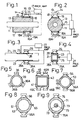
- FIGS. 1 and 2 there is shown an embodiment of the acoustic conductance according to the present invention, which is contributive to a formation of a low gain TCM or, in other words, an active acoustic conductance (which shall be hereinafter referred to simply as "AAC").
- a main duct 11 has an expansion chamber 12 as a passive silencer with an acoustic absorption material 13 inserted therein, and an acoustic conductance 14 is combined with this expansion chamber 12. More concretely, the acoustic conductance 14 is formed by assembling to the passive silencer 12 an acoustic sensor 15, secondary noise source 16 and a processing and amplifying means 17.
- a microphone may be generally employed, while not required to be limited thereto but, for example, an oscillation pick-up or the like may be also employed.
- a loudspeaker is used while not required to be particularly limited thereto. In the event where the loudspeaker is employed, it should be appreciated that such speaker box 19 as shown by imaginary lines is to be provided.
- a plurality of the secondary noise sources 16 are provided around the expansion chamber 12, that is, on an identical circumference along a plane intersecting at right angles the longitudinal axis of the duct 11, and the acoustic sensor 15 is disposed at a position slightly on upstream side with respect to the center of the secondary noise sources 16 and 16A.
- the position where the optimum acoustic conductance is to be constructed should be chosen to be about 1/3 of the length of the expansion chamber 12, while not required to be so limited.
- it is necessary that radiations of the sound waves are producted on both of the upstream and downstream sides in the duct 11.
- the secondary noise sources 16 and 16A having the areas of more than twice as large as that of the cross sectional area of the duct 11.
- a plurality of the secondary noise sources 16 and 16A are provided to the duct 11 on the identical circumference thereof as has been described, and the individual one of the secondary noise sources 16 and 16A may be reduced in the amplitude since the required magnitude of the noise source, i.e., the volume velocity and sound pressure are fixed.
- the acoustic sensor 15 in proximity to the secondary noise sources 16 and 16A, taking advantage of multiplicative effect of a ring formation of the noise sources in which any phase delay in the respective secondary noise sources is reduced, and of the amplitude reduction in each of the plurality of the noise sources.
- the arrangement should preferably be made in such that two of the secondary noise sources 16 and 16A each having almost the same area as the cross sectional area of the duct 11 are provided to oppose each other.
- the two secondary noise sources 16 and 16A it is made possible for the two secondary noise sources 16 and 16A to commonly utilize the signal of the single acoustic sensor 15 by disposing this sensor 15 within a plane of symmetry of the two secondary noise sources 16 and 16A. This will allow the arrangement made simpler than in the event where a plurality of the acoustic sensors 15 are employed, and the disposition of the acoustic sensor 15 with respect to wall surface of the duct 11 becomes also simpler.
- the acoustic sensor 15 is provided to be slightly on upstream side with respect to the secondary noise sources 16 and 16A, it is made possible to attain the phase delay correction as well as a formation of a zone in which reverse phase noise generated by the secondary noise sources 16 and 16A will become a plane wave. For this reason, there can be obtained a distance corresponding to a delay time of the reverse phase sound wave generated from the secondary noise sources 16 and 16A with respect to the sound waves propagated through the duct 11 as caused by the phase delay of the secondary noise sources 16 and 16A.
- the generated sound waves of the secondary noise sources 16 and 16A cannot be deemed to be plane waves at a closely proximate to the secondary noise sources 16 and 16A within the duct 11, there can be formed excellently plane waves at a position on slightly upstream side thereof even when the sound wave signal collected by the acoustic sensor 15 closely proximate to the secondary noise sources 16 and 16A is improper and no oscillation or gain rises.
- a slit-like element 18 to attain an impedence matching between the secondary noise sources 16 and 16A and the duct 11. While the element 18 is not required to be limited in the shape of the slit or its opening rate, it is possible that a slit of an elongated ellipse or the like shape the major axis of which lies in flowing direction of the objective noise to be controlled is optimum, depending on the system of the acoustic absorption to be formed.
- the secondary noise sources 16 and 16A and acoustic sensor 15 as well are protected at their periphery by the acoustic absorption material 13 of a glass wool or the like which also functions as a heat insulating member, so as to isolate them from the fluid within the duct 11, whereby any high frequency component which will be a cause of an oscillation or the like due to the acoustic absorption material 13 can be attenuated and any resonance of the duct 11 can be restrained, that is, no howling is caused to occur so as to stabilize the operation of the acoustic conductance as the AAC.
- the AAC can be optimumly constituted.
- the term "AAC" is to refer to a sensor for collecting the reference signal, which is the one formed by disposing the microphone 15 and secondary noise source 16 substantially at the same position or proximate to each other to have the gain restricted to be relatively low, for example, less than about 20 dB and to have the sensor operated within a range causing no oscillation.
- This is an intention to have the AAC operated as an incomplete reflection plane a stable operation of which is easy to attain, whereas the intention of the conventional TCM is to achieve the complete reflection plane the operation of which is apt to become unstable.
- the noise signals collected by such acoustic sensor 15 as the microphone are subjected to such optimum signal processing as an inversion, so that, as amplified by the amplifier 17, a reverse-phase noise will be radiated out of such secondary noise source 16 as a loudspeaker or the like.
- the acoustic conductance 14 comprising the acoustic sensor 15, secondary noise sources 16 and signal processing and amplifying means 17 is provided to the expansion chamber 12, so that the sound waves propagated from the upstream side in the duct 11 will be reflected or absorbed by this acoustic conductance 14 and acoustic absorption material 13 to be thereby silenced.
- the total area of the oscillating plane of the plurality (two in the drawings) of the secondary noise sources 16 and 16A provided around the expansion chamber 12 is set to be about twice as large or more as the sectional area of the expansion chamber 12, so that the sound waves radiated by the plurality of secondary noise sources 16 and 16A within the expansion chamber 12 will form a ring-like noise source in the space of the expansion chamber 12 in front of the secondary noise sources 16 and 16A and, thus, a sound field of the reverse phase matching with the characteristic impedance of the expansion chamber 12. Further, this matching with the characteristic impedance can be promoted by the slit-like elements 18 disposed in front of the secondary noise sources 16 and 16A.
- the acoustic absorption material 13 of the glass wool or the like disposed in the expansion chamber 12 and functioning also as the heat insulating member is effective to attenuate the high frequency component which can be a cause of the oscillation or the like due to the phase change, so as to restrain any resonance, while functioning as a resistance component in series with the transmission path so as to act to further elevate the silencing effect in the concurrent use with the parallel acoustic conductance.
- the acoustic sensor 15 and secondary noise sources 16 and 16A are not exposed directly to the fluid within the expansion chamber 12 so as to be less influenced by the fuild, any influence of the acoustic arch-fact (windblown noise and so on) can be restricted, and the acoustic sensor and secondary noise source can be prevented from being deteriorated by the heat, dust and mist.
- the acoustic conductance according to the present invention may be applied directly to the duct 11 without providing any expansion chamber, as shown in FIGS. 3 and 4, in which substantially the same constituents as those in the embodiment of FIGS. 1 and 2 are denoted by the same reference numerals as those used in FIGS. 1 and 2 but with a figure "10" added thereto, and, except for the provision of the expansion chamber, substantially the same operation can be preformed.
- FIG. 5 For the arrangement of the acoustic sensor, secondary noise source and acoustic absorption material, it is possible to employ such various arrangements as shown respectively in FIG. 5 where three of the secondary noise sources 36, 36A and 36B are disposed on an identical circumference of the duct 31 of a circuit section as mutually spaces by an angle equally set, in FIG. 6 where four of the secondary noise sources 46, 46A, 46B and 46C are provided on a circumference to be identical with respect to the flow within the duct 41 of a rectangular section, and in FIG. 7 where four of the secondary noise sources 56, 56A, 56B and 56C are provided on a circumference to be identical with respect to the flow within the duct 51 of a circular section. Further arrangements employable will be that as shown in FIG.
- acoustic damper is to mean the one which deforms by itself in accordance with variation in the sound pressure due to the noise and absorbs the energy by means of a resistance accompanying the deformation, and such articles as a corn part of a loudspeaker having a viscosity equivalently to the oscillation, rubber film having the viscosity, or a piston are to be included.
- Example No. Acoustic Conductance Arrangement R Silencing Effect (dB) 1 Duct of 10cm square with 1 loudspeaker 0.75 6 2 Duct of 10cm square with 2 loudspeakers 1.50 8 3 Duct of 75mm diameter with 2 loudspeakers 2.50 18
- “R” is a rate (oscillatory area of secondary noise source/sectional area of duct).
- Example 3 in addition to the use of a circular duct, there was provided an expansion chamber of a sectional area twice as large as that of the duct.
- the silencing effect is improved with an increment in the total oscillatory surface area of the secondary noise sources so long as the sectional area of the duct is constant, that is, with the enlargement of the oscillatory surface area of the secondary noise source in contrast to the sectional area of the duct, and that, as will be clear when Examples 1 and 3 are compared with each other, the silencing effect is remarkably improved by providing the expansion chamber and further enlarging the oscillatory area of the secondary noise sources. In other words, the remarkable silencing effect is to be obtained when the oscillatory area of the secondary noise source is made about twice as large as the sectional area of the duct.
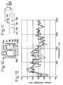
- FIGS. 12 and 13 With the position of microphone as the acoustic sensor varied as shown in FIG. 11, the silencing has been carried out, the comparison of the sound pressure level changes upon which is shown in FIGS. 12 and 13. More concretely, the sound pressure changes caused when the microphone is shifted by 6cm and 10cm onto the upstream side from the center of the speaker, in an arrangement where two loudspeakers as two secondary noise sources are disposed as opposed with respect to the duct formed to be 50mm in diameter, are shown in FIG. 12. As a result, the sound pressure changes in the event where the acoustic sensor is positioned immediately downstream of the secondary noise source will be as represented by dotted-line curve in FIG.
- the changes will be as represented by a broken-line curve when the sensor position is separated 6cm from the secondary noise source, and the changes will be as represented by a chain-line curve in the drawing when the sensor position is further separated 10cm.
- the acoustic sensor is disposed immediately below the secondary noise source. With the acoustic sensor disposed closer to the secondary noise source, it is made unnecessary to render the transmission function complicated. On the other hand, it is not preferable in practice that the acoustic sensor is positioned excessively closer to the secondary noise source.
- a solid-line curve represents a case in which AAC is in OFF state.
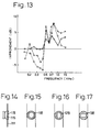
- FIG. 13 the sound pressure level fluctuation upon shifting of the acoustic sensor respectively by 5cm, 10cm and 15cm onto the upstream side from the center of the loudspeaker, with the speaker center denoted by "0", in the arrangement where two of the secondary noise sources are disposed as opposed to each other with respect to the duct of 100mm square.
- the speaker and amplifier different from those used in the example of FIG. 12 have been employed.
- the acoustic sensor or microphone position 0mm Improvement factor upon disposition of the acoustic sensor above the secondary noise source (the acoustic sensor or microphone position 0mm) is presented and, as will be appreciated, the position of the microphone as the acoustic sensor is different in accordance with the form of the duct and the type of the speaker or the like as the secondary noise source. It has been found from FIG. 13 that no remarkable deterioration in the silencing effect and a stable improvement is obtainable in the event where the microphone position is slightly on the upstream side of the secondary noise source, practically 5cm upstream, preferably, in the embodiment of FIG. 11, in contrast to other case where the position is more remote.
- a curve plotted with "o" marks represents a case where the sensor position is 5cm upstream
- a curve with " ⁇ ” denotes 10cm upstream
- a curve with " ⁇ ” marks denote 15cm upstream.
- Examples have been carried out employing a microphone used as the acoustic sensor and loudspeakers respectively having a sound-pressure generating plane substantially equivalent to the sectional area of the duct, resultant relationship of which have been as shown in a following Table II in which the area size of the employed loudspeaker is shown for convenience' sake in the number of the loudspeaker.
- Table II Example No. Number of Loudspeaker Optimum Distance (mm) 4 1 100 5 2 50 6 4 40
- the optimum distance is the one between the microphone as the acoustic sensor and the loudspeaker and at a position of the former where the silencing characteristics are the best.
- the loudspeaker employed was of the sound-pressure generating plane of 100mm (sectional area of 7,850mm2), and the duct was made to be of a diameter 75mm (sectional area of 4,415mm2). While the optimum position of the microphone forming the acoustic sensor varies depending on the shape of the duct and the type of the loudspeaker forming the secondary noise source, the optimum distance is apt to become shorter than the foregoing sensor position.
- the silencing effect can be remarkably improved in the event where such slit 118 at shown in FIGS. 14 and 15 or such slit 128 or 138 as shown in FIG. 16 or 17 is provided at the front face of the secondary noise source.
- the slit formation should not be limited to those shown in FIGS. 14 to 17 but may properly be modified.
- FIG. 18 the silencing improvements caused by the provision of the slit are shown, in which a curve plotted with "o" marks denotes a case of such provision of such circular slit as shown in FIG. 15 with an opening rate of 30% of the oscillatory area of the loudspeaker as the secondary noise source, a curve with " ⁇ " marks denotes a case of such rectangular slit as in FIG.
- FIG. 19 there is shown the silencing amount upon actuation of the AAC in both cases where the acoustic absorption material is provided and is not provided.
- a solid-line curve is of the case where a glass wool is provided as the acoustic absorption material
- a dotted-line curve is of the case of no acoustic absorption material. It is seen from these curves that the howling can hardly be generated in the case where the glass wool is provided as the acoustic absorption material so that the AAC actuation can be stabilized.
- the acoustic conductance according to the present invention also results in an excellent effect when provided at two positions on the duct which communicating with a noise source S as shown in FIG. 20.
- substantially the same constituents as those in the embodiment of FIGS. 1 and 2 are indicated by the same reference numerals as those in FIGS. 1 and 2 but with "190" added, which constituents realizing the same operation.
- FIG. 21 there are shown attenuations in respect of the embodiment of FIG.
- a broken-line curve represents variation in the sound pressure only of the duct
- a chain-line curve represents the sound pressure variation in the duct with the amplifying means of the acoustic conductance made in OFF state
- a solid-line curve denotes the sound pressure variation in the duct with the amplifying means of AAC made ON and the acoustic conductance actuated into ON state.
- FIG. 22 there is provided an arrangement in which the duct 211 is provided with the expansion chamber 212 filled with a glass wool as the acoustic absorption material 213 and the acoustic conductance is disposed at a position downstream of this expansion chamber 212.
- the same constituents as those in the embodiment of FIGS. 1 and 2 are indicated by the same reference numerals as those used in FIGS. 1 and 2 but with "200" added, which constituents realizing also the same operation.
- FIG. 23 there are shown attenuations in respect of the embodiment of FIG.
- a broken-line curve denotes the sound-pressure variation only of the duct
- a chain-line curve shows the sound-pressure variation in an event where the duct is provided only with an expansion chamber
- a solid-line curve represents the sound-pressure variation in the case of the FIG. 22 arrangement in which the duct is provided with both of the expansion chamber and acoustic conductance, and it should be appreciated that the provision of the expansion chamber and acoustic conductance to the duct allows a remarkable silencing effect to be attained.
- FIG. 24 there is provided an arrangement in which the duct 221 is provided with the expansion chamber 222 carrying the acoustic conductance, the expansion chamber 222 is filled with a glass wool as the acoustic absorption material 223, and another acoustic conductance is disposed downstream of the chamber.
- the same constituents as those in the embodiment of FIGS. 1 and 2 are denoted by the same reference numerals as those used in FIGS. 1 and 2 but with "210" added, and the same operation can be realized by these constituents.
- FIG. 25 there are shown attenuations in respect of the embodiment of FIG.
- a broken-line curve denotes the sound-pressure characteristic only of the duct
- a chain-line curve shows the sound-pressure characteristic in an event where the duct is provided only with an expansion chamber
- a solid-line curve represents the sound-pressure characteristic in the case of FIG. 24 where the acoustic conductance is provided to the expansion chamber and to the duct downstream of the chamber, and it is seen that a further excellent silencing effect can be attained with the FIG. 24 arrangement.
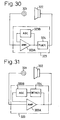
- the silencer in this embodiment according to the present invention includes a signal generating circuit 303 connected to a microphone 301 forming the acoustic sensor and a loudspeaker 302 forming the secondary noise source for generating a signal for driving the loudspeaker 302 on the basis of an output signal of the microphone 301, while this signal processing circuit 303 comprises an inverting amplifier circuit 303A acting simultaneously as an amplifying section and as a phase inverting section, and an AGC circuit 303B which is an amplification degree control section.
- This AGC circuit 303B attains a feedback control of the inverting amplifier circuit 303A so that the amplification degree of the inverting amplifier circuit 303A will be controlled in accordance with output signal level of the microphone 301 provided as input to the circuit 303A, that is, an amplitude voltage, such as shown in FIG. 27. More specifically, in FIG. 27, the amplification degree of the inverting amplifier circuit 303A is made to be of a constant value Go until the amplitude voltage of the output signal of the microphone 301 reaches a first threshold value V1, and, as the amplitude voltage exceeds the first threshold value V1, the amplification degree is decreased at a constant decrement in accordance with the increment in the amplitude voltage. Further, as the amplitude voltage exceeds a second threshold value V2, the decrement of the amplification degree is inlarged.
- the amplification degree Go in the event where the amplitude voltage of the microphone output signal is below the first threshold voltage V1 is so set as to be of a level of causing no howling, the exceeding of the microphone output signal over the first threshold voltage V1 and showing a tendency of the howling to take place will cause the amplification degree to be lowered and the howling occurrence can be thereby restrained.
- the amplitude voltage further exceeds the second threshold value V2
- the decrement of the amplification degree is further enlarged and the howling occurrence can be reliably prevented.
- a filter circuit 314 acting as a frequency characteristics control section is inserted between the inverting amplifier circuit 313A and the loudspeaker 312, in order to correct the frequency characteristics in a loop of the microphone 311 ⁇ signal processing circuit 313 ⁇ loudspeaker 312 ⁇ microphone 311.
- a low-pass filter having such frequency response as shown in FIG. 29 may be employed.
- the filter circuit 314 having such characteristic With the use of such filter circuit 314 having such characteristic, the amplification degree of the high frequency component in the above loop can be restrained. Since the high frequency component has a higher possibility of causing the howling to occur, in general, the use of the filter circuit 314 having such characteristic allows the effect of restraining the howling to be increased. That is, for the low frequency component, it is possible to render the amplification degree of the above loop to be larger, so that the silencing effect with respect to the noises of a larger sound pressure level of the low frequency component can be elevated.
- FIG. 28 While the embodiment of FIG. 28 has been shown to insert the filter circuit 314 between the inverting amplifier circuit 313A and the loudspeaker 312, this filter circuit 314 may be inserted as connected either to an output part or an input part of the AGC circuit 313B. Further, the frequency response of the filter circuit 314 is not always to be limited to such characteristics as in FIG. 29 but may properly be set depending on the object.
- phase fluctuation circuit 324 acting as a phase fluctuating section which provides a fluctuation to the phase of the output signal of the microphone 321.
- the phase fluctuation circuit 324 is to cause the phase of the output signal of the microphone 321 to be fluctuated with respect to the signal of the phase inverted at the inverting amplifier circuit 323A to be different 180 degrees.
- phase fluctuation circuit 324 may be constituted by means of, for example, a delay circuit and switching element, so that ON/OFF operation of the switching element at indefinite intervals will cause a signal delay by means of the delay circuit to occur at the indefinite intervals.
- the phase relationship between the output signal of the microphone 321 and the driving signal for the loudspeaker 322 and even becoming to satisfy the conditions for causing the howling to occur at a specific time will be fluctuated immediately thereafter. Consequently, the howling generating conditions are not satisfied, and the howling generation can be restrained. In other words, the howling generation which is apt to occur when the amplification degree is made larger can be effectively restrained, even when the amplification degree in the above loop is set to be large so as to elevate the silencing effect.
- phase fluctuation circuit 324 is shown to be inserted between the inverting amplifier circuit 323A and the loudspeaker 322, by the way, it is also possible to insert this phase fluctuation circuit 324 either in the output section or the input section of the AGC circuit 323B.
- a frequency detecting circuit 334 capable of detecting the howling is inserted in the input section of the AGC circuit 333B.
- the AGC circuit 333B acting as an amplification control section is controlled upon detection by the frequency detecting circuit 334 of a signal of an oscillation (single frequency or the like), and the amplification degree in the loop of the microphone 331 ⁇ signal processing circuit 333 ⁇ loudspeaker 332 ⁇ microphone 331 is lowered.
- the one which can change over the amplification degree of the inverting amplifier circuit 333A at two stages before and after the howling generation is to be employed.
- a PLL circuit or the like may be employed for the frequency detecting circuit 334. Since the howling is to normally oscillate at a single frequency, the howling generation can be exactly detected by the frequency detecting circuit 334. Upon occurrence of the howling, on the other hand, the circuit 334 lowers effectively the amplification degree of the foregoing loop for restraining the howling. With this arrangement, the howling even generated can be immediately stopped and the amplification degree at the foregoing loop can be effectively increased, so that the silencing effect can be increased.
- an amplification fluctuating circuit 344 is employed in place of the AGC circuit, and this amplification fluctuating circuit 344 is constituted to vary the amplification degree of the inverting amplifier circuit 343A with the lapse of time in such manner as shown in FIG. 33. That is, when the amplification degree of the inverting amplifier circuit 343A upon occurrence of the howling is made Gs, the amplification fluctuating circuit 344 causes the amplification degree Gs in a predetermined range (Ga ⁇ Gs ⁇ Gb) with the lapse of time, so that the amplification degree will be controllably varied periodically in such a saw-tooth wave form as shown in FIG. 33 with the lapse of time.
- the amplification degree even when the same in a loop of the microphone 341 ⁇ signal processing circuit 343 ⁇ loudspeaker 342 ⁇ microphone 341 is made large to cause the howling to occur will be lowered at a next moment so as not to allow the howling conditions to be satisfied, and the howling occurrence can be restrained.
- intermittent it is possible to provide to the above loop a larger amplification degree Gb than the amplification degree Gs which allows the howling to occur, so that the silencing amount can be increased.
- the silencing amount varied in response to the variation in the amplification degree causes the objective sound waves of the silencing to involve a phenomenon of irregularity
- a setting of the amplification fluctuating circuit 344 for variation by 1/f fluctuation of the sound wave after the silencing will be able to alleviate the irregularity phenomenon.
- phase inversion is shown to be realized by the inverting amplifier circuit
- the phase inversion may be attained by connecting the circuit to the loudspeaker as the secondary noise source in reverse polarity.
- analog signal is employed for internal precessing at the signal processing circuit, it may be possible to employ a D/A processor in place of the signal processing circuit to have the internal processing carried out by a digital signal.
Landscapes
- Engineering & Computer Science (AREA)
- Physics & Mathematics (AREA)
- Acoustics & Sound (AREA)
- Multimedia (AREA)
- General Engineering & Computer Science (AREA)
- Mechanical Engineering (AREA)
- Soundproofing, Sound Blocking, And Sound Damping (AREA)
- Exhaust Silencers (AREA)
Applications Claiming Priority (4)
| Application Number | Priority Date | Filing Date | Title |
|---|---|---|---|
| JP291892/91 | 1990-10-31 | ||
| JP2291892A JP2975966B2 (ja) | 1990-10-31 | 1990-10-31 | 音響コンダクタンス |
| JP3058805A JPH05210391A (ja) | 1991-03-22 | 1991-03-22 | 消音装置 |
| JP58805/91 | 1991-03-22 |
Publications (2)
| Publication Number | Publication Date |
|---|---|
| EP0483921A1 true EP0483921A1 (fr) | 1992-05-06 |
| EP0483921B1 EP0483921B1 (fr) | 1995-08-16 |
Family
ID=26399808
Family Applications (1)
| Application Number | Title | Priority Date | Filing Date |
|---|---|---|---|
| EP91202781A Expired - Lifetime EP0483921B1 (fr) | 1990-10-31 | 1991-10-28 | Conductance acoustique dans un système de conduit |
Country Status (3)
| Country | Link |
|---|---|
| US (1) | US5257316A (fr) |
| EP (1) | EP0483921B1 (fr) |
| DE (1) | DE69112172T2 (fr) |
Cited By (6)
| Publication number | Priority date | Publication date | Assignee | Title |
|---|---|---|---|---|
| EP0592693A4 (en) * | 1992-05-01 | 1994-09-28 | Fujitsu Ten Ltd | Noise control device |
| WO1995019075A3 (fr) * | 1993-12-30 | 1995-07-27 | Bolt Beranek & Newman | Silencieux actif |
| US5822439A (en) * | 1992-05-01 | 1998-10-13 | Fujitsu Ten Limited | Noise control device |
| US6160892A (en) * | 1993-12-30 | 2000-12-12 | Bbn Corporation | Active muffler |
| EP1215652A3 (fr) * | 2000-12-12 | 2005-05-04 | Deutsche Montan Technologie GmbH | Dispositif anti-bruit multicanaux |
| EP2444605A1 (fr) * | 2010-10-20 | 2012-04-25 | J. Eberspächer GmbH & Co. KG | Amortisseur de bruit |
Families Citing this family (10)
| Publication number | Priority date | Publication date | Assignee | Title |
|---|---|---|---|---|
| US5319165A (en) * | 1990-04-25 | 1994-06-07 | Ford Motor Company | Dual bandpass secondary source |
| US5323466A (en) * | 1990-04-25 | 1994-06-21 | Ford Motor Company | Tandem transducer magnet structure |
| JP3340496B2 (ja) * | 1993-03-09 | 2002-11-05 | 富士通株式会社 | アクティブ騒音制御システムの伝達特性の推定方法 |
| CN1064158C (zh) * | 1993-07-07 | 2001-04-04 | 莱斯特里兹股份有限公司&废气处理技术公司 | 有源消声器 |
| US6343127B1 (en) | 1995-09-25 | 2002-01-29 | Lord Corporation | Active noise control system for closed spaces such as aircraft cabin |
| US5571242A (en) * | 1995-12-26 | 1996-11-05 | General Motors Corporation | Engine airflow system and method |
| US7113607B1 (en) * | 1998-09-03 | 2006-09-26 | Mullins Joe H | Low frequency feedback controlled audio system |
| DE102004040421A1 (de) * | 2004-08-19 | 2006-03-09 | J. Eberspächer GmbH & Co. KG | Aktiver Abgasschalldämpfer |
| DE102007032600A1 (de) * | 2007-07-11 | 2009-01-15 | Deutsches Zentrum für Luft- und Raumfahrt e.V. | Vorrichtung und Verfahren zur Verbesserung der Dämpfung von akustischen Wellen |
| CN115750978A (zh) * | 2021-09-02 | 2023-03-07 | 中国石油天然气股份有限公司 | 一种适用于输气汇管的有源降噪系统 |
Citations (3)
| Publication number | Priority date | Publication date | Assignee | Title |
|---|---|---|---|---|
| WO1983000580A1 (fr) * | 1981-08-11 | 1983-02-17 | Chaplin, George, Brian, Barrie | Procede et dispositif d'attenuation active des basses frequences |
| GB2142091A (en) * | 1983-06-23 | 1985-01-09 | Nat Res Dev | Attenuation of sound waves |
| EP0227372A2 (fr) * | 1985-12-18 | 1987-07-01 | Nelson Industries, Inc. | Amortisseur de son actif hybride |
Family Cites Families (6)
| Publication number | Priority date | Publication date | Assignee | Title |
|---|---|---|---|---|
| US2840178A (en) * | 1954-01-20 | 1958-06-24 | Tesla Np | Device for the reproduction of sound |
| US4473906A (en) * | 1980-12-05 | 1984-09-25 | Lord Corporation | Active acoustic attenuator |
| GB8317086D0 (en) * | 1983-06-23 | 1983-07-27 | Swinbanks M A | Attenuation of sound waves |
| JPH01245795A (ja) * | 1988-03-28 | 1989-09-29 | Daikin Ind Ltd | 電子消音装置 |
| US4965837A (en) * | 1988-12-28 | 1990-10-23 | Pioneer Electronic Corporation | Environmentally resistant loudspeaker |
| JP3394770B2 (ja) * | 1989-09-13 | 2003-04-07 | 卓支 森 | 消音システム |
-
1991
- 1991-10-24 US US07/782,098 patent/US5257316A/en not_active Expired - Lifetime
- 1991-10-28 DE DE69112172T patent/DE69112172T2/de not_active Expired - Lifetime
- 1991-10-28 EP EP91202781A patent/EP0483921B1/fr not_active Expired - Lifetime
Patent Citations (3)
| Publication number | Priority date | Publication date | Assignee | Title |
|---|---|---|---|---|
| WO1983000580A1 (fr) * | 1981-08-11 | 1983-02-17 | Chaplin, George, Brian, Barrie | Procede et dispositif d'attenuation active des basses frequences |
| GB2142091A (en) * | 1983-06-23 | 1985-01-09 | Nat Res Dev | Attenuation of sound waves |
| EP0227372A2 (fr) * | 1985-12-18 | 1987-07-01 | Nelson Industries, Inc. | Amortisseur de son actif hybride |
Cited By (7)
| Publication number | Priority date | Publication date | Assignee | Title |
|---|---|---|---|---|
| EP0592693A4 (en) * | 1992-05-01 | 1994-09-28 | Fujitsu Ten Ltd | Noise control device |
| US5822439A (en) * | 1992-05-01 | 1998-10-13 | Fujitsu Ten Limited | Noise control device |
| WO1995019075A3 (fr) * | 1993-12-30 | 1995-07-27 | Bolt Beranek & Newman | Silencieux actif |
| US6160892A (en) * | 1993-12-30 | 2000-12-12 | Bbn Corporation | Active muffler |
| EP1215652A3 (fr) * | 2000-12-12 | 2005-05-04 | Deutsche Montan Technologie GmbH | Dispositif anti-bruit multicanaux |
| EP2444605A1 (fr) * | 2010-10-20 | 2012-04-25 | J. Eberspächer GmbH & Co. KG | Amortisseur de bruit |
| US8434590B2 (en) | 2010-10-20 | 2013-05-07 | J. Eberspaecher Gmbh & Co., Kg | Muffler |
Also Published As
| Publication number | Publication date |
|---|---|
| DE69112172D1 (de) | 1995-09-21 |
| EP0483921B1 (fr) | 1995-08-16 |
| US5257316A (en) | 1993-10-26 |
| DE69112172T2 (de) | 1996-03-28 |
Similar Documents
| Publication | Publication Date | Title |
|---|---|---|
| EP0483921B1 (fr) | Conductance acoustique dans un système de conduit | |
| US6963647B1 (en) | Controlled acoustic waveguide for soundproofing | |
| US4527282A (en) | Method and apparatus for low frequency active attenuation | |
| CN1387386B (zh) | 电声波导系统以及操作声音波导管的方法 | |
| US4589133A (en) | Attenuation of sound waves | |
| AU719258B2 (en) | Active sound attenuation device to be arranged inside a duct, particularly for the sound insulation of a ventilating and/or air conditioning system | |
| US6385321B1 (en) | Reactive sound absorber | |
| US5347585A (en) | Sound attenuating system | |
| US5414230A (en) | Silencer arrangement for combustion engines | |
| US20210105557A1 (en) | Horn loudspeakers | |
| JPH10333686A (ja) | 消音器 | |
| JP2880050B2 (ja) | 消音装置 | |
| US11812219B2 (en) | Asymmetry sound absorbing system via shunted speakers | |
| JPH05280115A (ja) | 遮音パネル | |
| JP3394770B2 (ja) | 消音システム | |
| WO1993005282A1 (fr) | Pot d'echappement | |
| EP0589516A2 (fr) | Dispositif silencieux pour des moteurs à combustion | |
| JPS6248911A (ja) | 能動的消音装置 | |
| JPH05210391A (ja) | 消音装置 | |
| JP3332162B2 (ja) | アクティブ消音装置 | |
| JP3148969B2 (ja) | 消音装置 | |
| JPH03231599A (ja) | 能動制御型消音装置 | |
| CA1298793C (fr) | Systeme d'insonorisation active | |
| JPS6126674B2 (fr) | ||
| SU953233A1 (ru) | Глушитель шума |
Legal Events
| Date | Code | Title | Description |
|---|---|---|---|
| PUAI | Public reference made under article 153(3) epc to a published international application that has entered the european phase |
Free format text: ORIGINAL CODE: 0009012 |
|
| 17P | Request for examination filed |
Effective date: 19920224 |
|
| AK | Designated contracting states |
Kind code of ref document: A1 Designated state(s): DE FR GB IT |
|
| 17Q | First examination report despatched |
Effective date: 19930426 |
|
| GRAA | (expected) grant |
Free format text: ORIGINAL CODE: 0009210 |
|
| AK | Designated contracting states |
Kind code of ref document: B1 Designated state(s): DE FR GB IT |
|
| REF | Corresponds to: |
Ref document number: 69112172 Country of ref document: DE Date of ref document: 19950921 |
|
| ITF | It: translation for a ep patent filed | ||
| ET | Fr: translation filed | ||
| PLBE | No opposition filed within time limit |
Free format text: ORIGINAL CODE: 0009261 |
|
| STAA | Information on the status of an ep patent application or granted ep patent |
Free format text: STATUS: NO OPPOSITION FILED WITHIN TIME LIMIT |
|
| 26N | No opposition filed | ||
| REG | Reference to a national code |
Ref country code: GB Ref legal event code: IF02 |
|
| PGFP | Annual fee paid to national office [announced via postgrant information from national office to epo] |
Ref country code: FR Payment date: 20101020 Year of fee payment: 20 |
|
| PGFP | Annual fee paid to national office [announced via postgrant information from national office to epo] |
Ref country code: DE Payment date: 20101020 Year of fee payment: 20 |
|
| PGFP | Annual fee paid to national office [announced via postgrant information from national office to epo] |
Ref country code: GB Payment date: 20101027 Year of fee payment: 20 Ref country code: IT Payment date: 20101022 Year of fee payment: 20 |
|
| REG | Reference to a national code |
Ref country code: DE Ref legal event code: R071 Ref document number: 69112172 Country of ref document: DE |
|
| REG | Reference to a national code |
Ref country code: DE Ref legal event code: R071 Ref document number: 69112172 Country of ref document: DE |
|
| REG | Reference to a national code |
Ref country code: GB Ref legal event code: PE20 Expiry date: 20111027 |
|
| PG25 | Lapsed in a contracting state [announced via postgrant information from national office to epo] |
Ref country code: GB Free format text: LAPSE BECAUSE OF EXPIRATION OF PROTECTION Effective date: 20111027 |
|
| PG25 | Lapsed in a contracting state [announced via postgrant information from national office to epo] |
Ref country code: DE Free format text: LAPSE BECAUSE OF EXPIRATION OF PROTECTION Effective date: 20111029 |