EP0483966A2 - Procédé et appareil pour l'inspection d'un article transparent ou translucide telle qu'une bouteille - Google Patents
Procédé et appareil pour l'inspection d'un article transparent ou translucide telle qu'une bouteille Download PDFInfo
- Publication number
- EP0483966A2 EP0483966A2 EP91308614A EP91308614A EP0483966A2 EP 0483966 A2 EP0483966 A2 EP 0483966A2 EP 91308614 A EP91308614 A EP 91308614A EP 91308614 A EP91308614 A EP 91308614A EP 0483966 A2 EP0483966 A2 EP 0483966A2
- Authority
- EP
- European Patent Office
- Prior art keywords
- picture element
- inspection
- bottle
- element data
- differences
- Prior art date
- Legal status (The legal status is an assumption and is not a legal conclusion. Google has not performed a legal analysis and makes no representation as to the accuracy of the status listed.)
- Granted
Links
Images


Classifications
-
- G—PHYSICS
- G01—MEASURING; TESTING
- G01N—INVESTIGATING OR ANALYSING MATERIALS BY DETERMINING THEIR CHEMICAL OR PHYSICAL PROPERTIES
- G01N21/00—Investigating or analysing materials by the use of optical means, i.e. using sub-millimetre waves, infrared, visible or ultraviolet light
- G01N21/84—Systems specially adapted for particular applications
- G01N21/88—Investigating the presence of flaws or contamination
- G01N21/90—Investigating the presence of flaws or contamination in a container or its contents
- G01N21/9045—Inspection of ornamented or stippled container walls
-
- G—PHYSICS
- G01—MEASURING; TESTING
- G01N—INVESTIGATING OR ANALYSING MATERIALS BY DETERMINING THEIR CHEMICAL OR PHYSICAL PROPERTIES
- G01N21/00—Investigating or analysing materials by the use of optical means, i.e. using sub-millimetre waves, infrared, visible or ultraviolet light
- G01N21/84—Systems specially adapted for particular applications
- G01N21/88—Investigating the presence of flaws or contamination
- G01N21/8851—Scan or image signal processing specially adapted therefor, e.g. for scan signal adjustment, for detecting different kinds of defects, for compensating for structures, markings, edges
-
- G—PHYSICS
- G06—COMPUTING OR CALCULATING; COUNTING
- G06T—IMAGE DATA PROCESSING OR GENERATION, IN GENERAL
- G06T7/00—Image analysis
- G06T7/0002—Inspection of images, e.g. flaw detection
- G06T7/0004—Industrial image inspection
- G06T7/0006—Industrial image inspection using a design-rule based approach
-
- G—PHYSICS
- G06—COMPUTING OR CALCULATING; COUNTING
- G06T—IMAGE DATA PROCESSING OR GENERATION, IN GENERAL
- G06T7/00—Image analysis
- G06T7/10—Segmentation; Edge detection
- G06T7/136—Segmentation; Edge detection involving thresholding
-
- G—PHYSICS
- G01—MEASURING; TESTING
- G01N—INVESTIGATING OR ANALYSING MATERIALS BY DETERMINING THEIR CHEMICAL OR PHYSICAL PROPERTIES
- G01N21/00—Investigating or analysing materials by the use of optical means, i.e. using sub-millimetre waves, infrared, visible or ultraviolet light
- G01N21/84—Systems specially adapted for particular applications
- G01N21/88—Investigating the presence of flaws or contamination
- G01N21/8851—Scan or image signal processing specially adapted therefor, e.g. for scan signal adjustment, for detecting different kinds of defects, for compensating for structures, markings, edges
- G01N2021/8887—Scan or image signal processing specially adapted therefor, e.g. for scan signal adjustment, for detecting different kinds of defects, for compensating for structures, markings, edges based on image processing techniques
-
- G—PHYSICS
- G06—COMPUTING OR CALCULATING; COUNTING
- G06T—IMAGE DATA PROCESSING OR GENERATION, IN GENERAL
- G06T2207/00—Indexing scheme for image analysis or image enhancement
- G06T2207/30—Subject of image; Context of image processing
- G06T2207/30108—Industrial image inspection
- G06T2207/30164—Workpiece; Machine component
Definitions
- This invention relates to a method of and an apparatus for inspecting a bottle or the like using an optical device, to determine the presence or absence of a defect by electronic processing.
- light is irradiated in an inverted conical ring shape upon a circumferential side wall of a bottle for inspection from above from a light projecting section such that it may be introduced toward a bottom face of the bottle so as to reach a corner material portion of the bottom through the material of the side wall of the bottle, and reflected light which is reflected, where there is a split in the corner material portion, from such split is introduced into a single photoelectric transducer element to detect such split.
- the optical system is complicated in construction, and besides, since reflected light is detected only by means of the single photoelectric transducer element, if the angle of light reflected from a check is only a little different from a specified angular range, such reflected light will not be introduced into the photoelectric transducer element, and consequently, the presence or absence of a defect cannot be detected accurately.
- various design patterns are commonly formed on the bottom faces of bottles, and the amount of reflected light varies to a great extent depending upon such design pattern. Accordingly, it is impossible to detect a check of a bottle only from a variation in amount of light when the bottle has a design pattern thereon.
- Two sets of signals obtained at a first rotational position of the bottle and a second rotational position of the bottle after rotation of the bottle from the first rotational position are compared with each other, and the presence or absence of a defect is determined in accordance with the result of such comparison.
- a method of inspecting an object for inspection such as a bottle or the like being rotated or moved at a predetermined speed to detect defects in the object, which comprises the steps of irradiating light upon an inspection area of the object being rotated or moved, photographing reflected light from the inspection area of the object by means of a two-dimensional camera which includes solid-state image pickup elements, fetching picture element data for a first frame at a first point of time from the two-dimensional camera and storing the data into a memory, fetching picture element data for a second frame at a second point of time after a fixed interval of time after the first point of time, calculating differences of the picture element data for the second from from the picture element data for the first frame from the memory, binary digitizing the differences with reference to a predetermined brightness threshold level, counting the number of those of the differences which have one of two binary values, and comparing the count number with a predetermined number to determine presence or absence of a defect in the object for inspection.
- the object for inspection is, for example, a bottle and has a check as a defect
- the direction of reflected light from the check is instantaneously changed to a great extent by rotation or movement of the bottle, even if picture element data originating from such reflected light are fetched at a certain point T1 of time from the two-dimensional camera as a picture element at a certain position, picture element data originating from reflected light of the check are not fetched at another point T2 of time after the predetermined interval of time.
- picture element data are fetched at both of the points T1 and T2 of time.
- the speed of rotation or movement of the object changes, then also the direction of reflected light from such check is changed and the amount of incidence light to the two-dimensional camera is changed.
- the fixed interval of time between frames at which picture element data are to be fetched and the brightness threshold level for binary digitization are adjusted in response to the speed of the object for inspection in order to improve the accuracy in detection. Consequently, when data for each one frame from the two-dimensional camera are to be fetched at a high speed, the number of frames to be thinned out is adjusted in response to the speed of rotation or movement of the object.
- the number of those of the differences which have one of two binary values is counted for each of a plurality of window areas included in a photographing area of the two-dimensional camera in order to except such picture elements originating from a design pattern formed on the object for inspection.
- the two-dimensional camera can thus detect presence or absence of a defect of the object for inspection with a high degree of accuracy for the plurality of locations of the object without detecting a design pattern or the like as a defect in error.
- an apparatus for inspecting an object for inspection such as a bottle or the like being rotated or moved at a predetermined speed by a handling machine to detect a defect of the object
- a light projector for irradiating light upon an inspection area of an object for inspection being rotated or moved
- a two-dimensional CCD (charge-coupled device) camera for photographing reflected light from the object only for a fixed area
- a camera controller for successively fetching picture element data produced from the two-dimensional CCD camera for each one frame after each predetermined interval of time and storing the thus fetched picture element data therein
- a difference calculating section for calculating differences between the picture element data thus fetched for different frames
- a binary digitizing section for binary digitizing the thus calculated differences with reference to a predetermined brightness threshold level
- a counter for counting the number of those of the differences which have one of two binary values
- a main controller for adjusting the predetermined interval of time for the camera controller and the predetermined bright threshold level for the
- the apparatus may further comprise means for causing the counter to count a number of those of the differences which have one of two binary values only for one or ones of a plurality of window areas included in a photographing area of the two-dimensional CCD camera which is or are designated by the main controller.
- the apparatus further comprises a monitoring display apparatus for reproducing and displaying thereon data for a frame fetched by the camera controller so that setting for inspection can be performed appropriately and readily while a condition of a defect is being observed.
- a monitoring display apparatus for reproducing and displaying thereon data for a frame fetched by the camera controller so that setting for inspection can be performed appropriately and readily while a condition of a defect is being observed.
- FIG. 2 there is illustrated a defect detecting method to which the present invention is applied.
- a transparent or translucent bottle 1 which is an object for inspection is transported along a guide rail 2 to an inspection window 4 (FIG. 3) formed in a table 3.
- an inspection window 4 (FIG. 3) formed in a table 3.
- the light projector 6 is connected to a halogen light source 8 by way of an optical fiber 7 and projects light from the halogen light source 8 in a little obliquely downward direction toward a bottom portion of the bottle 1.
- a two-dimensional CCD camera 9 is installed such that an optical axis thereof makes a predetermined angle with respect to an optical axis of the light projector 6.
- the two-dimensional CCD camera 9 photographs, through the inspection window 4 of the table 3, a portion of the bottom of the bottle 1 illuminated with light from the light projector 6.
- FIG. 4 there is shown, in a rectangular screen, a picture image for one frame photographed by the two-dimensional CCD camera 9 at a point T 1 of time.
- the two-dimensional CCD camera 9 photographs only part of the bottom of the bottle 1, and a white picture image 10 originates from reflected light from a check formed in a circumferential edge portion of the bottom of the bottle 1 and is high in brightness.
- Another small white picture image 11 originates from disturbance light from some portion other than the check (for example, reflected light from a portion of the table 3).
- a plurality of regularly spaced black picture images 12 originate from projected portions which may be provided on the bottom of the bottle 1 in order to indicate a model number and so forth of the bottle 1 in a code system.
- Another black picture image 13 originates from a design pattern provided on the bottom face of the bottle 1. Since the direction of reflected light from the check is instantaneously changed to a great extent if the bottle 1 is rotated only a little as described hereinabove, the picture image 10 originating from the check moves, at another point T 2 of time after a short predetermined interval of time after the point T 1 of time mentioned hereinabove, to a great extent as indicated by a broken line in the photographing screen of the two-dimensional CCD camera 9 while the picture image 11 originating from disturbance light from any other portion than the check little moves.
- a picture image processing unit 14 is connected to the two-dimensional CCD camera 9. Picture element data produced from the camera 9 are accepted by the picture element processing unit 14 for each one frame and stored into a memory(not shown)of the picture element processing unit 14. The picture element data thus stored in the memory are thereafter processed as hereinafter described.
- a monitoring television set 15 in the form of a cathode ray tube is connected to the picture image processing unit 14 so that a picture image accepted into the picture image processing unit 14 can be displayed at any time on the television set 15.
- the picture image processing unit 14 has a general construction as shown in FIG. 1.
- a large number of picture element data for one frame obtained from the two-dimensional CCD camera 9 are inputted to a camera controller 16 for each one frame.
- picture element data are successively inputted to the camera controller 16, for example, for a total of 115 frames for one full rotation of the bottle 1 at a time interval of a fixed short time t and stored into a memory not shown therein.
- Picture element data for one frame designated by a main controller 19 are outputted from the camera controller 16 and stored once into a buffer memory 17, and differences of different picture element data for a next designated one frame which are inputted after an interval of time of t x k after the certain point of time are calculated at a difference calculating section 18.
- k is a thinning out value and is set in such a manner as hereinafter described by the main controller 19 which has a CPU (central processing unit) not shown therein.
- the reason why differences between picture image data for two frames obtained at different times different by t x k are calculated is that it is intended to extract only such picture image 10 as shown in FIG. 4 which originates from a check of a bottle.
- a picture element output of the two-dimensional CCD camera 9 is taken in the form of an analog waveform along a straight line A-A of the rectangular photographing screen at different rotational positions of the bottle 1 and is shown in waveform diagram in a corresponding relationship with the picture image below the photographing screen.
- the waveform presents a high level or peak only at a portion thereof which corresponds to the picture image 11 originating from disturbance light.
- the picture image 11 originating from disturbance light moves little, but the picture image 10 originating from the check has been moved to and is now at a broken line position, and consequently, the analog waveform then exhibits high levels or peaks at a portion thereof which corresponds to the picture image 11 originating from disturbance light and another portion which corresponds to the picture image 10 originating from the check.
- the peak at the portion corresponding to the picture image 10 originating from the check remains, but the other peak at the portion corresponding to the picture image 11 originating from disturbance light is cancelled.
- the reason why differences are taken between picture image data for two frames obtained at different times different by the interval of time t x k is that, when the bottle 1 is rotated at a very high speed, such calculation of differences between each successive ones of the total of 115 frames for one full rotation of the bottle 1 may not be performed, and in order to eliminate such a possible circumstance, different frames different more than one frame distance are selected for such calculation of differences.
- the value of the thinning out value k is thus determined in response to a speed of rotation of the bottle 1 such that, while the speed of rotation of the bottle 1 rises, the interval of time t x k may not be varied significantly.
- the differences in picture element data calculated at the difference calculating section 18 are then binary digitized for each picture element by a binary digitizing section 20 with reference to a certain level of brightness or threshold level.
- a certain brightness level is determined as a reference or threshold level
- picture element data are divided into two groups of white and black such that, if the picture element data are equal to or higher than the certain brightness threshold level, then they are determined as white (1 in binary digital value), but if they are lower than the predetermined brightness threshold level, then they are determined as black (0 in binary digital value).
- Such binary digitization is performed successively for all of picture elements for one frame.
- the level H serving as the reference level for binary digitization is automatically adjusted in response to a speed of rotation of the bottle 1 by the main controller 19. The reason is that, when the speed of rotation of the bottle 1 is high, the amount of incidence light to the two-dimensional CCD camera for photographing one frame and hence output levels of individual solid-state image pickup elements are low correspondingly.
- the rectangular photographing screen of FIG. 4 is divided into first to n-th window areas W i , W 2 , ... and W n where the picture image 10 of a check is apt to appear, and a number of those of picture elements which are determined as white by binary digitization (defect picture elements) is counted individually for each of the window areas Wi, W 2 , ... and W n .
- data representative positions of individual picture elements in a window area are stored into a window memory 21 in accordance with an instruction from the main controller 19, and only those of binary data of white from the binary digitizing section 20 which belong to the window area pass through a gate circuit 22 and are thus counted by a counter 23. Consequently, such count value of the counter 23 represents a number of defect picture elements in the window area, and in case the count value is higher than a fixed level, the main controller 19 determines that there is a check in the bottle 1 and outputs, by way of an interface 24, an excluding signal to the handling machine 30 to exclude such defective bottle 1 from the transporting line. The main controller 19 further controls an inspection result display unit 25 to display a number of such defective bottles, a defective location and so forth thereon.
- Picture element data for each one frame fetched into the camera controller 16 are stored in digital amount into a display memory 26 in a predetermined period set by the main controller 19 and are then converted into a video signal by a digital/video signal converting section 27 so that they are reproduced by and displayed on the monitoring television set 15.
- Initial set values and so forth necessary for inspection are inputted in prior to the main controller 19 by way of an interface 29 from a keyboard 28 while a reproduced image on the television set 15 is being observed by an operator.
- An inspection timing signal, a bottle presence signal representing that a bottle is present at a predetermined inspection position, a speed signal representing a speed of rotation of such bottle and so forth are inputted from a handling machine 30 to the main controller 19.
- the thinning out value k and the reference level H for binary digitization described above are adjusted in accordance with the thus inputted speed signal.
- the handling machine 30 performs various operations including transporting a bottle 1 and rotating the bottle 1 at the inspection position by means of the drive disk 5 as described above.
- a speed of rotation of the bottle 1 may be measured by counting a number of inspection timing signals received by the main controller 19 for a unit period of time.
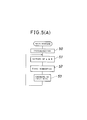
- FIGS. 5(A) to 5(C) Operation of the main controller 19 is illustrated in FIGS. 5(A) to 5(C).
- various initializing operations are executed first at step 50, and then at step 51, such thinning out value k and reference level H for binary digitization as described above are set in accordance with a speed signal from the handling machine 30 or a speed measured from inspection timing signals.
- step 52 a first subroutine shown in FIG. 5(B) is executed, and then at step 53, conditions of input keys of the keyboard 28 are checked, whereafter the control sequence returns to step 51.
- step 55 When the first subroutine shown in FIG. 5(B) is entered, it is judged first at step 55 whether or not there is an inspection timing signal, and if there is no inspection timing signal, then conditions of the input keys of the keyboard 28 are checked at step 56, whereafter the control sequence returns to step 55 to repeat a similar sequence of operations. On the contrary if there is an inspection timing signal at step 55, then the control sequence advances to step 57, at which counting of a counter for measuring an inspection time is started, and then to step 58, at which it is judged whether or not there is a bottle presence signal, in short, whether or not a bottle 1 is present at the inspection position.
- a bottle 1 is present, then all rejection flags are reset at step 64, and then a skip flag is set at step 65.
- the skip flag is provided so that picture element data for a first one frame received at first from the camera controller 16 shown in FIG. 1 may be stored into the buffer memory 17. Thus, the skip flag is set in the first control cycle. Subsequently, a second subroutine shown in FIG. 5(C) is executed.
- step 72 it is judged first at step 72 whether or not the skip flag is in a set state. Since the skip flag is in a set state in the first control cycle, the control sequence advances to step 77, at which the counter 23 of FIG. 1 is reset, and then to step 78, at which the skip flag is reset, whereafter the control sequence returns to the first subroutine of FIG. 5(B).
- step 73 at which a number of defect picture elements in the first window area W 1 is counted by the counter 23 as described hereinabove, and then to step 74, at which the count value is compared with a fixed excluding level set for the first window area Wi. Then, a judgment for allowance or rejection for the window area W 1 is made at step 75 in accordance with a result of such comparison. In case the judgment is rejection, a rejection flag is set for the window area W 1 at step 76, but in the case of allowance, the control sequence advances to a step for the second window area W 2 skipping the step 76.
- step 67 presence or absence of an inspection timing signal is determined at step 67, and if there is an inspection timing signal, then conditions of the input keys are checked at step 68, whereafter the control sequence returns to step 67. If there is no inspection timing signal at step 67, then the main controller 19 checks all of the rejection flags for the windows W 1 to W n and determines, when all of the rejection flags are not in a set state, that the bottle 1 is allowable, but determines, when at least one of the rejection flags is in a set state, that a check is present at a corresponding window and accordingly the bottle 1 is to be rejected. Then, a result of the determination is outputted to the handling machine 30 at step 70.
- the main controller 19 outputs, by way of the interface 24, an excluding signal to the handling machine 30 to exclude such defective bottle 1 from the transporting line. Then, the inspection time measuring counter is stopped at step 61, and then the thinning out number k and the reference level H for binary digitization are newly set at step 62, whereafter the control sequence returns to the main routine of FIG. 5(A).
- step 58 In case there is no bottle presence signal at step 58, presence or absence of an inspection timing signal is determined at step 59, and if there is an inspection timing signal, then conditions of the input keys of the keyboard 28 are checked at step 60, whereafter the control sequence returns to step 58, but on the contrary if there is no inspection timing signal, then the inspection time measuring counter is stopped at step 61 as described hereinabove, whereafter the control sequence returns to the main routine of FIG. 5(A) by way of the step 62.
Landscapes
- Engineering & Computer Science (AREA)
- General Physics & Mathematics (AREA)
- Physics & Mathematics (AREA)
- Computer Vision & Pattern Recognition (AREA)
- Biochemistry (AREA)
- Immunology (AREA)
- Chemical & Material Sciences (AREA)
- Analytical Chemistry (AREA)
- Health & Medical Sciences (AREA)
- General Health & Medical Sciences (AREA)
- Theoretical Computer Science (AREA)
- Life Sciences & Earth Sciences (AREA)
- Pathology (AREA)
- Quality & Reliability (AREA)
- Signal Processing (AREA)
- Investigating Materials By The Use Of Optical Means Adapted For Particular Applications (AREA)
- Closed-Circuit Television Systems (AREA)
- Sorting Of Articles (AREA)
Applications Claiming Priority (2)
| Application Number | Priority Date | Filing Date | Title |
|---|---|---|---|
| JP2291776A JPH0736001B2 (ja) | 1990-10-31 | 1990-10-31 | びんの欠陥検査方法 |
| JP291776/90 | 1990-10-31 |
Publications (3)
| Publication Number | Publication Date |
|---|---|
| EP0483966A2 true EP0483966A2 (fr) | 1992-05-06 |
| EP0483966A3 EP0483966A3 (en) | 1992-11-19 |
| EP0483966B1 EP0483966B1 (fr) | 1997-12-03 |
Family
ID=17773276
Family Applications (1)
| Application Number | Title | Priority Date | Filing Date |
|---|---|---|---|
| EP91308614A Expired - Lifetime EP0483966B1 (fr) | 1990-10-31 | 1991-09-20 | Procédé et appareil pour l'inspection d'un article transparent ou translucide telle qu'une bouteille |
Country Status (6)
| Country | Link |
|---|---|
| US (1) | US5305391A (fr) |
| EP (1) | EP0483966B1 (fr) |
| JP (1) | JPH0736001B2 (fr) |
| AU (1) | AU652177B2 (fr) |
| CA (1) | CA2053176C (fr) |
| DE (1) | DE69128336T2 (fr) |
Cited By (15)
| Publication number | Priority date | Publication date | Assignee | Title |
|---|---|---|---|---|
| DE4300169A1 (de) * | 1993-01-07 | 1994-07-14 | Alfill Getraenketechnik | Verfahren und Vorrichtung zum Prüfen von Flaschen |
| EP0620430A1 (fr) * | 1993-04-12 | 1994-10-19 | Toyo Glass Company Limited | Appareil pour inspecter une partie du bord du fond d'un récipient transparent en verre |
| GB2286457A (en) * | 1992-07-09 | 1995-08-16 | Nira Schwartz | Inspection method using area of interest (AOI) analysis |
| EP0669527A1 (fr) * | 1994-01-21 | 1995-08-30 | Elpatronic Ag | Procédé d'extraction de bouteilles réutilisables de leur cycle d'utilisation |
| EP0692710A1 (fr) | 1994-07-12 | 1996-01-17 | Verreries Souchon Neuvesel - Vsn | Procédé et dispositif de traitement d'images pour détecter des défauts réfléchissant la lumière |
| FR2726651A1 (fr) * | 1994-11-08 | 1996-05-10 | Bertin & Cie | Procede et dispositif de detection de corps etrangers dans des recipients transparents tels que des bouteilles |
| EP0957355A3 (fr) * | 1998-05-14 | 2000-07-26 | Owens-Brockway Glass Container Inc. | Inspection optique de récipients transparents utilisant deux cameras et une seule source de lumiére |
| EP1095257A4 (fr) * | 1998-04-30 | 2001-11-14 | Inex Inc Doing Business As Ine | Systeme et procede d'acquisition d'images pour l'inspection d'articles sur un transporteur en mouvement |
| FR2821429A1 (fr) * | 2001-02-27 | 2002-08-30 | Emhart Glass Sa | Machine de controle de recipients de verre |
| US7010863B1 (en) | 2004-01-26 | 2006-03-14 | Owens-Brockway Glass Container Inc. | Optical inspection apparatus and method for inspecting container lean |
| US7060999B2 (en) | 2004-07-09 | 2006-06-13 | Owens-Brockway Glass Container Inc. | Apparatus and method for inspecting ribbed containers |
| EP1988386A3 (fr) * | 2007-05-02 | 2010-07-28 | Emhart Glass S.A. | Machine pour inspecter des récipients en verre |
| EP2722666A4 (fr) * | 2011-06-15 | 2015-03-25 | Kirin Techno System Company Ltd | Procédé et dispositif d'inspection d'une bouteille en verre |
| US9885666B2 (en) | 2006-10-24 | 2018-02-06 | Tiama | Optical inspection station for detecting light-reflecting defects |
| CN111712212A (zh) * | 2017-09-29 | 2020-09-25 | 阿莱恩技术有限公司 | 基于矫治器图像的质量控制系统 |
Families Citing this family (37)
| Publication number | Priority date | Publication date | Assignee | Title |
|---|---|---|---|---|
| FR2675926B1 (fr) * | 1991-04-24 | 1995-04-28 | Leroux Ets Gilles | Dispositif de traitement d'informations d'images lineaires de generatrices d'une piece possedant un axe de revolution. |
| JP3212389B2 (ja) * | 1992-10-26 | 2001-09-25 | 株式会社キリンテクノシステム | 固体上の異物検査方法 |
| US5405015A (en) * | 1993-08-11 | 1995-04-11 | Videojet Systems International, Inc. | System and method for seeking and presenting an area for reading with a vision system |
| JPH07131779A (ja) * | 1993-09-10 | 1995-05-19 | Sony Corp | 図形検査方法及び図形検査装置 |
| EP0653627A1 (fr) * | 1993-10-12 | 1995-05-17 | Elpatronic Ag | Procédé d'exclusion de bouteilles à usage répéte de leur cycle d'utilisation |
| JP3141654B2 (ja) * | 1993-11-16 | 2001-03-05 | 富士電機株式会社 | 画像検査装置 |
| US5987161A (en) * | 1994-06-30 | 1999-11-16 | Texas Instruments Incorporated | Apparatus and method for identifying defective objects |
| US5883968A (en) * | 1994-07-05 | 1999-03-16 | Aw Computer Systems, Inc. | System and methods for preventing fraud in retail environments, including the detection of empty and non-empty shopping carts |
| US5755335A (en) * | 1995-07-26 | 1998-05-26 | Steinmetz Machine Works, Inc. | Apparatus and method for centralized indexed inspection and rejection of products |
| US6226081B1 (en) | 1997-03-24 | 2001-05-01 | Optikos Corporation | Optical height of fill detection system and associated methods |
| US6175107B1 (en) | 1998-05-27 | 2001-01-16 | Owens-Brockway Glass Container Inc. | Inspection of containers employing a single area array sensor and alternately strobed light sources |
| US6211952B1 (en) | 1998-10-02 | 2001-04-03 | Agr International, Inc. | Method and apparatus for inspecting glass containers for checks |
| JP2000227316A (ja) * | 1999-02-04 | 2000-08-15 | Keyence Corp | 検査装置 |
| US6256095B1 (en) | 2000-01-21 | 2001-07-03 | Owens-Brockway Glass Container Inc. | Container sealing surface area inspection |
| US20020162966A1 (en) * | 2001-05-02 | 2002-11-07 | Yoder Lorinda L. | Method and apparatus for detecting surface defects in a plastic container |
| US20020196336A1 (en) * | 2001-06-19 | 2002-12-26 | Applied Materials, Inc. | Method and apparatus for substrate imaging |
| NL1022810C2 (nl) * | 2003-02-28 | 2004-08-31 | Heineken Tech Services | Werkwijze en systeem voor het inspecteren van verpakkingen. |
| US20060029257A1 (en) * | 2004-08-03 | 2006-02-09 | Honda Motor Co., Ltd. | Apparatus for determining a surface condition of an object |
| US7541572B2 (en) * | 2006-10-23 | 2009-06-02 | Emhart Glass S.A. | Machine for inspecting rotating glass containers with light source triggered multiple times during camera exposure time |
| US7816639B2 (en) * | 2006-10-23 | 2010-10-19 | Emhart Glass S.A. | Machine for inspecting glass containers at an inspection station using an addition of a plurality of illuminations of reflected light |
| US7626158B2 (en) * | 2006-10-23 | 2009-12-01 | Emhart Glass S.A. | Machine for inspecting glass containers |
| JP5332268B2 (ja) * | 2008-03-29 | 2013-11-06 | 株式会社サタケ | 光学式米粒選別機 |
| DE102008017427B4 (de) * | 2008-04-03 | 2014-02-13 | Khs Gmbh | Vorrichtung sowie Verfahren zur Inspektion von Flaschen oder dergleichen Behältern |
| CN101750417B (zh) * | 2008-12-12 | 2012-03-14 | 鸿富锦精密工业(深圳)有限公司 | 检测装置 |
| US20110019243A1 (en) * | 2009-07-21 | 2011-01-27 | Constant Jr Henry J | Stereoscopic form reader |
| US8723946B2 (en) * | 2010-09-16 | 2014-05-13 | Honda Motor Co., Ltd. | Workpiece inspecting apparatus and workpiece inspecting method |
| JP5564373B2 (ja) * | 2010-09-16 | 2014-07-30 | 本田技研工業株式会社 | ワーク検査装置 |
| JP5591675B2 (ja) * | 2010-12-06 | 2014-09-17 | 株式会社ニューフレアテクノロジー | 検査装置および検査方法 |
| US10207297B2 (en) * | 2013-05-24 | 2019-02-19 | GII Inspection, LLC | Method and system for inspecting a manufactured part at an inspection station |
| US10300510B2 (en) | 2014-08-01 | 2019-05-28 | General Inspection Llc | High speed method and system for inspecting a stream of parts |
| JP2016085221A (ja) * | 2014-10-27 | 2016-05-19 | キリンテクノシステム株式会社 | 容器検査方法及び装置 |
| DE102016114190A1 (de) * | 2016-08-01 | 2018-02-01 | Schott Schweiz Ag | Verfahren und Vorrichtung zur optischen Untersuchung transparenter Körper |
| DE102017114081B4 (de) * | 2017-06-26 | 2022-03-10 | Krones Aktiengesellschaft | Vorrichtung und Verfahren zum Rundum-Inspizieren von Behältnissen am Transportband |
| EP3477248B1 (fr) * | 2017-10-26 | 2023-06-07 | Heinrich Georg GmbH Maschinenfabrik | Système d'inspection et procédé d'analyse d'erreurs |
| JP6988592B2 (ja) * | 2018-03-13 | 2022-01-05 | オムロン株式会社 | 画像検査装置、画像検査方法及び画像検査プログラム |
| CN109753881B (zh) * | 2018-12-13 | 2023-05-12 | 小黄狗环保科技有限公司 | 一种防止强光干扰饮料瓶回收机识别投递物的方法 |
| US11295444B2 (en) | 2019-04-01 | 2022-04-05 | Align Technology, Inc. | Vision and geometric approaches to detect defects in dental appliances |
Family Cites Families (18)
| Publication number | Priority date | Publication date | Assignee | Title |
|---|---|---|---|---|
| US3830969A (en) * | 1971-10-14 | 1974-08-20 | Princeton Electronic Prod | System for detecting particulate matter |
| BE794504A (fr) * | 1972-01-26 | 1973-05-16 | Emhart Corp | Procede et dipositif pour inspecter des conteneurs transparents contenant un liquide |
| JPS5315160A (en) * | 1976-07-27 | 1978-02-10 | Nippon Steel Corp | Sensitivity controller of self-scan image sensor in thermal radiating object measuring apparatus |
| DE2934038C2 (de) * | 1979-08-23 | 1982-02-25 | Deutsche Forschungs- und Versuchsanstalt für Luft- und Raumfahrt e.V., 5000 Köln | Rißfortschritts-Meßeinrichtung |
| US4467350A (en) * | 1980-11-07 | 1984-08-21 | Owens-Illinois, Inc. | Method and apparatus for rapidly extracting significant data from a sparse object |
| US4488648A (en) * | 1982-05-06 | 1984-12-18 | Powers Manufacturing, Inc. | Flaw detector |
| JPS60159637A (ja) * | 1984-01-31 | 1985-08-21 | Kirin Brewery Co Ltd | 欠陥検出方法および装置 |
| US4679075A (en) * | 1985-04-29 | 1987-07-07 | Emhart Industries, Inc. | Glassware inspection using optical streak detection |
| JPH0713598B2 (ja) * | 1985-05-09 | 1995-02-15 | 大日本印刷株式会社 | 周期性パタ−ンの欠陥検査方法 |
| JPS62100093A (ja) * | 1985-10-26 | 1987-05-09 | Fuji Electric Co Ltd | 直列デ−タの処理装置 |
| DE3523975A1 (de) * | 1985-07-04 | 1987-01-08 | Oem Messtechnik Gmbh | Verfahren zur opto-elektronischen inspektion von flaschen |
| US4691231A (en) * | 1985-10-01 | 1987-09-01 | Vistech Corporation | Bottle inspection system |
| JPS6396095A (ja) * | 1986-10-13 | 1988-04-26 | 株式会社キリンテクノシステム | 壜のねじ口部検査装置 |
| US5007096A (en) * | 1987-02-18 | 1991-04-09 | Hajime Industries Ltd. | Object inspection apparatus |
| US4972493A (en) * | 1988-01-04 | 1990-11-20 | Motorola, Inc. | Method for inspection of surfaces |
| JPH0627717B2 (ja) * | 1988-04-13 | 1994-04-13 | 株式会社キリンテクノシステム | 壜の胴部検査装置 |
| US4931632A (en) * | 1988-10-07 | 1990-06-05 | Brandt Manufacturing Systems, Inc. | Variable parameter optical bottle checker |
| US4945228A (en) * | 1989-03-23 | 1990-07-31 | Owens-Illinois Glass Container Inc. | Inspection of container finish |
-
1990
- 1990-10-31 JP JP2291776A patent/JPH0736001B2/ja not_active Expired - Fee Related
-
1991
- 1991-09-18 US US07/761,524 patent/US5305391A/en not_active Expired - Fee Related
- 1991-09-20 DE DE69128336T patent/DE69128336T2/de not_active Expired - Fee Related
- 1991-09-20 EP EP91308614A patent/EP0483966B1/fr not_active Expired - Lifetime
- 1991-09-26 AU AU84797/91A patent/AU652177B2/en not_active Ceased
- 1991-10-10 CA CA002053176A patent/CA2053176C/fr not_active Expired - Fee Related
Cited By (23)
| Publication number | Priority date | Publication date | Assignee | Title |
|---|---|---|---|---|
| GB2286457A (en) * | 1992-07-09 | 1995-08-16 | Nira Schwartz | Inspection method using area of interest (AOI) analysis |
| DE4300169A1 (de) * | 1993-01-07 | 1994-07-14 | Alfill Getraenketechnik | Verfahren und Vorrichtung zum Prüfen von Flaschen |
| US5459313A (en) * | 1993-01-07 | 1995-10-17 | Alfill Getranketechnik Gmbh | Method of and apparatus for optically testing radiation transmitting containers |
| EP0620430A1 (fr) * | 1993-04-12 | 1994-10-19 | Toyo Glass Company Limited | Appareil pour inspecter une partie du bord du fond d'un récipient transparent en verre |
| EP0669527A1 (fr) * | 1994-01-21 | 1995-08-30 | Elpatronic Ag | Procédé d'extraction de bouteilles réutilisables de leur cycle d'utilisation |
| US5717486A (en) * | 1994-01-21 | 1998-02-10 | Elpatronic Ag | Process for removing returnable containers from circulation utilizing image processing of brightness values for inspection windows |
| EP0692710A1 (fr) | 1994-07-12 | 1996-01-17 | Verreries Souchon Neuvesel - Vsn | Procédé et dispositif de traitement d'images pour détecter des défauts réfléchissant la lumière |
| FR2722574A1 (fr) * | 1994-07-12 | 1996-01-19 | Verreries Souchon Neuvesel | Procede et dispositif pour detecter, par le traitement de sequences d'images, des defauts reflechissant la lumiere et presentes par un objet creux transparent |
| FR2726651A1 (fr) * | 1994-11-08 | 1996-05-10 | Bertin & Cie | Procede et dispositif de detection de corps etrangers dans des recipients transparents tels que des bouteilles |
| EP1095257A4 (fr) * | 1998-04-30 | 2001-11-14 | Inex Inc Doing Business As Ine | Systeme et procede d'acquisition d'images pour l'inspection d'articles sur un transporteur en mouvement |
| RU2223480C2 (ru) * | 1998-05-14 | 2004-02-10 | Оуэнс-Броквэй Гласс Контейнер Инк. | Оптический контроль прозрачной тары с использованием двух камер и одного источника света |
| EP0957355A3 (fr) * | 1998-05-14 | 2000-07-26 | Owens-Brockway Glass Container Inc. | Inspection optique de récipients transparents utilisant deux cameras et une seule source de lumiére |
| DE10202517B4 (de) * | 2001-02-27 | 2014-12-04 | Emhart Glass S.A. | Glasbehälter-Prüfmaschine |
| FR2821429A1 (fr) * | 2001-02-27 | 2002-08-30 | Emhart Glass Sa | Machine de controle de recipients de verre |
| US7010863B1 (en) | 2004-01-26 | 2006-03-14 | Owens-Brockway Glass Container Inc. | Optical inspection apparatus and method for inspecting container lean |
| US7060999B2 (en) | 2004-07-09 | 2006-06-13 | Owens-Brockway Glass Container Inc. | Apparatus and method for inspecting ribbed containers |
| US9885666B2 (en) | 2006-10-24 | 2018-02-06 | Tiama | Optical inspection station for detecting light-reflecting defects |
| US7898655B2 (en) | 2007-05-02 | 2011-03-01 | Emhart Glass S.A. | Machine for inspecting glass containers |
| EP1988386A3 (fr) * | 2007-05-02 | 2010-07-28 | Emhart Glass S.A. | Machine pour inspecter des récipients en verre |
| EP2722666A4 (fr) * | 2011-06-15 | 2015-03-25 | Kirin Techno System Company Ltd | Procédé et dispositif d'inspection d'une bouteille en verre |
| US9147241B2 (en) | 2011-06-15 | 2015-09-29 | Kirin Techno-System Company, Limited | Glass bottle inspection method and apparatus |
| CN111712212A (zh) * | 2017-09-29 | 2020-09-25 | 阿莱恩技术有限公司 | 基于矫治器图像的质量控制系统 |
| CN111712212B (zh) * | 2017-09-29 | 2022-04-01 | 阿莱恩技术有限公司 | 基于矫治器图像的质量控制系统 |
Also Published As
| Publication number | Publication date |
|---|---|
| CA2053176A1 (fr) | 1992-05-01 |
| DE69128336T2 (de) | 1998-03-26 |
| DE69128336D1 (de) | 1998-01-15 |
| JPH04166751A (ja) | 1992-06-12 |
| AU8479791A (en) | 1992-05-07 |
| EP0483966A3 (en) | 1992-11-19 |
| JPH0736001B2 (ja) | 1995-04-19 |
| CA2053176C (fr) | 1997-11-04 |
| AU652177B2 (en) | 1994-08-18 |
| EP0483966B1 (fr) | 1997-12-03 |
| US5305391A (en) | 1994-04-19 |
Similar Documents
| Publication | Publication Date | Title |
|---|---|---|
| EP0483966B1 (fr) | Procédé et appareil pour l'inspection d'un article transparent ou translucide telle qu'une bouteille | |
| US4679075A (en) | Glassware inspection using optical streak detection | |
| EP0209077B1 (fr) | Appareil de détection de défauts sur une embouchure de bouteille à filetage | |
| US5216481A (en) | Method of and apparatus for inspecting transparent object for defect | |
| US6317512B1 (en) | Pattern checking method and checking apparatus | |
| JPH01199139A (ja) | 対象物の透明度のコントラストにより対象物を検査する方法に用いる回路 | |
| KR960010679B1 (ko) | 병의 나사입구부 결함검출장치 | |
| EP0293510B1 (fr) | Appareil pour contrôler la paroi latérale d'une bouteille | |
| JPH01299444A (ja) | 壜胴部の欠陥検出装置 | |
| EP0599335B1 (fr) | Dispositif de contrÔle de la surface interne d'un récipient cylindrique | |
| JPH07121721A (ja) | 印刷文字検査方法 | |
| EP0610956A2 (fr) | Dispositif pour contrôler la surface intérieure d'un récipient | |
| JPH06118026A (ja) | 容器内面検査方法 | |
| JPH0224323B2 (fr) | ||
| JPH043820B2 (fr) | ||
| JPH0224322B2 (fr) | ||
| JP3391163B2 (ja) | 円形容器内面検査装置 | |
| JPH0477951B2 (fr) | ||
| JPS6027064B2 (ja) | ラベルの表裏検査装置 | |
| JPS58744A (ja) | 瓶類の検査方法 | |
| JP2701872B2 (ja) | 面付パターンの欠陥検査装置 | |
| JPH10267856A (ja) | 光学部材検査装置 | |
| JPH0679862A (ja) | 印刷紙面品質検査方法及び装置 | |
| JPS5821109A (ja) | パタ−ン欠陥検査装置 | |
| JPH07128249A (ja) | Ic異物検査装置 |
Legal Events
| Date | Code | Title | Description |
|---|---|---|---|
| PUAI | Public reference made under article 153(3) epc to a published international application that has entered the european phase |
Free format text: ORIGINAL CODE: 0009012 |
|
| AK | Designated contracting states |
Kind code of ref document: A2 Designated state(s): DE FR GB |
|
| PUAL | Search report despatched |
Free format text: ORIGINAL CODE: 0009013 |
|
| AK | Designated contracting states |
Kind code of ref document: A3 Designated state(s): DE FR GB |
|
| 17P | Request for examination filed |
Effective date: 19930426 |
|
| 17Q | First examination report despatched |
Effective date: 19950303 |
|
| GRAG | Despatch of communication of intention to grant |
Free format text: ORIGINAL CODE: EPIDOS AGRA |
|
| GRAH | Despatch of communication of intention to grant a patent |
Free format text: ORIGINAL CODE: EPIDOS IGRA |
|
| GRAH | Despatch of communication of intention to grant a patent |
Free format text: ORIGINAL CODE: EPIDOS IGRA |
|
| GRAA | (expected) grant |
Free format text: ORIGINAL CODE: 0009210 |
|
| AK | Designated contracting states |
Kind code of ref document: B1 Designated state(s): DE FR GB |
|
| REF | Corresponds to: |
Ref document number: 69128336 Country of ref document: DE Date of ref document: 19980115 |
|
| ET | Fr: translation filed | ||
| PLBE | No opposition filed within time limit |
Free format text: ORIGINAL CODE: 0009261 |
|
| STAA | Information on the status of an ep patent application or granted ep patent |
Free format text: STATUS: NO OPPOSITION FILED WITHIN TIME LIMIT |
|
| 26N | No opposition filed | ||
| REG | Reference to a national code |
Ref country code: GB Ref legal event code: IF02 |
|
| PGFP | Annual fee paid to national office [announced via postgrant information from national office to epo] |
Ref country code: FR Payment date: 20030908 Year of fee payment: 13 |
|
| PGFP | Annual fee paid to national office [announced via postgrant information from national office to epo] |
Ref country code: GB Payment date: 20030922 Year of fee payment: 13 |
|
| PGFP | Annual fee paid to national office [announced via postgrant information from national office to epo] |
Ref country code: DE Payment date: 20030930 Year of fee payment: 13 |
|
| PG25 | Lapsed in a contracting state [announced via postgrant information from national office to epo] |
Ref country code: GB Free format text: LAPSE BECAUSE OF NON-PAYMENT OF DUE FEES Effective date: 20040920 |
|
| PG25 | Lapsed in a contracting state [announced via postgrant information from national office to epo] |
Ref country code: DE Free format text: LAPSE BECAUSE OF NON-PAYMENT OF DUE FEES Effective date: 20050401 |
|
| GBPC | Gb: european patent ceased through non-payment of renewal fee |
Effective date: 20040920 |
|
| PG25 | Lapsed in a contracting state [announced via postgrant information from national office to epo] |
Ref country code: FR Free format text: LAPSE BECAUSE OF NON-PAYMENT OF DUE FEES Effective date: 20050531 |
|
| REG | Reference to a national code |
Ref country code: FR Ref legal event code: ST |