EP0483990B1 - Heizungsanordnung - Google Patents
Heizungsanordnung Download PDFInfo
- Publication number
- EP0483990B1 EP0483990B1 EP91309426A EP91309426A EP0483990B1 EP 0483990 B1 EP0483990 B1 EP 0483990B1 EP 91309426 A EP91309426 A EP 91309426A EP 91309426 A EP91309426 A EP 91309426A EP 0483990 B1 EP0483990 B1 EP 0483990B1
- Authority
- EP
- European Patent Office
- Prior art keywords
- cover
- radiator
- heater
- assembly
- closed position
- Prior art date
- Legal status (The legal status is an assumption and is not a legal conclusion. Google has not performed a legal analysis and makes no representation as to the accuracy of the status listed.)
- Expired - Lifetime
Links
- XLYOFNOQVPJJNP-UHFFFAOYSA-N water Substances O XLYOFNOQVPJJNP-UHFFFAOYSA-N 0.000 claims abstract description 7
- 238000013022 venting Methods 0.000 claims description 7
- 241001661918 Bartonia Species 0.000 description 1
- 238000009434 installation Methods 0.000 description 1
- 239000002184 metal Substances 0.000 description 1
- 238000009423 ventilation Methods 0.000 description 1
Images


Classifications
-
- F—MECHANICAL ENGINEERING; LIGHTING; HEATING; WEAPONS; BLASTING
- F24—HEATING; RANGES; VENTILATING
- F24D—DOMESTIC- OR SPACE-HEATING SYSTEMS, e.g. CENTRAL HEATING SYSTEMS; DOMESTIC HOT-WATER SUPPLY SYSTEMS; ELEMENTS OR COMPONENTS THEREFOR
- F24D19/00—Details
- F24D19/06—Casings, cover lids or ornamental panels, for radiators
Definitions
- the present invention relates to a space heater assembly according to the preamble of claim 1. This space heater is described in the US-A- 2 225 722.
- radiators When using space heaters, such as for example radiators, to heat the interior of a building to a specified temperature, it has been found that the radiator surface temperature may rise sufficiently to burn anyone touching the radiator. This problem is particularly serious when radiators are used in establishments such as hospitals, nurseries or residential homes for the elderly where the occupants are sometimes not very mobile or aware of the danger of touching a radiator.
- the cover may be dimensioned so that when it is in the closed position there is only a very small gap between the support surface and the adjacent part of the cover. This arrangement of the cover and support surface ensures that it is not possible to obtain access to the heater when the cover is in the closed position.
- the said heater takes the form of a hot water radiator, which is provided with one or more control valves for controlling the flow of hot water through said radiator, said control valve or valves being located within said cover when said cover is in the closed position.
- the one or more support brackets are located near the bottom of said heater whereby said cover is moved to its open position by lifting said cover and pivoting the top part thereof away from said support surface.
- the locking device conveniently comprises a screw device carried by said cover and accessible through an aperture therein, said screw device co-acting with an abutment on said one or more support brackets for locking said cover in the closed position.
- said hot water radiator comprises an air venting screw adapted to be operated by a venting key, in which case said screw device of said locking device may also be adapted to be operated by said venting key.
- a bottom cover may be provided which extends from said cover to said floor.
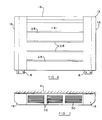
- a radiator assembly of the invention includes a single panel radiator 2 mounted on a wall 4 of a room by two laterally spaced vertical support brackets 6. Two laterally spaced pivot brackets 8 are secured to the wall 4, and each bracket has a vertical slot 10 therein.
- a radiator cover 12 is constructed of sheet metal and comprises a front face 14, an upper panel 16, two side panels 18 and a small lower panel 20.
- a series of vertically spaced grooves 28 extend horizontally along the front face 14, and a series of laterally spaced ventilation grills 30 are formed in the upper panel 16.
- Two inwardly extending tags 34 are formed in the upper part of the front face 14, adjacent to the side panels 18.
- Two restraint chains 36 are mounted to and extend between the tags 34 and corresponding anchor points 38 on the brackets 6. As shown in Figures 2 and 4, the length of these restraint chains 36 defines the position of the cover 12 when in its fully open position.
- the cover 12 is mounted on the pivot brackets 8 by means of two pivot pins 32 which are secured to and extend inwardly from respective side panels 18 to project through the slots 10. These pivot pins 32 are stepped to prevent undue lateral movement of the cover 12.
- a locking screw 40 having a circular stop flange 41 thereon, is in screw-threaded engagement with a housing member 42 secured to the inner surface of the lower part of one of the side panels 18. Access to the head 44 of the locking screw is provided by an aperture 46 in the side panel 18, the aperture 46 being smaller than the flange 41.
- the locking screw 40 When the cover 12 is in its closed position, the locking screw 40 is aligned with an aperture 48 in the associated pivot bracket 8. When the locking screw 40 is screwed into its advanced locking position the flange 41 abuts the housing member 42, and the screw 40 extends through the aperture 48 to prevent movement of the cover 12 relative to the radiator 2. When it is desired to move the cover 12 to its open position, the locking screw is unscrewed so as to withdraw the screw stem from the aperture 48, until the flange 41 abuts the side panel 18.
- the locking screw head 44 is designed so that it can be rotated by the radiator air venting key so as to withdraw or advance the screw.
- the arrangement of the threaded housing member 42 and the side panel 18 is such that a chamber 47 is formed in which the locking screw head 44 is restrained and allowed only sufficient axial movement for the screw to engage or disengage itself from the pivot bracket 8.
- This feature prevents inadvertent disengagement of the threads of the locking screw 40, and housing member 42.
- the cover 12 is shaped and dimensioned so that the rear edges of the upper panel 16 and the side panels 18 extend almost to the wall 4 when the cover 12 is in the closed position. This prevents people from reaching round the back of the cover 12 and touching the hot surfaces of the radiator, and also reduces the chances of debris falling onto the radiator.
- the radiator control valves and adjacent pipework are also enclosed by the cover 12 when the cover is in its closed position. This prevents people from being burnt by touching the pipework and control valves, and prevents interference with the radiator valve settings.
- the heater may be used with a thermostatically controlled radiator or heater valve.
- the thermostatic control head is mounted remotely from the heater.
- the illustrated radiator assembly has been designed so that the surface temperature of the cover 12 will not exceed 43°C when the radiator 2 is operating at a surface temperature of 75°C.
- the bottom cover 50 is fixed in position by screws which are operated by a vent key as is the locking screw 40.
Landscapes
- Engineering & Computer Science (AREA)
- General Engineering & Computer Science (AREA)
- Chemical & Material Sciences (AREA)
- Thermal Sciences (AREA)
- Combustion & Propulsion (AREA)
- Mechanical Engineering (AREA)
- Physics & Mathematics (AREA)
- Resistance Heating (AREA)
- Domestic Hot-Water Supply Systems And Details Of Heating Systems (AREA)
- Crystals, And After-Treatments Of Crystals (AREA)
- Thermotherapy And Cooling Therapy Devices (AREA)
- Control And Other Processes For Unpacking Of Materials (AREA)
- Surface Heating Bodies (AREA)
Claims (7)
- Raumheizungsanordnung mit einem Heizkörper zur feststehenden Anordnung an einer vertikalen Stützfläche (4) und einer einstückigen Abdeckung (12), die zur Umfassung des Heizkörpers (2) ausgebildet ist, wobei die Abdeckung (12) schwenkbar an einem oder mehrerer Stützrahmen (6) angeordnet ist, die ebenfalls an der Fläche (4) angeordnet sind und zur Schwenkbewegung zwischen einer geschlossenen Betriebsstellung, in der sie die vorderen, oberen und seitlichen Flächen des Heizkörpers (2) weitgehend umfaßt und einer offenen Stellung zur Gewährung eines Zugangs zu dem Heizkörper (2) ausgebildet ist, gekennzeichnet durch eine Arretiervorrichtung (40), welche innerhalb der Abdeckung enthalten ist zur Verriegelung der Abdeckung (12) in der geschlossenen Stellung und daß die Schwenkachse der Abdeckung (12) an dem einen oder den mehreren Stützrahmen (6) vertikal einstellbar ist, wodurch die Abdeckung (12) aus ihrer geschlossenen Stellung zu ihrer offenen Stellung bewegt ist durch Anheben der Abdeckung (12) und ihrer Verschwenkung von der Stützfläche (4) zur Gewährung von Zugang zu dem Heizkörper (2).
- Anordnung nach Anspruch 1, wobei der Heizkörper (2) die Form eines Heißwasserradiators (2) einnimmt.
- Anordnung nach Anspruch 2, wobei der Radiator (2) mit einem oder mehrerer Steuerventile zur Steuerung der Strömung von heißem Wasser durch den Radiator (2) versehen ist, wobei das Steuerventil oder die -ventile innerhalb der Abdeckung (12) angeordnet sind, wenn sich die Abdeckung (12) in der geschlossenen Stellung befindet.
- Anordnung nach einem der vorstehenden Ansprüche 2 oder 3, wobei der eine oder die mehreren Stützrahmen (6) nahe der Unterseite des Radiators (2) angeordnet sind, wodurch die Abdekkung (12) zu ihrer offenen Stellung bewegt ist durch Anheben der Abdeckung (12) und der Verschwenkung ihres oberen Abschnittes von der Stützfläche (4) weg.
- Anordnung nach einem der vorstehenden Ansprüche, wobei die Arretiervorrichtung (40) eine Schraubeneinrichtung (40) aufweist, die von der Abdeckung (12) getragen und durch eine Öffnung (46) darin zugänglich ist, wobei die Schraubeneinrichtung (40) mit einem Widerlager (48) an dem einen oder den mehreren Stützrahmen (6) zur Arretierung der Abdeckung (12) in der geschlossenen Position zusammenwirkt.
- Anordnung nach Anspruch 5, wobei der Heizkörper (2) in der Form eines Heißwasserradiators eine Entlüftungsschraube aufweist, die zur Betätigung mit einem Entlüftungsschlüssel ausgebildet ist und wobei die Schraubeneinrichtung (40) der Arretiervorrichtung (40) auch zur Betätigung durch den Entlüftungsschlüssel ausgebildet ist.
- Anordnung nach einem der vorstehenden Ansprüche, die an der Stützfläche (4) in beabstandetem Verhältnis zu einem Boden angeordnet ist, bei der eine Abdeckung (50) für die Unterseite vorgesehen ist, welche sich von der Abdeckung (12) bis zum Boden erstreckt.
Applications Claiming Priority (2)
| Application Number | Priority Date | Filing Date | Title |
|---|---|---|---|
| GB909022301A GB9022301D0 (en) | 1990-10-15 | 1990-10-15 | Heater assembly |
| GB9022301 | 1990-10-15 |
Publications (2)
| Publication Number | Publication Date |
|---|---|
| EP0483990A1 EP0483990A1 (de) | 1992-05-06 |
| EP0483990B1 true EP0483990B1 (de) | 1996-04-17 |
Family
ID=10683698
Family Applications (1)
| Application Number | Title | Priority Date | Filing Date |
|---|---|---|---|
| EP91309426A Expired - Lifetime EP0483990B1 (de) | 1990-10-15 | 1991-10-14 | Heizungsanordnung |
Country Status (6)
| Country | Link |
|---|---|
| EP (1) | EP0483990B1 (de) |
| AT (1) | ATE137007T1 (de) |
| DE (1) | DE69118811T2 (de) |
| DK (1) | DK0483990T3 (de) |
| FI (1) | FI96361C (de) |
| GB (2) | GB9022301D0 (de) |
Families Citing this family (12)
| Publication number | Priority date | Publication date | Assignee | Title |
|---|---|---|---|---|
| DK0542785T3 (da) * | 1990-07-20 | 1996-07-01 | Philip Ferdinando Villa | Justerbar plade- og monteringssamling |
| GB2263541B (en) * | 1992-01-25 | 1995-09-27 | Richard Steven Davies | Adjustable radiator screen |
| DE19707678A1 (de) * | 1997-02-26 | 1998-09-17 | Ulrich Zander | Schwenkbare Heizkörper - Teilverkleidung |
| DE29804583U1 (de) * | 1998-03-17 | 1999-04-22 | John Technik in Metall GmbH & Co. KG, 77855 Achern | Bewegliches Bekleidungsteil an Heizkörpern oder Heizkörperverkleidungen |
| FI112821B (fi) * | 1998-11-19 | 2004-01-15 | Rettig Laempoe Oy | Tuloilmalaite lämpöpatterien yhteydessä |
| SE518976C2 (sv) * | 1999-09-22 | 2002-12-10 | Mobitec Klimat Ab | Förfarande för att via hakorgan lösbart och dolt montera och låsa ett täcklock vid ett med ett flertal flänselement försett konvektorelement samt förfarande för montering av täcklock och konvektorelement vid ett väggparti |
| GB0104951D0 (en) * | 2001-02-28 | 2001-04-18 | Alumasc Interior Building Prod | Improved radiator guard |
| RU2262641C2 (ru) * | 2001-03-20 | 2005-10-20 | Аермек С.П.А. | Воздухораспределительный колпачок для конвектора |
| ITTV20050049U1 (it) * | 2005-10-10 | 2007-04-11 | Lazzarini S R L | Elemento di copertura a riscaldamento indotto del tipo rimovibile per scaldasalviette negli impianti idrotermici per ambienti. |
| PL2631584T3 (pl) * | 2012-02-22 | 2014-09-30 | Zehnder Verkaufs Und Verwaltungs Ag | Grzejnik |
| JP2020003079A (ja) * | 2018-06-25 | 2020-01-09 | 株式会社テスク | 柵状放熱体の周囲に輻射パネルを備えた冷暖房装置 |
| DK181836B1 (en) * | 2023-02-03 | 2025-02-17 | Frese As | A district heating system cabinet with a locking mechanism comprising a lock bolt |
Family Cites Families (8)
| Publication number | Priority date | Publication date | Assignee | Title |
|---|---|---|---|---|
| DE648949C (de) * | 1937-08-11 | Graepel Friedrich | Heizkoerperverkleidung | |
| GB329767A (en) * | 1929-04-05 | 1930-05-29 | Charles Adolf Schierwater | Improvements relating to radiators for heating buildings |
| GB330069A (en) * | 1929-04-18 | 1930-06-05 | Frederick Naunton Waller | Improvements in or relating to radiators for heating purposes |
| US2225722A (en) * | 1938-05-31 | 1940-12-24 | Modine Mfg Co | Convector or radiator cabinet |
| GB1330614A (en) * | 1971-04-01 | 1973-09-19 | Schmitz Kuehler Baierbrunn | Lamellar radiator for space heating |
| DE2355747A1 (de) * | 1973-11-08 | 1975-05-15 | Licentia Gmbh | Waermespeichergeraet |
| US4116507A (en) * | 1977-11-07 | 1978-09-26 | The Raymond Lee Organization, Inc. | Radiator concealing article of furniture |
| US4493794A (en) * | 1980-12-31 | 1985-01-15 | Fujisawa Pharmaceutical Co., Ltd. | Peptide, process for preparation thereof and use thereof |
-
1990
- 1990-10-15 GB GB909022301A patent/GB9022301D0/en active Pending
-
1991
- 1991-10-14 EP EP91309426A patent/EP0483990B1/de not_active Expired - Lifetime
- 1991-10-14 DK DK91309426.4T patent/DK0483990T3/da active
- 1991-10-14 DE DE69118811T patent/DE69118811T2/de not_active Expired - Fee Related
- 1991-10-14 FI FI914831A patent/FI96361C/fi not_active IP Right Cessation
- 1991-10-14 AT AT91309426T patent/ATE137007T1/de not_active IP Right Cessation
- 1991-10-14 GB GB9121771A patent/GB2248923B/en not_active Expired - Lifetime
Also Published As
| Publication number | Publication date |
|---|---|
| EP0483990A1 (de) | 1992-05-06 |
| FI96361B (fi) | 1996-02-29 |
| DE69118811T2 (de) | 1996-09-19 |
| FI914831A0 (fi) | 1991-10-14 |
| GB2248923A (en) | 1992-04-22 |
| DE69118811D1 (de) | 1996-05-23 |
| ATE137007T1 (de) | 1996-05-15 |
| FI914831A7 (fi) | 1992-04-16 |
| GB2248923B (en) | 1994-08-10 |
| DK0483990T3 (da) | 1996-08-12 |
| GB9121771D0 (en) | 1991-11-27 |
| GB9022301D0 (en) | 1990-11-28 |
| FI96361C (fi) | 1996-06-10 |
Similar Documents
| Publication | Publication Date | Title |
|---|---|---|
| EP0483990B1 (de) | Heizungsanordnung | |
| US2182106A (en) | Venting means for ranges or the like | |
| US6617954B2 (en) | Tamper resistant temperature controller for a gas-fired heating device | |
| EP2653240B1 (de) | Versenkbare Abzug-Herd Einheit | |
| US5647532A (en) | Air diffuser | |
| US2553278A (en) | Air conditioning apparatus | |
| US4509678A (en) | Thermally-powered control mechanism | |
| AU755770B2 (en) | Air diffuser | |
| US4750546A (en) | Automatic baseboard damper system | |
| US7441713B2 (en) | Tamper resistant temperature dial and associated method of use | |
| US4549160A (en) | Thermostat control apparatus | |
| US3167065A (en) | Combination cook stove and retractable oven | |
| US4319713A (en) | Stove blower control accessory | |
| US4171769A (en) | Temperature anticipator and night light apparatus | |
| US5341796A (en) | Turn in place mounting | |
| US2170728A (en) | Automatic draft regulator | |
| NO322343B1 (no) | Luftdistribusjonshette som skal tilpasses toppen av en varme- eller luftkondisjoneringsenhet | |
| US7145107B2 (en) | Tamper resistant temperature dial utilizing deflection pins | |
| EP4473885B1 (de) | Verbesserter thermostat und heizgerät mit diesem thermostat | |
| CN109737463B (zh) | 一种远红外电热炉 | |
| US8439027B2 (en) | Door control mechanism | |
| US1536689A (en) | Temperature-controlled heating device | |
| US4549159A (en) | Thermostat control apparatus | |
| US1521436A (en) | Automatic draft regulator | |
| JP3621281B2 (ja) | 液体燃焼器における燃料供給装置 |
Legal Events
| Date | Code | Title | Description |
|---|---|---|---|
| PUAI | Public reference made under article 153(3) epc to a published international application that has entered the european phase |
Free format text: ORIGINAL CODE: 0009012 |
|
| AK | Designated contracting states |
Kind code of ref document: A1 Designated state(s): AT BE CH DE DK ES FR GB GR IT LI LU NL SE |
|
| 17P | Request for examination filed |
Effective date: 19921027 |
|
| 17Q | First examination report despatched |
Effective date: 19930217 |
|
| GRAH | Despatch of communication of intention to grant a patent |
Free format text: ORIGINAL CODE: EPIDOS IGRA |
|
| GRAA | (expected) grant |
Free format text: ORIGINAL CODE: 0009210 |
|
| AK | Designated contracting states |
Kind code of ref document: B1 Designated state(s): AT BE CH DE DK ES FR GB GR IT LI LU NL SE |
|
| PG25 | Lapsed in a contracting state [announced via postgrant information from national office to epo] |
Ref country code: CH Effective date: 19960417 Ref country code: GR Free format text: LAPSE BECAUSE OF FAILURE TO SUBMIT A TRANSLATION OF THE DESCRIPTION OR TO PAY THE FEE WITHIN THE PRESCRIBED TIME-LIMIT Effective date: 19960417 Ref country code: ES Free format text: THE PATENT HAS BEEN ANNULLED BY A DECISION OF A NATIONAL AUTHORITY Effective date: 19960417 Ref country code: LI Effective date: 19960417 Ref country code: AT Effective date: 19960417 Ref country code: IT Free format text: LAPSE BECAUSE OF FAILURE TO SUBMIT A TRANSLATION OF THE DESCRIPTION OR TO PAY THE FEE WITHIN THE PRESCRIBED TIME-LIMIT;WARNING: LAPSES OF ITALIAN PATENTS WITH EFFECTIVE DATE BEFORE 2007 MAY HAVE OCCURRED AT ANY TIME BEFORE 2007. THE CORRECT EFFECTIVE DATE MAY BE DIFFERENT FROM THE ONE RECORDED. Effective date: 19960417 |
|
| REF | Corresponds to: |
Ref document number: 137007 Country of ref document: AT Date of ref document: 19960515 Kind code of ref document: T |
|
| ET | Fr: translation filed | ||
| REF | Corresponds to: |
Ref document number: 69118811 Country of ref document: DE Date of ref document: 19960523 |
|
| REG | Reference to a national code |
Ref country code: DK Ref legal event code: T3 |
|
| PGFP | Annual fee paid to national office [announced via postgrant information from national office to epo] |
Ref country code: SE Payment date: 19960923 Year of fee payment: 6 |
|
| PGFP | Annual fee paid to national office [announced via postgrant information from national office to epo] |
Ref country code: FR Payment date: 19960924 Year of fee payment: 6 |
|
| PGFP | Annual fee paid to national office [announced via postgrant information from national office to epo] |
Ref country code: BE Payment date: 19961009 Year of fee payment: 6 |
|
| PGFP | Annual fee paid to national office [announced via postgrant information from national office to epo] |
Ref country code: DK Payment date: 19961030 Year of fee payment: 6 |
|
| PG25 | Lapsed in a contracting state [announced via postgrant information from national office to epo] |
Ref country code: LU Free format text: LAPSE BECAUSE OF NON-PAYMENT OF DUE FEES Effective date: 19961031 |
|
| PGFP | Annual fee paid to national office [announced via postgrant information from national office to epo] |
Ref country code: NL Payment date: 19961031 Year of fee payment: 6 |
|
| REG | Reference to a national code |
Ref country code: CH Ref legal event code: PL |
|
| PGFP | Annual fee paid to national office [announced via postgrant information from national office to epo] |
Ref country code: DE Payment date: 19961129 Year of fee payment: 6 |
|
| PLBE | No opposition filed within time limit |
Free format text: ORIGINAL CODE: 0009261 |
|
| STAA | Information on the status of an ep patent application or granted ep patent |
Free format text: STATUS: NO OPPOSITION FILED WITHIN TIME LIMIT |
|
| 26N | No opposition filed | ||
| REG | Reference to a national code |
Ref country code: DK Ref legal event code: EBP |
|
| PG25 | Lapsed in a contracting state [announced via postgrant information from national office to epo] |
Ref country code: SE Free format text: LAPSE BECAUSE OF NON-PAYMENT OF DUE FEES Effective date: 19971015 |
|
| PG25 | Lapsed in a contracting state [announced via postgrant information from national office to epo] |
Ref country code: BE Free format text: LAPSE BECAUSE OF NON-PAYMENT OF DUE FEES Effective date: 19971031 Ref country code: FR Free format text: THE PATENT HAS BEEN ANNULLED BY A DECISION OF A NATIONAL AUTHORITY Effective date: 19971031 Ref country code: DK Free format text: LAPSE BECAUSE OF NON-PAYMENT OF DUE FEES Effective date: 19971031 |
|
| BERE | Be: lapsed |
Owner name: BLUE CIRCLE HEATING LTD (FORMERLY MYSON GROUP P.L Effective date: 19971031 |
|
| PG25 | Lapsed in a contracting state [announced via postgrant information from national office to epo] |
Ref country code: NL Free format text: LAPSE BECAUSE OF NON-PAYMENT OF DUE FEES Effective date: 19980501 |
|
| NLV4 | Nl: lapsed or anulled due to non-payment of the annual fee |
Effective date: 19980501 |
|
| PG25 | Lapsed in a contracting state [announced via postgrant information from national office to epo] |
Ref country code: DE Free format text: LAPSE BECAUSE OF NON-PAYMENT OF DUE FEES Effective date: 19980701 |
|
| EUG | Se: european patent has lapsed |
Ref document number: 91309426.4 |
|
| REG | Reference to a national code |
Ref country code: FR Ref legal event code: ST |
|
| REG | Reference to a national code |
Ref country code: GB Ref legal event code: 732E |
|
| REG | Reference to a national code |
Ref country code: GB Ref legal event code: 732E |
|
| REG | Reference to a national code |
Ref country code: GB Ref legal event code: IF02 |
|
| PGFP | Annual fee paid to national office [announced via postgrant information from national office to epo] |
Ref country code: GB Payment date: 20101012 Year of fee payment: 20 |
|
| REG | Reference to a national code |
Ref country code: GB Ref legal event code: PE20 Expiry date: 20111013 |
|
| PG25 | Lapsed in a contracting state [announced via postgrant information from national office to epo] |
Ref country code: GB Free format text: LAPSE BECAUSE OF EXPIRATION OF PROTECTION Effective date: 20111013 |