EP0484293B1 - Infraroter Anwesenheitsdetektor - Google Patents
Infraroter Anwesenheitsdetektor Download PDFInfo
- Publication number
- EP0484293B1 EP0484293B1 EP19910830462 EP91830462A EP0484293B1 EP 0484293 B1 EP0484293 B1 EP 0484293B1 EP 19910830462 EP19910830462 EP 19910830462 EP 91830462 A EP91830462 A EP 91830462A EP 0484293 B1 EP0484293 B1 EP 0484293B1
- Authority
- EP
- European Patent Office
- Prior art keywords
- lens
- sensor according
- fresnel
- sensor
- band
- Prior art date
- Legal status (The legal status is an assumption and is not a legal conclusion. Google has not performed a legal analysis and makes no representation as to the accuracy of the status listed.)
- Expired - Lifetime
Links
Images

Classifications
-
- G—PHYSICS
- G08—SIGNALLING
- G08B—SIGNALLING SYSTEMS, e.g. PERSONAL CALLING SYSTEMS; ORDER TELEGRAPHS; ALARM SYSTEMS
- G08B13/00—Burglar, theft or intruder alarms
- G08B13/18—Actuation by interference with heat, light, or radiation of shorter wavelength; Actuation by intruding sources of heat, light, or radiation of shorter wavelength
- G08B13/189—Actuation by interference with heat, light, or radiation of shorter wavelength; Actuation by intruding sources of heat, light, or radiation of shorter wavelength using passive radiation detection systems
- G08B13/19—Actuation by interference with heat, light, or radiation of shorter wavelength; Actuation by intruding sources of heat, light, or radiation of shorter wavelength using passive radiation detection systems using infrared-radiation detection systems
- G08B13/193—Actuation by interference with heat, light, or radiation of shorter wavelength; Actuation by intruding sources of heat, light, or radiation of shorter wavelength using passive radiation detection systems using infrared-radiation detection systems using focusing means
Definitions
- the present invention relates in general to infra-red presence sensors which can be used in anti-intrusion systems (anti-theft systems) for protecting spaces, particularly rooms in apartments and spaces in motor cars, or in other systems, for example, as presence detectors which can detect, for example, the entry of a person into a room and consequently switch on a device (e.g. a timed lighting device).
- a device e.g. a timed lighting device
- the present invention relates to a presence sensor having the features called for in the preamble of Claim 1, which is known, e.g. from GB-A-2 186 972, GB-A-2 215 454, US-A-4 841 284 or EP-A-0 337 964.
- a presence sensor having the features called for in the preamble of Claim 1, which is known, e.g. from GB-A-2 186 972, GB-A-2 215 454, US-A-4 841 284 or EP-A-0 337 964.
- a somewhat similar arrangement is disclosed in DE-A-37 10 561.
- the specific object of the present invention is to provide an infra-red presence sensor which is very compact without its compactness adversely affecting its performance.
- this object is achieved by virtue of a sensor having the further characteristics recited in claim 1.
- One of the main advantages of the sensor according to the invention is that it can be produced in the form of a so-called "module”, preferably a single module, which can be inserted in a connection box, a junction box, etc., or a similar element of a normal domestic electrical system. This is done in substantially the same way as with other modules such as switches, sockets, intensity regulators, etc.
- the main advantage offered by the invention is that it enables the conduits (or ducts) of the electrical system which is usually already present in the premises to be protected against intrusion or in which the presence of people is to be detected to be used for the installation of an anti-theft system. This minimises or even completely eliminates the need to provide further pipes or to use wireless systems for the connections between the sensors and the central control unit of the system.
- Another sector in which the sensor according to the invention can be used to particular advantage is the automotive sector.
- the present invention therefore provides a sensor which can solve the problems expressed above, particularly as regards the possibility of providing an anti-intrusion system for protecting spaces as original equipment supplied by the builder of the vehicle.
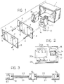
- Figure 1 shows schematically the component parts of a box (a connection, junction or terminal box) of a normal domestic or industrial electrical system.
- a so-called "module”, indicated 8 is intended to be mounted, in widely known manner, on the cover 2 in one of the holes 4.
- each hole has hook formations 9 which are intended to snap-engage corresponding hook formations on the body of the module 8.
- the module 8 is connected to the electrical system by means of respective wires (not shown specifically) which extend through the box 1 and enter the conduits or ducts (pipes) which extend through the walls of the premises in which the electrical system is fitted.
- the nature of the module 8 may vary widely; in fact it may be a switch, a regulator (a dimmer), an electrical or television socket, an indicator lamp, etc.
- the sensor according to the invention includes essentially a generally tank-shaped casing 11 which houses a monitoring circuit connected to an infra-red-sensitive element 12.
- the sensor is usually a so-called pyroelectric sensor which is sensitive, for example, to infra-red radiation in the range between 7 and 15 microns, with associated circuit elements 13, such as an amplifier and other members for pre-processing the signal generated by the sensitive element 12.
- a lens 14 is mounted on the front of the casing 11 which is intended to face the room in which the box is situated, the function of the lens being to focus the infra-red monitoring radiation coming from the room under surveillance towards the sensitive element 12.
- the lens 14 has Fresnel-lens characteristics.
- the lens 14 is a kind of "double lens” constituted by a spherical surface, that is, a cap-shaped surface, preferably with double curvature (the first lens) which has (preferably on its internal surface), for example, three bands 15, 16, 17 of Fresnel-lens segments (the second lens) one above another and including, for example, six, five and three Fresnel-lens segments.
- This configuration ensures the coverage of the area under surveillance which is divided into three regions, that is, an upper region (the band of segments 15), a central region (the band of segments 16) and a lower region (the band of segments 17).
- the area under surveillance is thus fully protected particularly in the so-called "man-height" region.
- the sensor 10 according to the invention can in fact be mounted in a box situated at the normal height for a switch and hence typically within a band 80 to 120 cm. from the ground.
- lens 14 has a very marked arcuate shape.
- it is spherical with a rectangular base, its configuration being comparable to a domed vault, and extends horizontally (in plan, when the sensor is in its normal position of use) through an angle of the order of 100-105° and vertically through an angle of the order of 45-60°.
- the lens 14 is preferably injection-moulded from plastics material, for example, high-density polyethylene and is quite thin, preferably less than 1 mm thick. This is to avoid excessive absorption of the monitoring radiation.
- the sensor 10 as a whole is a passive sensor.
- the lens 14 is intended (unlike a conventional anti-intrustion sensor which is usually mounted on the ceiling of the protected room) to be mounted in an easily accessible position and thus usually near another module such as a switch which is intended to be operated frequently even in the dark so that there is considerable exposure to pressures and knocks.
- the moulding of the lens 14 from plastics material also has the advantage that it enables the lens to be pigmented (for example, in black), for example, to provide it with colouring coordinated with that of the screen 5 for aesthetic purposes with a minimal addition of pigment (1-2 ⁇ ) and thus without adversely affecting its attenuation characteristics.
- an important characteristic of the lens 14 is that it is constituted, in practice, by a surface with double curvature, for example, a spherical surface, on which the Fresnel-lens segments are arranged in the adjacent bands 15, 16 and 17.
- the lens 14 may be compared to a kind of double lens, in the sense that it includes a spherical surface whose centre of curvature corresponds at least approximately to the position of the pyroelectric sensor 12 whilst the various Fresnel-lens segments (see, for example, the segments of the upper band 15 to which Figure 5 relates in greater detail) are formed so as to focus the infra-red radiation which reaches the sensor 10 precisely onto the spatial position occupied by the pyroelectric sensitive element 12; in other words, the sensitive element 12 is positioned at the focus of the various segments 15, 16 and 17.
- the distribution of the Fresnel-lens segments in the three bands 15, 16 and 17 one above another is intended primarily to achieve protection or surveillance in three different spatial regions.
- the segments of the upper band 15 are intended to cause the infra-red radiation coming from the upper portion of the area under surveillance to converge on the pyroelectric sensor 12 and the segments of the central band 16 are intended to focus the radiation coming from the central-lower region of the area under surveillance.
- the segments 17 of the lower band are intended to cause the radiation coming from the lower part of the area under surveillance and, in particular, from the portion of the area situated directly below the sensor 10 to converge on the sensor 12.
- the depth of the upper band 15 corresponds approximately to half the height of the lens 14 as a whole whilst the depths of the other two bands (the central band 16 and the lower band 17) are about half the lower portion, that is, one quarter of the overall height of the surface of the lens.
- the solution described which has three bands with six, five and three segments respectively, has also been found advantageous in that a certain angular staggering of the serpents in the various bands can be achieved.
- each serpent uses a smaller number of segments in the lower bands and, in particular, in the lowest band 17 to have a larger surface which improves the picking-up of the infra-red radiation in the lower regions which are angularly more remote from the central axis of the pyroelectric sensor.
- the lens 14 has a base or skirt portion 19 which is generally prismatic (with a rectangular cross-section in the embodiment shown) which enables the lens 14 to be mounted in a position such that, with the face 19a of the casing 11 which holds the circuits associated with the pyroelectric sensor 12, it defines a chamber which is substantially closed to the exterior, for housing the element 12.
- This arrangement has the advantage of insulating the pyroelectricelement 12 from phenomena such as, for example, draughts which could disturb its operation, for example, causing the pyroelectric element to generate alarm signals in conditions in which the emission of such a signal is actually unjustified (so-called false alarms).
- the casing 11 including the lens 14 disposed on its front face, can be formed so as to have dimensions which fully correspond to those of a normal module.
- the senor 10 can assume the characteristics of a so-called single module which is intended to occupy a single mounting position in the box 1.
- the lens 14 can be formed so that the radius of its spherical surface is of the order of 14 mm and the dimensions of its base (the sides of the prismatic skirt portion 19) are 16 x 20 mm so that the lens 14 (and the sensor 10 as a whole) can be fitted in a casing 11 for electrical modules conforming to the European standard (maximum width 25 mm).
- Figure 2 and the left-hand portion of Figure 3 also show how - precisely because of the small size of the sensor itself - the sensor 10 can be combined, in at least one of the boxes, with a more complex processing member, for example, the central control unit 20 which controls the operation of the system formed by the various sensors 10 and may be capable of being activated and deactivated selectively by remote control (20b) so that certain sensors 10 can be made inoperative (partial shutting-down), for example, in order to retain protection only in certain rooms whilst others continue to be used (for example, during the night).
- the central control unit 20 which controls the operation of the system formed by the various sensors 10 and may be capable of being activated and deactivated selectively by remote control (20b) so that certain sensors 10 can be made inoperative (partial shutting-down), for example, in order to retain protection only in certain rooms whilst others continue to be used (for example, during the night).
- a microwave sensor is associated with a sensor 10 within the same connection box in order to provide the system with better protection against attempted masking or obstruction.
- the arrangement of the Fresnel-lens serpents it is possible to adopt either the arrangement with several bands one above another, of which the bands of Fresnel-lens segments 15, 16 and 17 of Figure 4 are an example, or a different arrangement, for example, including identical bands, one above the other, or three bands of different lengths, one above another in a cross-shaped arrangement.
- the front seats S1 and the rear seats S2 of the car are visible, however, and are shown schematically.
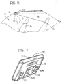
- a so-called ceiling light 100 is fitted in the passenger compartment in a central position on the front edge of the roof above the upper edge of the windscreen P.
- This element which is shown in greater detail in Figure 7 includes, in known manner, devices such as, for example, a clock 102 and one or more switches 103, 104 disposed in positions in which they are easily visible and/or accessible to the people in the passenger compartment.
- devices such as, for example, a clock 102 and one or more switches 103, 104 disposed in positions in which they are easily visible and/or accessible to the people in the passenger compartment.
- a sensor 10 substantially similar to that described above is mounted in the ceiling light 100 and is intended to act as an anti-intrusion (anti-theft) sensor of the type for protecting a space.
- the senor 10 is constituted by a box-shaped body 11 which can be fitted or engaged in the ceiling light 100 so that it can be fitted in the vehicle as original equipment.
- This solution enables the sensor 10 to be connected to the central control unit of the anti-theft system, which usually also includes other sensors (sensitive to events such as an attempt to open the doors, an attempt to start the engine, etc.) and can be activated/deactivated remotely by signals transmitted to the central control unit by a remote control.
- the positioning of the sensor 10 in the ceiling light 100 enables it to be connected to the central control unit by making direct use of the conduits which are usually already provided in the passenger compartment for the wires of the vehicle's electrical system. This is not usually true of current anti-theft systems for which the fitter, who operates on the finished vehicle, usually has to provide wires and conduits specifically for connecting the sensors to the central control unit.
- the lens is also characterised by two important factors, that is:
- the field covered by the sensor 10 in the passenger compartment W is shown schematically in Figure 6 and has a central or middle region of coverage A (the band of segments 16) which includes essentially the upper portions of the front seats S1 and a good portion of the rear seats S2, an upper region of coverage B (the band 15) which includes the upper portions of the rear seats S2 and the rear window, and a lower region of coverage C (the band 17) which includes the sitting surfaces of the front seats S1 and members such as the gear lever, etc.
- A the band of segments 16
- B the band 15
- C the band 17
- the very arcuate shape of the lens 14 is intended to give it a generally dome-shaped configuration and consequently resistance to mechanical compression stresses exerted on the lens 14.
- the lens is usually made of fairly thin plastics material in order to prevent eccessive attenuation of the radiation used for the monitoring; the sensor 10 is in fact a passive sensor.
- the senor 10 according to the invention is characterised by an extremely low level of energy consumption so that the anti-intrusion system as a whole (including the central control unit to which the sensor 10 is connected) has consumption characteristics considerably lower than those of the ultrasound or microwave anti-intrusion systems currently used with which, however, the sensor according to the invention can easily be combined.
Landscapes
- Physics & Mathematics (AREA)
- General Physics & Mathematics (AREA)
- Photometry And Measurement Of Optical Pulse Characteristics (AREA)
- Burglar Alarm Systems (AREA)
Claims (22)
- Anwesenheitssensor (10), umfassend:- ein infrarotempfindliches Element (12), und- eine Linse (14) zum Fokussieren der Überwachungsstrahlung auf das empfindliche Element (12), wobei die Linse (14) eine Vielzahl an ihrer Oberfläche ausgebildeter Fresnel-Linsensegmente aufweist, welche in drei benachbarten Bändern (15 bis 17) angeordnet sind,dadurch gekennzeichnet,
daß die Linse (14) eine haubenförmige Oberfläche mit Doppelkrümmung aufweist, wobei die benachbarten Bänder (15 bis 17) von Fresnel-Linsensegmenten definieren:- ein oberes Band (15), das bewirkt, daß die aus einem oberen Abschnitt eines unter Überwachung stehenden Bereichs kommende Strahlung auf dem empfindlichen Element (12) konvergiert;- ein zentrales Band (16) zum Fokussieren der aus dem zentral unteren Gebiet eines unter Überwachung stehenden Bereichs kommenden Strahlung auf das empfindliche Element (12); und- ein unteres Band (17), das bewirkt, daß die aus dem unteren Abschnitt eines unter Überwachung stehenden Bereichs kommende Strahlung auf dem empfindlichen Element (12) konvergiert. - Sensor nach Anspruch 1,
dadurch gekennzeichnet,
daß er ein Gehäuse (11) mit derartigen Abmessungen umfaßt,
daß der Sensor (10) im Ganzen als ein Modul, vorzugsweise ein einzelnes Modul, ausgeführt ist, welches in einen Gehäusekas- ten (1 bis 7) oder dergleichen eines elektrischen Systems eingesetzt werden kann. - Sensor nach Anspruch 1 oder 2,
dadurch gekennzeichnet,
daß die Fresnel-Linsensegmente (15 bis 17) auf der Innenseite der haubenförmigen Oberfläche angeordnet sind. - Sensor nach Anspruch 1,
dadurch gekennzeichnet,
daß die benachbarten Bänder (15 bis 17) winkelig versetzte Fresnel-Linsensegmente umfassen. - Sensor nach Anspruch 1 oder 4,
dadurch gekennzeichnet,
daß die Anzahl von Fresnel-Linsensegmenten in den Bändern (15 bis 17) allgemein von Band zu Band variiert. - Sensor nach Anspruch 1,
dadurch gekennzeichnet,
daß die Linse (14) ein zentrales Band (16) von Fresnel-Linsensegmenten und zwei weitere Bänder (15 und 17) von Fresnel-Linsensegmenten oberhalb (15) bzw. unterhalb (17) des zentralen Bandes (16) umfaßt. - Sensor nach Anspruch 1 oder 6,
dadurch gekennzeichnet,
daß die benachbarten Bänder (15 bis 17) gleiche Abmessungen haben. - Sensor nach Anspruch 6,
dadurch gekennzeichnet,
daß das obere Band (15) von Fesnel-Linsensegmenten etwa die Hälfte der haubenförmigen Oberfläche der Linse (14) einnimmt. - Sensor nach Anspruch 6 oder 8,
dadurch gekennzeichnet,
daß das zentrale Band (16) und das untere Band (17) jeweils etwa ein Viertel der haubenförmigen Oberfläche der Linse (14) einnehmen. - Sensor nach einem der vorhergehenden Ansprüche,
dadurch gekennzeichnet,
daß die haubenförmige Oberfläche der Linse (14) im wesentlichen sphärisch ist. - Sensor nach Anspruch 1 oder 10,
dadurch gekennzeichnet,
daß sich die Linse (14) horizontal über einen Winkel der Größenordnung von 90 - 105° erstreckt. - Sensor nach einem der Ansprüche 1, 10 oder 11,
dadurch gekennzeichnet,
daß sich die Linse (14) vertikal über einen Winkel der Größenordnung von 45 - 60° erstreckt. - Sensor nach einem der vorhergehenden Ansprüche,
dadurch gekennzeichnet,
daß die Form der haubenförmigen Oberfläche allgemein mit der eines gewölbten Gewölbes vergleichbar ist. - Sensor nach einem der vorhergehenden Ansprüche,
dadurch gekennzeichnet,
daß die Linse (14) von einem Körper mit einem Randabschnitt (19) begrenzt ist, welcher das infrarotempfindliche Element (12) derart umschließt, daß es von der Außenumgebung isoliert ist. - Sensor nach einem der vorhergehenden Ansprüche,
dadurch gekennzeichnet,
daß die Linse (14) aus einem Kunststoffmaterial geformt ist, vorzugsweise durch Spritzgießen. - Sensor nach Anspruch 1 oder 15,
dadurch gekennzeichnet,
daß die Linse (14) aus einem Kunststoffmaterial, wie z.B. Polyethylen mit hoher Dichte, hergestellt ist. - Sensor nach Anspruch 1,
dadurch gekennzeichnet,
daß die haubenförmige Oberfläche der Linse (14) weniger als 1 mm dick ist. - Sensor nach Anspruch 1 oder einem der Ansprüche 15 bis 17,
dadurch gekennzeichnet,
daß die Linse (14) pigmentiert ist. - Sensor nach einem der vorhergehenden Ansprüche, als ein Element eines Anwesenheitsdetektionssystems in einem Raum, wobei das System Verbindungsdrähte (21) umfaßt, die sich durch die Leitungskanäle (22) des elektrischen Systems des Raums erstrecken, in welchem das System angebracht ist.
- Sensor nach Anspruch 19, der in seinem Gehäusekasten (1 bis 7) oder dergleichen mit einer Steuereinheit (20) des Anwesenheitsdetektionssystems, möglicherweise mit einer Fernsteuerung (20b), kombiniert ist.
- Sensor nach Anspruch 1,
dadurch gekennzeichnet,
daß er in einen Leuchtkörper oder ein ähnliches Zubehörteil (100) eingebaut ist, welches in einem Abschnitt des Fahrgastraums (A) eines Kraftfahrzeugs angebracht ist. - Sensor nach einem der vorhergehenden Ansprüche,
dadurch gekennzeichnet,
daß er mit einem Ultraschall- oder Mikrowellensensor kombiniert ist.
Priority Applications (1)
| Application Number | Priority Date | Filing Date | Title |
|---|---|---|---|
| AT91830462T ATE100232T1 (de) | 1990-10-29 | 1991-10-29 | Infraroter anwesenheitsdetektor. |
Applications Claiming Priority (4)
| Application Number | Priority Date | Filing Date | Title |
|---|---|---|---|
| IT67835A IT1240567B (it) | 1990-10-29 | 1990-10-29 | Sensore anti-intrusione per veicoli |
| IT5334290U | 1990-10-29 | ||
| IT6783590 | 1990-10-29 | ||
| IT5334290U IT225167Z2 (it) | 1990-10-29 | 1990-10-29 | Sensore anti-intrusione all'infrarosso, particolarmente per il montaggio quale frutto in scatole di impianti elettrici e dispositivi similari. |
Publications (3)
| Publication Number | Publication Date |
|---|---|
| EP0484293A2 EP0484293A2 (de) | 1992-05-06 |
| EP0484293A3 EP0484293A3 (en) | 1992-06-17 |
| EP0484293B1 true EP0484293B1 (de) | 1994-01-12 |
Family
ID=26329566
Family Applications (1)
| Application Number | Title | Priority Date | Filing Date |
|---|---|---|---|
| EP19910830462 Expired - Lifetime EP0484293B1 (de) | 1990-10-29 | 1991-10-29 | Infraroter Anwesenheitsdetektor |
Country Status (2)
| Country | Link |
|---|---|
| EP (1) | EP0484293B1 (de) |
| DE (1) | DE69101002T2 (de) |
Cited By (1)
| Publication number | Priority date | Publication date | Assignee | Title |
|---|---|---|---|---|
| DE10231016A1 (de) * | 2002-07-09 | 2004-01-29 | Daimlerchrysler Ag | Verfahren und Vorrichtung zur Erfassung der Körperposition |
Families Citing this family (4)
| Publication number | Priority date | Publication date | Assignee | Title |
|---|---|---|---|---|
| GB9215757D0 (en) * | 1992-07-24 | 1992-09-09 | Bridisco Ltd | A pir sensor device |
| ITMI20011024A1 (it) * | 2001-05-17 | 2002-11-17 | Vimar Spa | Lente di fresnel segmentata |
| FR2852402B1 (fr) | 2003-03-13 | 2005-04-29 | Dispositif de detection a infrarouge | |
| US9830789B2 (en) * | 2015-12-29 | 2017-11-28 | Honeywell International Inc. | Ceiling mount intrusion detector with arbitrary direction detection capability |
Family Cites Families (6)
| Publication number | Priority date | Publication date | Assignee | Title |
|---|---|---|---|---|
| AU580898B2 (en) * | 1986-02-25 | 1989-02-02 | Matsushita Electric Works Ltd. | Infrared detector |
| DE3710561A1 (de) * | 1987-03-30 | 1988-10-13 | Kopp Gmbh & Co Kg Heinrich | Infrarot-bewegungsmelder |
| US4823051A (en) * | 1987-05-21 | 1989-04-18 | Pittway Corporation | Infrared actuated control switch assembly |
| US4841284A (en) * | 1987-10-19 | 1989-06-20 | C & K Systems, Inc. | Infrared intrusion detection system incorporating a fresnel lens and a mirror |
| GB2215454B (en) * | 1988-03-09 | 1991-09-11 | Racal Guardall | Security sensors |
| IT1219751B (it) * | 1988-04-13 | 1990-05-24 | Elkron Spa | Dispositivo rivelatore combinato a microonde e raggi infrarossi particolarmente per sistemi anti intrusione |
-
1991
- 1991-10-29 EP EP19910830462 patent/EP0484293B1/de not_active Expired - Lifetime
- 1991-10-29 DE DE1991601002 patent/DE69101002T2/de not_active Expired - Fee Related
Cited By (1)
| Publication number | Priority date | Publication date | Assignee | Title |
|---|---|---|---|---|
| DE10231016A1 (de) * | 2002-07-09 | 2004-01-29 | Daimlerchrysler Ag | Verfahren und Vorrichtung zur Erfassung der Körperposition |
Also Published As
| Publication number | Publication date |
|---|---|
| EP0484293A3 (en) | 1992-06-17 |
| DE69101002D1 (de) | 1994-02-24 |
| EP0484293A2 (de) | 1992-05-06 |
| DE69101002T2 (de) | 1994-05-05 |
Similar Documents
| Publication | Publication Date | Title |
|---|---|---|
| CA2548701C (en) | Occupancy sensor assembly | |
| US5689304A (en) | Indoor/outdoor surveillance housing | |
| MXPA97007776A (en) | Multifunction occupation sensor | |
| US5940122A (en) | Housing assembly for housing a surveillance television camera | |
| CA2972487C (en) | Security device for integration into a security system | |
| EP0817148B1 (de) | Sicherheitssystem mit Lichtleitmedien | |
| EP0484293A2 (de) | Infraroter Anwesenheitsdetektor | |
| US10553088B2 (en) | Security device for integration into a security system | |
| US5930355A (en) | Protection device for telephone line and interface | |
| CA2183141A1 (en) | Remotely actuated light | |
| RU2242382C2 (ru) | Компьютерная система охраны транспортных средств | |
| JP2561375Y2 (ja) | 建築物用扉の鍵孔照光装置 | |
| Honey | Electronic Protection and Security Systems: A Handbook for Installers and Users | |
| WO1999019666A1 (en) | Lamp fitting and monitoring device | |
| EP4187516B1 (de) | Teilesatz mit einer sensoreinheit und sensoreinheit die davon erzeugt worden ist | |
| JP3061836U (ja) | 警報防犯装置 | |
| JP2729161B2 (ja) | 警報装置 | |
| CN100401327C (zh) | 一种安防探测或感应装置 | |
| FR2845810A1 (fr) | Systeme de protection contre les intrusions | |
| JP2916697B2 (ja) | 防犯用人体検知器 | |
| JPH0737399Y2 (ja) | ドアホン子器 | |
| JP2756472B2 (ja) | 熱線式検出器 | |
| GB2235316A (en) | Infra red intruder detector | |
| CN2270100Y (zh) | 改进的保险柜 | |
| Antunes | Intruder alarm systems: the state of the art |
Legal Events
| Date | Code | Title | Description |
|---|---|---|---|
| PUAI | Public reference made under article 153(3) epc to a published international application that has entered the european phase |
Free format text: ORIGINAL CODE: 0009012 |
|
| PUAL | Search report despatched |
Free format text: ORIGINAL CODE: 0009013 |
|
| AK | Designated contracting states |
Kind code of ref document: A2 Designated state(s): AT BE CH DE DK ES FR GB GR IT LI LU NL SE |
|
| AK | Designated contracting states |
Kind code of ref document: A3 Designated state(s): AT BE CH DE DK ES FR GB GR IT LI LU NL SE |
|
| 17P | Request for examination filed |
Effective date: 19920929 |
|
| 17Q | First examination report despatched |
Effective date: 19930219 |
|
| GRAA | (expected) grant |
Free format text: ORIGINAL CODE: 0009210 |
|
| AK | Designated contracting states |
Kind code of ref document: B1 Designated state(s): AT BE CH DE DK ES FR GB GR IT LI LU NL SE |
|
| PG25 | Lapsed in a contracting state [announced via postgrant information from national office to epo] |
Ref country code: SE Effective date: 19940112 Ref country code: CH Effective date: 19940112 Ref country code: AT Effective date: 19940112 Ref country code: ES Free format text: THE PATENT HAS BEEN ANNULLED BY A DECISION OF A NATIONAL AUTHORITY Effective date: 19940112 Ref country code: GR Free format text: LAPSE BECAUSE OF FAILURE TO SUBMIT A TRANSLATION OF THE DESCRIPTION OR TO PAY THE FEE WITHIN THE PRESCRIBED TIME-LIMIT Effective date: 19940112 Ref country code: LI Effective date: 19940112 Ref country code: NL Effective date: 19940112 Ref country code: DK Effective date: 19940112 |
|
| REF | Corresponds to: |
Ref document number: 100232 Country of ref document: AT Date of ref document: 19940115 Kind code of ref document: T |
|
| ITF | It: translation for a ep patent filed | ||
| REF | Corresponds to: |
Ref document number: 69101002 Country of ref document: DE Date of ref document: 19940224 |
|
| REG | Reference to a national code |
Ref country code: CH Ref legal event code: PL |
|
| ET | Fr: translation filed | ||
| NLV1 | Nl: lapsed or annulled due to failure to fulfill the requirements of art. 29p and 29m of the patents act | ||
| PG25 | Lapsed in a contracting state [announced via postgrant information from national office to epo] |
Ref country code: LU Free format text: LAPSE BECAUSE OF NON-PAYMENT OF DUE FEES Effective date: 19941031 |
|
| PLBE | No opposition filed within time limit |
Free format text: ORIGINAL CODE: 0009261 |
|
| STAA | Information on the status of an ep patent application or granted ep patent |
Free format text: STATUS: NO OPPOSITION FILED WITHIN TIME LIMIT |
|
| 26N | No opposition filed | ||
| PGFP | Annual fee paid to national office [announced via postgrant information from national office to epo] |
Ref country code: BE Payment date: 20010925 Year of fee payment: 11 |
|
| REG | Reference to a national code |
Ref country code: GB Ref legal event code: IF02 |
|
| PG25 | Lapsed in a contracting state [announced via postgrant information from national office to epo] |
Ref country code: BE Free format text: LAPSE BECAUSE OF NON-PAYMENT OF DUE FEES Effective date: 20021031 |
|
| BERE | Be: lapsed |
Owner name: *TEKNOX S.R.L. Effective date: 20021031 |
|
| PGFP | Annual fee paid to national office [announced via postgrant information from national office to epo] |
Ref country code: GB Payment date: 20061025 Year of fee payment: 16 |
|
| PGFP | Annual fee paid to national office [announced via postgrant information from national office to epo] |
Ref country code: DE Payment date: 20061026 Year of fee payment: 16 |
|
| GBPC | Gb: european patent ceased through non-payment of renewal fee |
Effective date: 20071029 |
|
| PG25 | Lapsed in a contracting state [announced via postgrant information from national office to epo] |
Ref country code: DE Free format text: LAPSE BECAUSE OF NON-PAYMENT OF DUE FEES Effective date: 20080501 |
|
| REG | Reference to a national code |
Ref country code: FR Ref legal event code: ST Effective date: 20080630 |
|
| PGFP | Annual fee paid to national office [announced via postgrant information from national office to epo] |
Ref country code: FR Payment date: 20061010 Year of fee payment: 16 |
|
| PG25 | Lapsed in a contracting state [announced via postgrant information from national office to epo] |
Ref country code: GB Free format text: LAPSE BECAUSE OF NON-PAYMENT OF DUE FEES Effective date: 20071029 |
|
| PG25 | Lapsed in a contracting state [announced via postgrant information from national office to epo] |
Ref country code: FR Free format text: LAPSE BECAUSE OF NON-PAYMENT OF DUE FEES Effective date: 20071031 |
|
| PGFP | Annual fee paid to national office [announced via postgrant information from national office to epo] |
Ref country code: IT Payment date: 20101005 Year of fee payment: 20 |