EP0484473B1 - Trepan a buses - Google Patents
Trepan a buses Download PDFInfo
- Publication number
- EP0484473B1 EP0484473B1 EP91906677A EP91906677A EP0484473B1 EP 0484473 B1 EP0484473 B1 EP 0484473B1 EP 91906677 A EP91906677 A EP 91906677A EP 91906677 A EP91906677 A EP 91906677A EP 0484473 B1 EP0484473 B1 EP 0484473B1
- Authority
- EP
- European Patent Office
- Prior art keywords
- drill head
- nozzles
- nozzle
- channel
- center axis
- Prior art date
- Legal status (The legal status is an assumption and is not a legal conclusion. Google has not performed a legal analysis and makes no representation as to the accuracy of the status listed.)
- Expired - Lifetime
Links
- 238000005553 drilling Methods 0.000 claims abstract description 16
- 239000012530 fluid Substances 0.000 description 4
- 239000011435 rock Substances 0.000 description 3
- 239000007921 spray Substances 0.000 description 2
- 230000006641 stabilisation Effects 0.000 description 2
- 239000000126 substance Substances 0.000 description 2
- 239000002253 acid Substances 0.000 description 1
- 150000007513 acids Chemical class 0.000 description 1
- 229910000278 bentonite Inorganic materials 0.000 description 1
- 239000000440 bentonite Substances 0.000 description 1
- SVPXDRXYRYOSEX-UHFFFAOYSA-N bentoquatam Chemical compound O.O=[Si]=O.O=[Al]O[Al]=O SVPXDRXYRYOSEX-UHFFFAOYSA-N 0.000 description 1
- 230000006735 deficit Effects 0.000 description 1
- 230000001419 dependent effect Effects 0.000 description 1
- 230000000694 effects Effects 0.000 description 1
- 239000003673 groundwater Substances 0.000 description 1
- 239000000463 material Substances 0.000 description 1
- 239000008267 milk Substances 0.000 description 1
- 238000007493 shaping process Methods 0.000 description 1
- 239000007779 soft material Substances 0.000 description 1
- 238000005507 spraying Methods 0.000 description 1
Images

Classifications
-
- E—FIXED CONSTRUCTIONS
- E21—EARTH OR ROCK DRILLING; MINING
- E21B—EARTH OR ROCK DRILLING; OBTAINING OIL, GAS, WATER, SOLUBLE OR MELTABLE MATERIALS OR A SLURRY OF MINERALS FROM WELLS
- E21B7/00—Special methods or apparatus for drilling
- E21B7/04—Directional drilling
- E21B7/06—Deflecting the direction of boreholes
- E21B7/065—Deflecting the direction of boreholes using oriented fluid jets
-
- E—FIXED CONSTRUCTIONS
- E21—EARTH OR ROCK DRILLING; MINING
- E21B—EARTH OR ROCK DRILLING; OBTAINING OIL, GAS, WATER, SOLUBLE OR MELTABLE MATERIALS OR A SLURRY OF MINERALS FROM WELLS
- E21B10/00—Drill bits
- E21B10/60—Drill bits characterised by conduits or nozzles for drilling fluids
-
- E—FIXED CONSTRUCTIONS
- E21—EARTH OR ROCK DRILLING; MINING
- E21B—EARTH OR ROCK DRILLING; OBTAINING OIL, GAS, WATER, SOLUBLE OR MELTABLE MATERIALS OR A SLURRY OF MINERALS FROM WELLS
- E21B7/00—Special methods or apparatus for drilling
- E21B7/18—Drilling by liquid or gas jets, with or without entrained pellets
Definitions
- the invention relates to a drill head as part of a drill lance for an apparatus for drilling an underground tunnel, comprising a drill head which has a channel extending along the center axis of the drill lance and is rotatable about the center axis, at least one forwardly directed nozzle on the drill head which communicates with the channel and the outlet opening of which is aligned outside the center axis.
- Such drill lances are used with apparatus which serve to drill underground channels. Fluid under pressure exits from the forwardly directed nozzle, for example a water-bentonite-milk.
- An even drilling in the forward direction through substantially homogeneous earth is achieved by rotating the drill head together with the drilling lance with an even rotational velocity about the center axis.
- the rotational movement is stopped as soon as the nozzle of the drill head is located approximately in the position at which the change in direction is to begin.
- Earth is preferably only removed in one direction through the fluid jet emitting out of the nozzle.
- the entire boring lance is turned until the new direction has been set.
- This hydromechanical steering is often supported by a control surface which is formed by a chamferring of the drill head located opposite the nozzle. The rotational movement of the drill head is then started again and a linear drilling ensues in the new direction.
- Such a drill head for a drill lance is known from EP-0 195 559 Al.
- a different number of nozzles is selected accordingly.
- sufficiently exact drillings can be carried out so long as the underground consists of relatively soft earth.
- difficulties arise in the stabilisation of the drill lance as the side of the drilling lance lying opposite the nozzle arrangement hits against the hard rock which results in steering problems with the lance during the relatively slow advance.
- US-4 850 440 discloses a steerable drill head having a plurality of direction-adjustable spray nozzles.
- the steering of this known drill head is achieved by spraying through spray nozzles being directed away from the end of the drill head such that the head is repelled from the wall of the already-formed bore hole.
- the inventive drill head is characterized in that at least one rearwardly directed nozzle is provided on the drill head, the nozzle channel of which communicates with the channel extending along the center axis of the drill head.
- a nozzle directed in this way provides the drill lance with space so that it can manoeuver better during changes in direction.
- the steering capability of the drill lance is thus significantly improved.
- the drill head has a plurality of rearwardly directed nozzles which are provided at the same angular distance from one another with respect to the center axis, although embodiments with different angular distances are also possible. It has been determined that for certain ground conditions three nozzles aligned at a distance of 120° are sufficient in order to give the drill lance sufficient clearance during changes in direction of any kind. Other ground conditions can require a different arrangement of four or more rearwardly directed nozzles.
- the drill head can also have a plurality of forwardly directed nozzles which are arranged symmetrically with regard to their angular distance to one of these nozzles.
- the nozzle distance with respect to the central one of these nozzles respectively amounts to 45°.
- the nozzles can be forwardly directed at an angle of approximately 10° to 15° with respect to the center axis of the drill lance, the outlet opening of the nozzles being aligned outside the center axis but arranged parallel to this.
- the axis of the nozzle channel of at least one rearwardly directed nozzle and the axis of the nozzle channel of one forwardly directed nozzle lie in a plane common with the center axis.
- the required quantity of bentonite for the drilling is smallest, which can be useful in some types of application.
- a drill head 1 is shown. Fluid under high pressure enters through the truncated cone-shaped opening 13 of a central channel 10 in the drill head 1.
- the center channel 10 extends almost up to the front surface 14 of the drill head 1.
- the drill head is coupled with the further apparatus necessary for drilling, a key 3 being provided to secure against rotation.
- the drill head 1 ends with a thread 12 by means of which it is possible to screw the drill head 1 to the apparatus additionally required for drilling.
- Nozzle channels 21, 41 of two nozzle systems enter into the end region of the center channel 10 in the vicinity of the front surface 14 of the drill head 1.
- the first nozzle system consists of forwardly directed nozzles 2 which exit into the front surface 14 of the drill head 1 outside the axis of the center channel 10.
- the second nozzle system comprises rearwardly directed nozzles 4, the respective outlet openings of which are directed against the actual advancing direction of the drill head 1 at a certain angle to the axis of the center channel 10, which angle can, for example, be 15°.
- a recess 43 is provided in which the nozzle 4 is sunk.
- known nozzles 2, 4 can be used which are provided with a hardened nozzle orifice blade 22, 42.
- the nozzle channels 21 of the first nozzle system are aligned at an angle of 11°, for example, with respect to the axis of the center channel 10.
- the first nozzle system is located in this depiction in the region above the axis of the center channel 10.
- the lower region is increasingly chamferred towards the front surface 14 and forms a control surface 11. During a change in direction of the drilling, this control surface 11 lies against the earth and contributes to the stabilisation of the drill lance.
- Fig. 2 shows a front view of the drill head.
- Three nozzles 2, 2', 2" exit into the front surface 14 of the drill head 1.
- Two of the nozzles 2', 2" are displaced at an angle of 45° with respect to the centrally arranged nozzle 2.
- the arrangement of the control surface 11 implies that the drill head 1 has an elliptical section in cross section as a portion thereof.
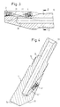
- Fig. 3 shows the drill head of the lance as in Fig. 1 in section along the line A-A in Fig. 2.
- the sectional view clearly shows that the axes of the nozzle channels 21, 41 and the axis of the center channel 10 lie in one plane.
- Fig. 4 shows the drill lance in section along the line B-B in Fig. 2.
- the nozzle channel 41' of a second nozzle 4' of the second nozzle system which is directed rearwardly in the advancing direction, enters at the end of the center channel 10.
- the elliptically-shaped cross section of the drill head 1 implies that the control surface 11 appears as a steeply chamferred surface in this sectional direction. Such a shaping of the control surface 11 effects a preferred direction during the drilling.
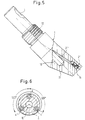
- Fig. 5 shows the drill lance depicted partially in elevation, the section lying along the line C-C in Fig. 2.
- the drill lance is secured against rotation by a key 3 located in a keyway.
- the nozzle channel 21' enters in the lower region of the center channel 10, but not at its end.
- Fig. 6 shows the drill head in section along the line D-D in Fig. 3, wherein three nozzles 4, 4', 4" are arranged at an angular distance of 120° from one another at the periphery of the drill head 1. This arrangement of the three nozzles 4, 4', 4" is sufficient to ensure substantial evading movement of the drill lance while a change in direction is effected.
Landscapes
- Engineering & Computer Science (AREA)
- Geology (AREA)
- Life Sciences & Earth Sciences (AREA)
- Mining & Mineral Resources (AREA)
- Environmental & Geological Engineering (AREA)
- Fluid Mechanics (AREA)
- Physics & Mathematics (AREA)
- General Life Sciences & Earth Sciences (AREA)
- Geochemistry & Mineralogy (AREA)
- Mechanical Engineering (AREA)
- Earth Drilling (AREA)
- Perforating, Stamping-Out Or Severing By Means Other Than Cutting (AREA)
- Mixers Of The Rotary Stirring Type (AREA)
- Excavating Of Shafts Or Tunnels (AREA)
Claims (8)
- Tête de forage pilotable pour un dispositif de forage d'une galerie souterraine, tête de forage (1) qui peut être tournée autour de son axe médian, comprenant- un conduit (10) s'étendant le long de son axe médian,- au moins une buse orientée vers l'avant (2), au niveau de l'extrémité frontale de la tête, qui communique avec le conduit (10) et dont l'ouverture de sortie est disposée hors de l'axe médian, et- une surface de commande (11) chanfreinée progressivement en direction de l'extrémité frontale (14) de la tête de forage (1),
caractérisée en ce que- il est prévu au moins une buse supplémentaire (4, 4', 4") dont le conduit de buse (41) communique également avec le conduit (10),- ladite buse supplémentaire (4, 4', 4"), observée sur une vue de côté de la tête de forage (1), est située au niveau de la zone d'extrémité de ladite surface de commande (11) qui est à l'opposé de ladite extrémité frontale (14),- l'ouverture de sortie de ladite buse supplémentaire (4, 4', 4") est située à l'écart de ladite surface de commande (11), et- l'ouverture de sortie de ladite buse supplémentaire (4, 4', 4") est orientée à l'opposé du sens d'avance effectif de la tête de forage (1) de manière à permettre l'élargissement d'un espace de dégagement à l'arrière du niveau où est située la buse. - Tête de forage selon la revendication 1,
caractérisée en ce que
la buse supplémentaire (4, 4', 4") est orientée suivant un angle d'environ 15° par rapport à l'axe médian de la tête de forage à l'opposé du sens d'avance de la tête de forage (1). - Tête de forage selon la revendication 1 ou la revendication 2,
caractérisée en ce que
elle comprend une multitude de buses (4, 4', 4"), orientées à l'opposé du sens d'avance de la tête de forage (1), qui sont disposées à la même distance angulaire les unes des autres par rapport à l'axe médian. - Tête de forage selon l'une des revendications 1 à 3, caractérisée en ce que
elle comporte trois buses (4, 4', 4") orientées à l'opposé du sens d'avance de la tête de forage (1). - Tête de forage selon l'une des revendications 1 à 4, caractérisée en ce que
elle comporte une multitude de buses orientées vers l'avant (2, 2', 2") qui sont disposées symétriquement quant à leur distance angulaire par rapport à l'une de ces buses (2). - Tête de forage selon la revendication 5,
caractérisée en ce que
elle comporte trois buses orientées vers l'avant (2, 2', 2"), la distance angulaire de deux buses (2', 2") à la buse centrale (2) des buses étant respectivement de 45°. - Tête de forage selon l'une des revendications 1 à 6, caractérisée en ce que
les buses (2, 2', 2") sont orientées vers l'avant suivant un angle d'environ 10° à 15° par rapport à l'axe médian de la tête de forage, les ouvertures de sortie des buses (2, 2', 2") étant disposées hors de l'axe médian (10) mais étant parallèles à celui-ci. - Tête de forage selon l'une des revendications 1 à 7, caractérisée en ce que
l'axe du conduit de buse (41) d'au moins l'une des buses (4) orientées à l'opposé du sens d'avance de la tête de forage (1) et l'axe du conduit de buse (21) de l'une des buses (2) orientées vers l'avant s'étendent dans un plan commun à l'axe médian (10).
Applications Claiming Priority (3)
| Application Number | Priority Date | Filing Date | Title |
|---|---|---|---|
| DE4016965 | 1990-05-25 | ||
| DE4016965A DE4016965A1 (de) | 1990-05-25 | 1990-05-25 | Bohrkopf |
| PCT/EP1991/000572 WO1991019074A1 (fr) | 1990-05-25 | 1991-03-25 | Trepan a buses |
Publications (2)
| Publication Number | Publication Date |
|---|---|
| EP0484473A1 EP0484473A1 (fr) | 1992-05-13 |
| EP0484473B1 true EP0484473B1 (fr) | 1996-01-10 |
Family
ID=6407230
Family Applications (1)
| Application Number | Title | Priority Date | Filing Date |
|---|---|---|---|
| EP91906677A Expired - Lifetime EP0484473B1 (fr) | 1990-05-25 | 1991-03-25 | Trepan a buses |
Country Status (18)
| Country | Link |
|---|---|
| US (1) | US5322134A (fr) |
| EP (1) | EP0484473B1 (fr) |
| JP (1) | JP2993521B2 (fr) |
| KR (1) | KR100188482B1 (fr) |
| AT (1) | ATE132939T1 (fr) |
| AU (1) | AU7575891A (fr) |
| BG (1) | BG60876B1 (fr) |
| CA (1) | CA2064010A1 (fr) |
| DE (2) | DE4016965A1 (fr) |
| DK (1) | DK0484473T3 (fr) |
| ES (1) | ES2084812T3 (fr) |
| FI (1) | FI95497C (fr) |
| GR (1) | GR3018633T3 (fr) |
| HU (1) | HU215218B (fr) |
| NO (1) | NO304197B1 (fr) |
| RO (1) | RO108367B1 (fr) |
| RU (1) | RU2081988C1 (fr) |
| WO (1) | WO1991019074A1 (fr) |
Families Citing this family (14)
| Publication number | Priority date | Publication date | Assignee | Title |
|---|---|---|---|---|
| DE4305423C2 (de) * | 1993-02-22 | 1996-11-07 | Terra Ag Tiefbautechnik | Erdbohrgerät |
| AUPN703195A0 (en) * | 1995-12-08 | 1996-01-04 | Bhp Australia Coal Pty Ltd | Fluid drilling system |
| GB2309239B (en) * | 1996-01-17 | 2000-06-21 | David Edward Holloway | Ground boring apparatus |
| DE19607338C1 (de) * | 1996-02-27 | 1997-05-07 | Flowtex Technologie Import Von | Fanggerät |
| DE19652530C2 (de) * | 1996-12-17 | 1998-12-03 | Terra Ag Tiefbautechnik | Imlochhammer |
| US20020043404A1 (en) * | 1997-06-06 | 2002-04-18 | Robert Trueman | Erectable arm assembly for use in boreholes |
| DE19853198C1 (de) * | 1998-11-18 | 2000-01-05 | Flowtex Technologie Gmbh & Co | Verfahren und Vorrichtung zum grabenlosen Rohrleitungsaustausch |
| JP4024086B2 (ja) * | 2002-06-07 | 2007-12-19 | 株式会社小松製作所 | 地盤孔明け用の先導体および地盤孔明機 |
| AU2002952176A0 (en) * | 2002-10-18 | 2002-10-31 | Cmte Development Limited | Drill head steering |
| RU2330928C1 (ru) * | 2007-01-17 | 2008-08-10 | Дмитрий Анатольевич Ермолин | Гидромониторная бурильная головка |
| US20090084605A1 (en) * | 2007-09-28 | 2009-04-02 | Cmte Development Limited | Indexing for coiled tubing drilling rig |
| US9771759B2 (en) * | 2013-03-14 | 2017-09-26 | Cary Cooper | Drill bit assembly for a directional percussion boring system |
| GB2618046B (en) * | 2021-04-06 | 2025-05-07 | Halliburton Energy Services Inc | Nozzle assembly for shunt tube systems |
| CN113107513B (zh) * | 2021-04-15 | 2023-03-21 | 中铁工程装备集团有限公司 | 破岩的隧道施工方法 |
Family Cites Families (18)
| Publication number | Priority date | Publication date | Assignee | Title |
|---|---|---|---|---|
| US2324102A (en) * | 1940-02-09 | 1943-07-13 | Eastman Oil Well Survey Co | Means for directional drilling |
| US2805043A (en) * | 1952-02-09 | 1957-09-03 | Jr Edward B Williams | Jetting device for rotary drilling apparatus |
| US2783972A (en) * | 1954-02-24 | 1957-03-05 | Fur Grundwasserbauten Ag | Installation for making bores in a stratum |
| US3211244A (en) * | 1962-09-14 | 1965-10-12 | Servco Co | Method and apparatus for performing multiple operations in well bores |
| US3324957A (en) * | 1963-09-24 | 1967-06-13 | Gulf Research Development Co | Hydraulic jet method of drilling a well through hard formations |
| GB1086535A (en) * | 1963-09-24 | 1967-10-11 | Gulf Research Development Co | Improvements in or relating to the drilling of deep boreholes in the earth |
| US3269471A (en) | 1963-11-26 | 1966-08-30 | Robert T Alexander | Rock drilling bit |
| US3386521A (en) * | 1965-11-26 | 1968-06-04 | A Z Internat Tool Company | Combination well drilling tool |
| CA871004A (en) * | 1966-06-24 | 1971-05-18 | Hard Metals (Canada) Limited | Flushing bit |
| DE2546684C3 (de) * | 1975-10-17 | 1979-08-23 | Nocon Kg, 4224 Huenxe | Verfahren und Vorrichtung zum Regenerieren von Brunnen |
| NL7902758A (nl) * | 1979-04-09 | 1980-10-13 | Martinus Theodorus Van De Wete | Mantelbuis in aardbodem brengen. |
| GB2126267A (en) * | 1982-09-07 | 1984-03-21 | Coal Ind | Drilling methods and equipment |
| US4515227A (en) * | 1983-04-27 | 1985-05-07 | Christensen, Inc. | Nozzle placement in a diamond rotating bit including a pilot bit |
| DE3412319C1 (de) * | 1984-04-03 | 1985-06-27 | Woma-Apparatebau Wolfgang Maasberg & Co Gmbh, 4100 Duisburg | Als hydraulische Wirbelstrahlduese ausgebildetes Arbeitswerkzeug |
| DE3419517C2 (de) * | 1984-05-25 | 1993-09-30 | Zueblin Ag | Verfahren zum unterirdischen Einbau von Rohrleitungen und Vorrichtung zur Durchführung des Verfahrens |
| FR2568935B1 (fr) * | 1984-08-08 | 1986-09-05 | Petroles Cie Francaise | Raccord de garniture de forage, notamment pour la traversee d'une zone a perte de circulation |
| US4674579A (en) * | 1985-03-07 | 1987-06-23 | Flowmole Corporation | Method and apparatus for installment of underground utilities |
| BE905265A (nl) * | 1986-08-13 | 1986-12-01 | Smet Nik | Werkwijze en inrichting voor het maken van een gat in de grond. |
-
1990
- 1990-05-25 DE DE4016965A patent/DE4016965A1/de not_active Ceased
-
1991
- 1991-03-25 JP JP3506802A patent/JP2993521B2/ja not_active Expired - Lifetime
- 1991-03-25 US US05/820,619 patent/US5322134A/en not_active Expired - Fee Related
- 1991-03-25 AU AU75758/91A patent/AU7575891A/en not_active Abandoned
- 1991-03-25 HU HU9200199A patent/HU215218B/hu not_active IP Right Cessation
- 1991-03-25 EP EP91906677A patent/EP0484473B1/fr not_active Expired - Lifetime
- 1991-03-25 ES ES91906677T patent/ES2084812T3/es not_active Expired - Lifetime
- 1991-03-25 RO RO92-200009A patent/RO108367B1/ro unknown
- 1991-03-25 DK DK91906677.9T patent/DK0484473T3/da active
- 1991-03-25 KR KR1019920700174A patent/KR100188482B1/ko not_active Expired - Fee Related
- 1991-03-25 AT AT91906677T patent/ATE132939T1/de not_active IP Right Cessation
- 1991-03-25 WO PCT/EP1991/000572 patent/WO1991019074A1/fr not_active Ceased
- 1991-03-25 DE DE69116311T patent/DE69116311T2/de not_active Expired - Fee Related
- 1991-03-25 RU SU915011160A patent/RU2081988C1/ru active
- 1991-03-25 CA CA002064010A patent/CA2064010A1/fr not_active Abandoned
-
1992
- 1992-01-23 BG BG95810A patent/BG60876B1/bg unknown
- 1992-01-23 FI FI920288A patent/FI95497C/fi active
- 1992-01-24 NO NO920341A patent/NO304197B1/no not_active IP Right Cessation
-
1996
- 1996-01-11 GR GR950403214T patent/GR3018633T3/el unknown
Also Published As
| Publication number | Publication date |
|---|---|
| JPH06508405A (ja) | 1994-09-22 |
| CA2064010A1 (fr) | 1991-11-26 |
| HUT60013A (en) | 1992-07-28 |
| KR100188482B1 (ko) | 1999-06-15 |
| US5322134A (en) | 1994-06-21 |
| RO108367B1 (ro) | 1994-04-28 |
| RU2081988C1 (ru) | 1997-06-20 |
| KR920703958A (ko) | 1992-12-18 |
| DE69116311D1 (de) | 1996-02-22 |
| FI920288A0 (fi) | 1992-01-23 |
| DE69116311T2 (de) | 1996-06-27 |
| ATE132939T1 (de) | 1996-01-15 |
| BG60876B1 (bg) | 1996-05-31 |
| GR3018633T3 (en) | 1996-04-30 |
| NO304197B1 (no) | 1998-11-09 |
| AU7575891A (en) | 1991-12-31 |
| HU215218B (hu) | 1998-10-28 |
| HU9200199D0 (en) | 1992-06-29 |
| ES2084812T3 (es) | 1996-05-16 |
| FI95497C (fi) | 1996-02-12 |
| DK0484473T3 (da) | 1996-05-20 |
| DE4016965A1 (de) | 1991-11-28 |
| JP2993521B2 (ja) | 1999-12-20 |
| NO920341L (no) | 1992-01-24 |
| FI95497B (fi) | 1995-10-31 |
| EP0484473A1 (fr) | 1992-05-13 |
| NO920341D0 (no) | 1992-01-24 |
| WO1991019074A1 (fr) | 1991-12-12 |
| BG95810A (bg) | 1993-12-24 |
Similar Documents
| Publication | Publication Date | Title |
|---|---|---|
| EP0484473B1 (fr) | Trepan a buses | |
| CA2030024C (fr) | Appareil et methode de forage hydraulique | |
| US4787465A (en) | Hydraulic drilling apparatus and method | |
| US5950743A (en) | Method for horizontal directional drilling of rock formations | |
| US4106577A (en) | Hydromechanical drilling device | |
| US5931240A (en) | Drill bit concave steering channel for horizontal directional drilling | |
| US4790394A (en) | Hydraulic drilling apparatus and method | |
| US4993503A (en) | Horizontal boring apparatus and method | |
| US6012536A (en) | Method for steering a ground-drilling machine | |
| EP1552103B1 (fr) | Guidage de tete de forage | |
| US5322391A (en) | Guided mole | |
| US4540056A (en) | Cutter assembly | |
| US5469926A (en) | Directional boring drill bit blade | |
| JPS63593A (ja) | 流体掘削装置および流体掘削方法 | |
| US5695014A (en) | Ram boring apparatus | |
| US5339909A (en) | Apparatus for making earth bores | |
| US5288173A (en) | Method for the directional control of an earth boring device as well as apparatus for making earth bores | |
| US6397956B1 (en) | Directional drilling tool | |
| US5924500A (en) | Steerable boring machine | |
| NL1015947C2 (nl) | Inrichting voor het gericht boren. | |
| GROVES | Steerable Drillhead(Patent) | |
| GB2324820A (en) | Device for widening an earth borehole | |
| MXPA98000795A (en) | Method for drilling with controlled horizontal direction of r-formations |
Legal Events
| Date | Code | Title | Description |
|---|---|---|---|
| PUAI | Public reference made under article 153(3) epc to a published international application that has entered the european phase |
Free format text: ORIGINAL CODE: 0009012 |
|
| AK | Designated contracting states |
Kind code of ref document: A1 Designated state(s): AT BE CH DE DK ES FR GB GR IT LI LU NL SE |
|
| 17P | Request for examination filed |
Effective date: 19920616 |
|
| 17Q | First examination report despatched |
Effective date: 19930528 |
|
| GRAA | (expected) grant |
Free format text: ORIGINAL CODE: 0009210 |
|
| AK | Designated contracting states |
Kind code of ref document: B1 Designated state(s): AT BE CH DE DK ES FR GB GR IT LI LU NL SE |
|
| REF | Corresponds to: |
Ref document number: 132939 Country of ref document: AT Date of ref document: 19960115 Kind code of ref document: T |
|
| REF | Corresponds to: |
Ref document number: 69116311 Country of ref document: DE Date of ref document: 19960222 |
|
| ET | Fr: translation filed | ||
| REG | Reference to a national code |
Ref country code: CH Ref legal event code: NV Representative=s name: BUECHEL & PARTNER AG PATENTBUERO |
|
| REG | Reference to a national code |
Ref country code: GR Ref legal event code: FG4A Free format text: 3018633 |
|
| ITF | It: translation for a ep patent filed | ||
| REG | Reference to a national code |
Ref country code: ES Ref legal event code: FG2A Ref document number: 2084812 Country of ref document: ES Kind code of ref document: T3 |
|
| REG | Reference to a national code |
Ref country code: DK Ref legal event code: T3 |
|
| K2C3 | Correction of patent specification (complete document) published |
Effective date: 19960110 |
|
| PLBE | No opposition filed within time limit |
Free format text: ORIGINAL CODE: 0009261 |
|
| STAA | Information on the status of an ep patent application or granted ep patent |
Free format text: STATUS: NO OPPOSITION FILED WITHIN TIME LIMIT |
|
| 26N | No opposition filed | ||
| REG | Reference to a national code |
Ref country code: CH Ref legal event code: PFA Free format text: KSK GUIDED MICROTUNNELING TECHNOLOGIES GMBH SPEZIALTIEFBAUGERAETE TRANSFER- KSK GUIDED MICROTUNNELING TECHNOLOGIES SPEZIALTIEFBAUGERAETE GMBH & CO. KG |
|
| REG | Reference to a national code |
Ref country code: FR Ref legal event code: CD |
|
| REG | Reference to a national code |
Ref country code: CH Ref legal event code: PFA Free format text: KSK GUIDED MICROTUNNELING TECHNOLOGIES SPEZIALTIEFBAUGERAETE GMBH & CO. KG,KLEINER PLOM 4,76275 ETTLINGEN (DE) TRANSFER- KSK GUIDED MICROTUNNELING TECHNOLOGIES SPEZIALTIEFBAUGERAETE GMBH & CO. KG,FERDINAND-PORSCHE-STRASSE 7,76275 ETTLINGEN (DE) |
|
| REG | Reference to a national code |
Ref country code: FR Ref legal event code: CA |
|
| NLT1 | Nl: modifications of names registered in virtue of documents presented to the patent office pursuant to art. 16 a, paragraph 1 |
Owner name: KSK GUIDED MICROTUNNELING TECHNOLOGIES SPEZIALTIEF |
|
| REG | Reference to a national code |
Ref country code: ES Ref legal event code: PC2A |
|
| PGFP | Annual fee paid to national office [announced via postgrant information from national office to epo] |
Ref country code: GB Payment date: 20000605 Year of fee payment: 10 |
|
| PGFP | Annual fee paid to national office [announced via postgrant information from national office to epo] |
Ref country code: SE Payment date: 20000801 Year of fee payment: 10 |
|
| PGFP | Annual fee paid to national office [announced via postgrant information from national office to epo] |
Ref country code: DK Payment date: 20000810 Year of fee payment: 10 |
|
| PGFP | Annual fee paid to national office [announced via postgrant information from national office to epo] |
Ref country code: ES Payment date: 20000816 Year of fee payment: 10 |
|
| PGFP | Annual fee paid to national office [announced via postgrant information from national office to epo] |
Ref country code: FR Payment date: 20000824 Year of fee payment: 10 |
|
| PGFP | Annual fee paid to national office [announced via postgrant information from national office to epo] |
Ref country code: LU Payment date: 20000830 Year of fee payment: 10 Ref country code: BE Payment date: 20000830 Year of fee payment: 10 |
|
| PGFP | Annual fee paid to national office [announced via postgrant information from national office to epo] |
Ref country code: NL Payment date: 20000831 Year of fee payment: 10 Ref country code: GR Payment date: 20000831 Year of fee payment: 10 Ref country code: CH Payment date: 20000831 Year of fee payment: 10 Ref country code: AT Payment date: 20000831 Year of fee payment: 10 |
|
| PGFP | Annual fee paid to national office [announced via postgrant information from national office to epo] |
Ref country code: DE Payment date: 20000904 Year of fee payment: 10 |
|
| PG25 | Lapsed in a contracting state [announced via postgrant information from national office to epo] |
Ref country code: LU Free format text: LAPSE BECAUSE OF NON-PAYMENT OF DUE FEES Effective date: 20010325 Ref country code: GB Free format text: LAPSE BECAUSE OF NON-PAYMENT OF DUE FEES Effective date: 20010325 Ref country code: DK Free format text: LAPSE BECAUSE OF NON-PAYMENT OF DUE FEES Effective date: 20010325 Ref country code: AT Free format text: LAPSE BECAUSE OF NON-PAYMENT OF DUE FEES Effective date: 20010325 |
|
| PG25 | Lapsed in a contracting state [announced via postgrant information from national office to epo] |
Ref country code: SE Free format text: LAPSE BECAUSE OF NON-PAYMENT OF DUE FEES Effective date: 20010326 Ref country code: ES Free format text: LAPSE BECAUSE OF NON-PAYMENT OF DUE FEES Effective date: 20010326 |
|
| PG25 | Lapsed in a contracting state [announced via postgrant information from national office to epo] |
Ref country code: LI Free format text: LAPSE BECAUSE OF NON-PAYMENT OF DUE FEES Effective date: 20010331 Ref country code: GR Free format text: LAPSE BECAUSE OF NON-PAYMENT OF DUE FEES Effective date: 20010331 Ref country code: CH Free format text: LAPSE BECAUSE OF NON-PAYMENT OF DUE FEES Effective date: 20010331 Ref country code: BE Free format text: LAPSE BECAUSE OF NON-PAYMENT OF DUE FEES Effective date: 20010331 |
|
| BERE | Be: lapsed |
Owner name: KSK (R) GUIDED MICROTUNNELING TECHNOLOGIES SPEZIA Effective date: 20010331 |
|
| PG25 | Lapsed in a contracting state [announced via postgrant information from national office to epo] |
Ref country code: NL Free format text: LAPSE BECAUSE OF NON-PAYMENT OF DUE FEES Effective date: 20011001 |
|
| EUG | Se: european patent has lapsed |
Ref document number: 91906677.9 |
|
| GBPC | Gb: european patent ceased through non-payment of renewal fee |
Effective date: 20010325 |
|
| REG | Reference to a national code |
Ref country code: CH Ref legal event code: PL |
|
| PG25 | Lapsed in a contracting state [announced via postgrant information from national office to epo] |
Ref country code: FR Free format text: LAPSE BECAUSE OF NON-PAYMENT OF DUE FEES Effective date: 20011130 |
|
| NLV4 | Nl: lapsed or anulled due to non-payment of the annual fee |
Effective date: 20011001 |
|
| REG | Reference to a national code |
Ref country code: DK Ref legal event code: EBP |
|
| REG | Reference to a national code |
Ref country code: FR Ref legal event code: ST |
|
| PG25 | Lapsed in a contracting state [announced via postgrant information from national office to epo] |
Ref country code: DE Free format text: LAPSE BECAUSE OF NON-PAYMENT OF DUE FEES Effective date: 20020101 |
|
| REG | Reference to a national code |
Ref country code: ES Ref legal event code: FD2A Effective date: 20030303 |
|
| PG25 | Lapsed in a contracting state [announced via postgrant information from national office to epo] |
Ref country code: IT Free format text: LAPSE BECAUSE OF NON-PAYMENT OF DUE FEES;WARNING: LAPSES OF ITALIAN PATENTS WITH EFFECTIVE DATE BEFORE 2007 MAY HAVE OCCURRED AT ANY TIME BEFORE 2007. THE CORRECT EFFECTIVE DATE MAY BE DIFFERENT FROM THE ONE RECORDED. Effective date: 20050325 |