EP0484493B1 - Automatischer schutz von rundlaufenden werkzeugen - Google Patents
Automatischer schutz von rundlaufenden werkzeugen Download PDFInfo
- Publication number
- EP0484493B1 EP0484493B1 EP91909808A EP91909808A EP0484493B1 EP 0484493 B1 EP0484493 B1 EP 0484493B1 EP 91909808 A EP91909808 A EP 91909808A EP 91909808 A EP91909808 A EP 91909808A EP 0484493 B1 EP0484493 B1 EP 0484493B1
- Authority
- EP
- European Patent Office
- Prior art keywords
- work
- guarding
- rotating cutters
- strips
- automatic
- Prior art date
- Legal status (The legal status is an assumption and is not a legal conclusion. Google has not performed a legal analysis and makes no representation as to the accuracy of the status listed.)
- Expired - Lifetime
Links
- 239000002699 waste material Substances 0.000 claims description 8
- 239000002023 wood Substances 0.000 claims description 8
- 238000010276 construction Methods 0.000 claims description 7
- 239000000428 dust Substances 0.000 claims description 5
- 238000000605 extraction Methods 0.000 claims description 4
- 238000005520 cutting process Methods 0.000 claims description 3
- 230000004048 modification Effects 0.000 claims 1
- 238000012986 modification Methods 0.000 claims 1
- -1 shavings Substances 0.000 claims 1
- 238000000034 method Methods 0.000 description 3
- 238000003491 array Methods 0.000 description 2
- 230000000712 assembly Effects 0.000 description 2
- 238000000429 assembly Methods 0.000 description 2
- 239000000463 material Substances 0.000 description 2
- 208000027418 Wounds and injury Diseases 0.000 description 1
- 230000006378 damage Effects 0.000 description 1
- 230000003247 decreasing effect Effects 0.000 description 1
- 230000000694 effects Effects 0.000 description 1
- 230000005484 gravity Effects 0.000 description 1
- 238000010348 incorporation Methods 0.000 description 1
- 208000014674 injury Diseases 0.000 description 1
- 238000003754 machining Methods 0.000 description 1
- 238000004519 manufacturing process Methods 0.000 description 1
- 230000000873 masking effect Effects 0.000 description 1
- 238000000465 moulding Methods 0.000 description 1
- 230000001681 protective effect Effects 0.000 description 1
Images
Classifications
-
- B—PERFORMING OPERATIONS; TRANSPORTING
- B23—MACHINE TOOLS; METAL-WORKING NOT OTHERWISE PROVIDED FOR
- B23Q—DETAILS, COMPONENTS, OR ACCESSORIES FOR MACHINE TOOLS, e.g. ARRANGEMENTS FOR COPYING OR CONTROLLING; MACHINE TOOLS IN GENERAL CHARACTERISED BY THE CONSTRUCTION OF PARTICULAR DETAILS OR COMPONENTS; COMBINATIONS OR ASSOCIATIONS OF METAL-WORKING MACHINES, NOT DIRECTED TO A PARTICULAR RESULT
- B23Q11/00—Accessories fitted to machine tools for keeping tools or parts of the machine in good working condition or for cooling work; Safety devices specially combined with or arranged in, or specially adapted for use in connection with, machine tools
- B23Q11/06—Safety devices for circular cutters
-
- B—PERFORMING OPERATIONS; TRANSPORTING
- B27—WORKING OR PRESERVING WOOD OR SIMILAR MATERIAL; NAILING OR STAPLING MACHINES IN GENERAL
- B27G—ACCESSORY MACHINES OR APPARATUS FOR WORKING WOOD OR SIMILAR MATERIALS; TOOLS FOR WORKING WOOD OR SIMILAR MATERIALS; SAFETY DEVICES FOR WOOD WORKING MACHINES OR TOOLS
- B27G21/00—Safety guards or devices specially designed for other wood-working machines auxiliary devices facilitating proper operation of said wood-working machines
Definitions
- This invention relates to means for the guarding of rotating cutters such as are used for the machining of faces to various geometries by copying principles.
- the invention may be applied to the guarding of cutters on hand-fed surface planing machines whether or not the machines are fitted with thicknessers.
- the invention may be usefully embodied in a variety of forms and for a variety of subsidiary purposes. Without limitation, its operation may be entirely automatic, it may be incorporated in new host cutting machines or may be retro-fitted to old machines, it may also decrease noise levels or levels of dust output caused by the operation of the host machine.
- the invention resides an automatic guarding of rotating cutters as defined in Claim 1.
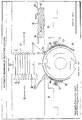
- the attached drawing containing Part Front and Part Plan views illustrates how in a simple form the invention provides near 100% guarding of the rotating cutters of a hand-fed wood-planing machine such as to provide a significant increase in operator safety through shielding the hands of an operator from contact with the cutters. No other known form of safety guard is capable of providing this level of safety.
- the attached drawing does not illustrate in detail the thicknessing function of typical wood-planing machines, as the use of a thicknesser does not detract from the fundamental function and purpose of the invention.
- a piece of wood (marked “Work") is pushed by hand, with or without protective media on the hand(s), from in-feed table (9) to out-feed table (8).
- the height of table (8) is set so that during operation it will be kept on a horizontal plane tangential with the cutting edges of the blades on the rotating cutterblock.
- the height of table (9) will therefore be set for operation below that of table (8) by an amount of at least the minimum believed to be necessary for the removal of undulations and imperfections in the piece of wood.
- the action of this setting during adjustment is such that edge (11) of table (9) moves tangentially to an imaginary circle (whose centre is the centre of the cutterblock) maintaining clearance between itself and the rotating cutter blades.
- the invention allows for this movement of table (9).
- the invention On the Part Front view shown on the attached drawing the invention is illustrated as the pair of spring-loaded assemblies whose component parts are variously labelled as (reading clockwise) (1), (2), (5), (15), (6), (4), (14), (13), (3) and (12).
- the operator in order to plane the piece of wood illustrated will apply a force (P1) downwards with the left hand and a force (P2) forwards with the right hand.
- P1 force downwards with the left hand
- P2 forwards with the right hand.
- the hand applying (P1) In order to maintain a level cut, the hand applying (P1) will not move forward beyond edge (11) until the front end (16) of the wood passes edge (10) on table (8).
- the embodiment of the invention illustrated in the Part Front and Part Plan views comprises and operates as a pair of opposing arrays of spring-loaded arms, which, when the host planing machine is not in use, guard the cutterblock entirely and which, when the host machine is in use, are displaced only in close conformity to the movement and actual position of the piece of wood being planed.
- these arms are curved strips of good strength material guided by guide-pairs (12) and (15).
- the number of these arms will vary according to the width (as viewed from the origin of force (P2)) of the cutterblock and their maximum advisable individual width for safety purposes is presently assessed as no greater than 8mm (eight millimetres).
- work pushes arms (1) backwards. For example work of width up to 8mm wide will tend to displace one arm only, work of between 8mm and 16mm wide will tend to displace two arms, and so on.
- one or more of arms (4) in total width relating to the width of the work, will, guided by guide-pairs (15) and propelled at their ends (14) by springs (6), follow the rear end (17) in close conformity to it until rear end (17) passes over edge (10) of table (8).
- the design safety constraints on the widths of arms (4) are the same as for arms (1) and the width of each arms (4) will be equal in operation to the width of arms (1) and each arm (4) will be directly in line to an opposing arm (1).
- ends (2) of each of arms (1) which have been displaced by the work will be kept by the force (P1) below the upper surface of table (8) in the vicinity of edge (10).
- ends (5) of each of arms (4) above which the work is passing will be kept below the surface of table (9) in the vicinity of edge (11) by force (P1).
- Ends (2) and (5) are constructed from a material or construction of suitably low coefficient of friction to allow easy passage of the work and as seen in the embodiment illustrated have widths of approximately one-half of the arms (1) and (4). This width allows in particular for the withdrawal of ends (2) on arms (1) through slots (7) on edge (10) of table (8).
- slots (7) are often a feature.
- any arms (1) displaced by the work in its passage will be freed from pressure (P1) and, propelled by springs (3), will revert to their former position with their ends (2) in contact with edge (11) of table (9).
- Any of arms (4) which had, propelled by springs (6) of lesser force than springs (3), followed the rear end (17) of the work over the cutterblock, will be returned by the action of the returning arms (1) to the equilibrium position illustrated with their ends (5) adjacent to edge (11).
- planing machines provide a thicknessing facility whereby work may be fed under the cutterblock, as indicated in the illustration, in reverse direction to work fed over the top of the cutterblock. It will be clear that this operation may be carried out whilst arms (1) and (4) remain in either equilibrium or displaced positions and that this could provide potential advantages in diminution of passage of waste through span (x) and dampening of sound.
- the structure of the invention allows readily for the extraction of waste and dust through the incorporation into the invention or its host machine of extraction channels as for example but without limitation, extensions of guide-pairs (12) and (15), employing conventional construction methods.
- Such advantages of masking or enabling the passage of waste or sound will apply also where the cutterblock rotates about a vertical axis, for example in the case of spindle moulding.
- the invention is thus capable of being incorporated fully into the design of new host machines or of being fitted with suitable ancillary fittings or bracketry of conventional construction methods such as to allow tailoring it to the particular individual design features of older host machines.
- the invention is capable of providing substantial dampening of sound caused by the rotating cutterblock and the attached blades.
- the requirement for and advantages of this feature will vary according to the age and design of host machines. It is envisaged that in applications where its abilities to procure sound dampening is seen as the main function as opposed to virtual 100% guarding of the rotating cutterblock, the widths of arms (1) and (4) may be substantially increased, for example with a view to decreasing production costs by minimising the number of individual arms required to be fitted.
- the invention will therefore, regardless of the widths of arms (1) and (4) and regardless of methods used for applying force to these arms (shown in the attached illustration, for purposes of explanation only, as achieved through the use of springs fitted individually to each arm), and regardless of the fine details of its construction and mounting within a host machine, be capable of being employed with advantage in host machines, including special purpose host machines, for reasons including all or any of its capabilities for automatic operation, for provision of very high levels of operator safety, for sound dampening and for waste and dust guidance.
Landscapes
- Engineering & Computer Science (AREA)
- Mechanical Engineering (AREA)
- Life Sciences & Earth Sciences (AREA)
- Wood Science & Technology (AREA)
- Forests & Forestry (AREA)
- Crushing And Pulverization Processes (AREA)
- Milling, Drilling, And Turning Of Wood (AREA)
- Sawing (AREA)
- Debarking, Splitting, And Disintegration Of Timber (AREA)
- Auxiliary Devices For Machine Tools (AREA)
- Cutting Tools, Boring Holders, And Turrets (AREA)
- Turning (AREA)
Claims (9)
- Vorrichtung zum automatischen Schutz von rundlaufenden Schneidwerkzeugen mit Hilfe eines primären und eines sekundären Satzes von gekrümmten Bändern (1, 4), wobei die Primärbänder (1) von ihrer normalen Gleichgewichts-Sicherheitsposition durch das Werkstück (16, 17), das zwei gleichzeitigen senkrechten und waagerechten Kräften entgegen den Umfangskräften ausgesetzt wird, die durch geeignete Kraftquellen (3) auf die Primärbänder (1) aufgebracht werden, über einen kreisförmigen Weg verschoben werden; wenn das Ende des Werkstückes eine Position am Ende des Zustelltisches passiert hat, dann folgen ein oder mehrere entsprechende Sekundärbänder (4), die ihre sonstige Gleichgewichtsposition beibehalten haben, auf Grund der durch das Werkstück (16, 17) aufgebrachten senkrechten Kraft, unter ihren eigenwirkenden Umfangskräften (6) dem Werkstück, wodurch eine sichere Abdeckung der rundlaufenden Schneidwerkzeuge entsteht, bis das Ende des Werkstückes eine Position erreicht hat, in der keine senkrechte Kraft auf die Hauptbänder (1) einwirkt, dadurch gekennzeichnet, daß die Spitzen (2, 5) der beiden Sätze (1, 4) von Bändern aneinander anstoßen, wenn kein Werkstück vorhanden ist; die beiden Sätze jeweils auf einem kreisförmigen Pfad durch Führungspaare (12, 15) geführt werden; die Umfangskraft (3) der Primärbänder (1) größer ist als die entgegengesetzten Umfangskräfte (6) der Sekundärbänder (4); die Spitze (2) der Primärbänder ein gekrümmtes Ende aufweist, das im Ruhezustand an die Kante (11) des Zustelltisches (9) neben den rundlaufenden Schneidwerkzeugen anstößt.
- Vorrichtung zum automatischen Schützen von rundlaufenden Schneidwerkzeugen nach Anspruch 1, wobei die Breite und die Umfangskraftquellen der Primärstreifen von der Konstruktion des zu schützenden Schneidwerkzeuges abhängig sind.
- Vorrichtung zum automatischen Schützen von rundlaufenden Schneidwerkzeugen nach Anspruch 1 und 2, wobei unabhängig vom Breitenverhältnis des Primärbandes zum Werkstück der sichere Schutz der rundlaufenden Schneidwerkzeuge automatisch durch die Sekundärbänder erzielt wird, die auf Grund der durch das Werkstück aufgebrachten senkrechten Kraft und/oder die Bänder erzielt wird, die dem Werkstück folgen.
- Vorrichtung zum automatischen Schützen von rundlaufenden Schneidwerkzeugen nach einem der vorhergehenden Ansprüche, wobei die Rotationsachse der Schneidwerkzeuge in jeder beliebigen räumlichen Ebene liegen kann.
- Vorrichtung zum automatischen Schützen von rundlaufenden Schneidwerkzeugen nach einem der vorhergehenden Ansprüche, wobei bei handbetriebenen Holzhobelmaschinen mit Dickenhobeln die Erfindung genauso gut praktisch ohne Modifikation der Konstruktion der automatischen Schutzvorrichtung anwendbar ist.
- Vorrichtung zum automatischen Schützen von rundlaufenden Schneidwerkzeugen nach einem der vorhergehenden Ansprüche, wobei die Erfindung auf handbetriebene und kraftbetriebene Vorgänge anwendbar ist.
- Vorrichtung zum automatischen Schützen von rundlaufenden Schneidwerkzeugen nach einem der vorhergehenden Ansprüche, wobei die Erfindung das effiziente und sichere Entfernen und/oder Wiedereinsetzen von Schneidklingen und bei handbetriebenen Holzhobelmaschinen und dergleichen das Einstellen des Zustelltisches und des Ausgabetisches auf ihre sicherheitstechnisch geforderten Höhen relativ zu den Schneidklingen nicht unangemessen behindert.
- Vorrichtung zum automatischen Schützen von rundlaufenden Werkzeugen nach einem der vorhergehenden Ansprüche, wobei die Erfindung eine Schallreduzierung verspricht, da sie, in einer vereinfachten Konstruktion, über ihre Schutzfunktion hinaus hauptsächlich aufgrund dieser wichtigen Fähigkeit eingesetzt werden kann.
- Vorrichtung zum automatischen Schützen von rundlaufenden Schneidwerkzeugen nach einem der vorhergehenden Ansprüche, wobei die Erfindung Verbesserungen beim Abführen und/oder Sammeln von Staub, Spänen, Abfall und dergleichen durch effiziente und geregelte Abführung solchen Abfalls gezeigt hat, in diesem Beispiel unabhängig davon, ob der Schneidbetrieb oberhalb (konventionell) oder unterhalb (Dickenhobel) des Schneidwerkzeuges durchgeführt wurde.
Applications Claiming Priority (3)
| Application Number | Priority Date | Filing Date | Title |
|---|---|---|---|
| GB9011723A GB2244319A (en) | 1990-05-25 | 1990-05-25 | Automatic guarding of rotating cutters |
| GB9011723 | 1990-05-25 | ||
| PCT/GB1991/000750 WO1991018724A1 (en) | 1990-05-25 | 1991-05-10 | Automatic guarding of rotating cutters |
Publications (2)
| Publication Number | Publication Date |
|---|---|
| EP0484493A1 EP0484493A1 (de) | 1992-05-13 |
| EP0484493B1 true EP0484493B1 (de) | 1996-08-21 |
Family
ID=10676552
Family Applications (1)
| Application Number | Title | Priority Date | Filing Date |
|---|---|---|---|
| EP91909808A Expired - Lifetime EP0484493B1 (de) | 1990-05-25 | 1991-05-10 | Automatischer schutz von rundlaufenden werkzeugen |
Country Status (6)
| Country | Link |
|---|---|
| EP (1) | EP0484493B1 (de) |
| AT (1) | ATE141543T1 (de) |
| AU (1) | AU7888891A (de) |
| DE (1) | DE69121517D1 (de) |
| GB (1) | GB2244319A (de) |
| WO (1) | WO1991018724A1 (de) |
Families Citing this family (2)
| Publication number | Priority date | Publication date | Assignee | Title |
|---|---|---|---|---|
| DE4417377C1 (de) * | 1994-05-18 | 1995-12-14 | Schweiz Unfallversicherung | Schutzvorrichtung für das Bogenfräsen |
| CN110653658B (zh) * | 2019-08-14 | 2021-05-14 | 湖南煌辉建设有限公司 | 一种环保建筑市政用电力施工设备 |
Family Cites Families (7)
| Publication number | Priority date | Publication date | Assignee | Title |
|---|---|---|---|---|
| FR369448A (fr) * | 1906-09-04 | 1907-01-11 | Victor Gagneur | Protecteur automatique pour machines à dégauchir, à dresser et moulurer le bois ou autres matériaux |
| US1464924A (en) * | 1922-06-20 | 1923-08-14 | William D Drummond | Saw guard |
| US1829313A (en) * | 1930-12-05 | 1931-10-27 | Tompkins Jesse James | Woodworking machine |
| FR1106176A (fr) * | 1954-08-03 | 1955-12-13 | Sncf | Dispositif de protection pour machines à bois |
| CH426210A (de) * | 1962-05-12 | 1966-12-15 | Technoimpex Magyar Gepipari Ku | Schutzvorrichtung für Abrichtmaschinen |
| DE2107139A1 (de) * | 1970-10-22 | 1972-04-27 | Shimohira Seisakusho, Tokio | Sicherheitsvorrichtung fur elektrische Hobeibanke |
| DE8602800U1 (de) * | 1986-02-04 | 1986-03-27 | Mafell Maschinenfabrik Rudolf Mey Gmbh & Co Kg, 78727 Oberndorf | Dicken- und Abrichthobelmaschine |
-
1990
- 1990-05-25 GB GB9011723A patent/GB2244319A/en not_active Withdrawn
-
1991
- 1991-05-10 AU AU78888/91A patent/AU7888891A/en not_active Abandoned
- 1991-05-10 DE DE69121517T patent/DE69121517D1/de not_active Expired - Lifetime
- 1991-05-10 EP EP91909808A patent/EP0484493B1/de not_active Expired - Lifetime
- 1991-05-10 WO PCT/GB1991/000750 patent/WO1991018724A1/en not_active Ceased
- 1991-05-10 AT AT91909808T patent/ATE141543T1/de not_active IP Right Cessation
Also Published As
| Publication number | Publication date |
|---|---|
| ATE141543T1 (de) | 1996-09-15 |
| GB9011723D0 (en) | 1990-07-18 |
| GB2244319A (en) | 1991-11-27 |
| EP0484493A1 (de) | 1992-05-13 |
| WO1991018724A1 (en) | 1991-12-12 |
| DE69121517D1 (de) | 1996-09-26 |
| AU7888891A (en) | 1991-12-31 |
Similar Documents
| Publication | Publication Date | Title |
|---|---|---|
| CA1224702A (en) | Method of guiding saw blades and device for carrying out the method | |
| CA2210431A1 (en) | Chipper with detachable facing knives | |
| ES515714A0 (es) | "metodo y maquina para la realizacion automatica de operaciones de rectificacion". | |
| CA2123043A1 (en) | Method and Device for Resharpening Knives Used in Cutting Machines | |
| EP0484493B1 (de) | Automatischer schutz von rundlaufenden werkzeugen | |
| US4583893A (en) | Reprofiling device for rails through continuous milling | |
| DK0598079T3 (da) | Beskyttelseshætte til træfræsemaskine | |
| DE69934335D1 (de) | Schärfen eines schneidwerkzeuges mit einer wellenförmigen schneide | |
| DE3664115D1 (en) | Machine tool for machining the ends of work pieces | |
| CA1234985A (en) | Device for sharpening circular knives | |
| GB1031675A (en) | Improvements in or relating to planing or facing machines | |
| US4987704A (en) | Plunge jointer for planer knives | |
| DE3365274D1 (en) | Milling machine | |
| US2895518A (en) | Shaper guard with auxiliary finger protectors | |
| SE8105688L (sv) | Instellbar skyddsanordning for verktygsmaskiner | |
| US20040042862A1 (en) | Guide for rotary cutter | |
| FR2414391A1 (fr) | Dispositif pour trancher les materiaux tendres | |
| SU1759625A1 (ru) | Ограждение фрезерного станка | |
| US3841175A (en) | Method and apparatus for modifying lock keys | |
| ES2027118A6 (es) | Dispositivo protector de geometria variable para maquinas de conformar madera. | |
| RU1773720C (ru) | Универсальный деревообрабатывающий станок | |
| RU2044630C1 (ru) | Универсальный станок | |
| RU2026171C1 (ru) | Универсальный настольный деревообрабатывающий станок | |
| KR20250062212A (ko) | 안전커버를 구비한 그루브 홈가공 장치 | |
| RU2130827C1 (ru) | Универсальный деревообрабатывающий станок |
Legal Events
| Date | Code | Title | Description |
|---|---|---|---|
| PUAI | Public reference made under article 153(3) epc to a published international application that has entered the european phase |
Free format text: ORIGINAL CODE: 0009012 |
|
| AK | Designated contracting states |
Kind code of ref document: A1 Designated state(s): AT BE CH DE DK ES FR GB IT LI NL SE |
|
| 17P | Request for examination filed |
Effective date: 19920826 |
|
| 17Q | First examination report despatched |
Effective date: 19940706 |
|
| GRAH | Despatch of communication of intention to grant a patent |
Free format text: ORIGINAL CODE: EPIDOS IGRA |
|
| RAP3 | Party data changed (applicant data changed or rights of an application transferred) |
Owner name: KARP, STEFAN |
|
| GRAA | (expected) grant |
Free format text: ORIGINAL CODE: 0009210 |
|
| AK | Designated contracting states |
Kind code of ref document: B1 Designated state(s): AT BE CH DE DK ES FR GB IT LI NL SE |
|
| PG25 | Lapsed in a contracting state [announced via postgrant information from national office to epo] |
Ref country code: IT Free format text: LAPSE BECAUSE OF FAILURE TO SUBMIT A TRANSLATION OF THE DESCRIPTION OR TO PAY THE FEE WITHIN THE PRE;WARNING: LAPSES OF ITALIAN PATENTS WITH EFFECTIVE DATE BEFORE 2007 MAY HAVE OCCURRED AT ANY TIME BEFORE 2007. THE CORRECT EFFECTIVE DATE MAY BE DIFFERENT FROM THE ONE RECORDED.SCRIBED TIME-LIMIT Effective date: 19960821 Ref country code: CH Effective date: 19960821 Ref country code: NL Free format text: LAPSE BECAUSE OF FAILURE TO SUBMIT A TRANSLATION OF THE DESCRIPTION OR TO PAY THE FEE WITHIN THE PRESCRIBED TIME-LIMIT Effective date: 19960821 Ref country code: LI Effective date: 19960821 Ref country code: BE Effective date: 19960821 Ref country code: DK Effective date: 19960821 Ref country code: AT Effective date: 19960821 Ref country code: ES Free format text: THE PATENT HAS BEEN ANNULLED BY A DECISION OF A NATIONAL AUTHORITY Effective date: 19960821 Ref country code: FR Effective date: 19960821 |
|
| REF | Corresponds to: |
Ref document number: 141543 Country of ref document: AT Date of ref document: 19960915 Kind code of ref document: T |
|
| REF | Corresponds to: |
Ref document number: 69121517 Country of ref document: DE Date of ref document: 19960926 |
|
| PG25 | Lapsed in a contracting state [announced via postgrant information from national office to epo] |
Ref country code: SE Effective date: 19961121 |
|
| PG25 | Lapsed in a contracting state [announced via postgrant information from national office to epo] |
Ref country code: DE Effective date: 19961122 |
|
| EN | Fr: translation not filed | ||
| NLV1 | Nl: lapsed or annulled due to failure to fulfill the requirements of art. 29p and 29m of the patents act | ||
| REG | Reference to a national code |
Ref country code: CH Ref legal event code: PL |
|
| PLBE | No opposition filed within time limit |
Free format text: ORIGINAL CODE: 0009261 |
|
| STAA | Information on the status of an ep patent application or granted ep patent |
Free format text: STATUS: NO OPPOSITION FILED WITHIN TIME LIMIT |
|
| 26N | No opposition filed | ||
| PGFP | Annual fee paid to national office [announced via postgrant information from national office to epo] |
Ref country code: GB Payment date: 20010516 Year of fee payment: 11 |
|
| REG | Reference to a national code |
Ref country code: GB Ref legal event code: IF02 |
|
| PG25 | Lapsed in a contracting state [announced via postgrant information from national office to epo] |
Ref country code: GB Free format text: LAPSE BECAUSE OF NON-PAYMENT OF DUE FEES Effective date: 20020510 |
|
| GBPC | Gb: european patent ceased through non-payment of renewal fee |
Effective date: 20020510 |