EP0484549B1 - Verfahren zum steuern des arbeitszyklus einer spritzgiessmaschine - Google Patents
Verfahren zum steuern des arbeitszyklus einer spritzgiessmaschine Download PDFInfo
- Publication number
- EP0484549B1 EP0484549B1 EP91909356A EP91909356A EP0484549B1 EP 0484549 B1 EP0484549 B1 EP 0484549B1 EP 91909356 A EP91909356 A EP 91909356A EP 91909356 A EP91909356 A EP 91909356A EP 0484549 B1 EP0484549 B1 EP 0484549B1
- Authority
- EP
- European Patent Office
- Prior art keywords
- synthetic resin
- screw
- plasticized synthetic
- injection
- dwelling
- Prior art date
- Legal status (The legal status is an assumption and is not a legal conclusion. Google has not performed a legal analysis and makes no representation as to the accuracy of the status listed.)
- Expired - Lifetime
Links
- 238000000034 method Methods 0.000 title claims abstract description 79
- 238000000465 moulding Methods 0.000 title claims abstract description 37
- 238000001746 injection moulding Methods 0.000 title abstract description 4
- 229920003002 synthetic resin Polymers 0.000 claims abstract description 93
- 239000000057 synthetic resin Substances 0.000 claims abstract description 93
- 238000002347 injection Methods 0.000 claims abstract description 60
- 239000007924 injection Substances 0.000 claims abstract description 60
- 229920005989 resin Polymers 0.000 claims description 33
- 239000011347 resin Substances 0.000 claims description 33
- 238000005429 filling process Methods 0.000 claims description 7
- 238000003825 pressing Methods 0.000 claims description 6
- 230000000903 blocking effect Effects 0.000 claims 1
- 239000000463 material Substances 0.000 description 5
- 238000007789 sealing Methods 0.000 description 4
- 239000008188 pellet Substances 0.000 description 2
- 238000004904 shortening Methods 0.000 description 2
- 238000001816 cooling Methods 0.000 description 1
- 238000010586 diagram Methods 0.000 description 1
- 238000004898 kneading Methods 0.000 description 1
- 238000004519 manufacturing process Methods 0.000 description 1
- 239000000155 melt Substances 0.000 description 1
- 238000002844 melting Methods 0.000 description 1
- 230000008018 melting Effects 0.000 description 1
- 239000000243 solution Substances 0.000 description 1
Images

Classifications
-
- B—PERFORMING OPERATIONS; TRANSPORTING
- B29—WORKING OF PLASTICS; WORKING OF SUBSTANCES IN A PLASTIC STATE IN GENERAL
- B29C—SHAPING OR JOINING OF PLASTICS; SHAPING OF MATERIAL IN A PLASTIC STATE, NOT OTHERWISE PROVIDED FOR; AFTER-TREATMENT OF THE SHAPED PRODUCTS, e.g. REPAIRING
- B29C45/00—Injection moulding, i.e. forcing the required volume of moulding material through a nozzle into a closed mould; Apparatus therefor
- B29C45/17—Component parts, details or accessories; Auxiliary operations
- B29C45/76—Measuring, controlling or regulating
- B29C45/77—Measuring, controlling or regulating of velocity or pressure of moulding material
-
- B—PERFORMING OPERATIONS; TRANSPORTING
- B29—WORKING OF PLASTICS; WORKING OF SUBSTANCES IN A PLASTIC STATE IN GENERAL
- B29C—SHAPING OR JOINING OF PLASTICS; SHAPING OF MATERIAL IN A PLASTIC STATE, NOT OTHERWISE PROVIDED FOR; AFTER-TREATMENT OF THE SHAPED PRODUCTS, e.g. REPAIRING
- B29C45/00—Injection moulding, i.e. forcing the required volume of moulding material through a nozzle into a closed mould; Apparatus therefor
- B29C45/17—Component parts, details or accessories; Auxiliary operations
- B29C45/46—Means for plasticising or homogenising the moulding material or forcing it into the mould
- B29C45/57—Exerting after-pressure on the moulding material
-
- B—PERFORMING OPERATIONS; TRANSPORTING
- B29—WORKING OF PLASTICS; WORKING OF SUBSTANCES IN A PLASTIC STATE IN GENERAL
- B29C—SHAPING OR JOINING OF PLASTICS; SHAPING OF MATERIAL IN A PLASTIC STATE, NOT OTHERWISE PROVIDED FOR; AFTER-TREATMENT OF THE SHAPED PRODUCTS, e.g. REPAIRING
- B29C45/00—Injection moulding, i.e. forcing the required volume of moulding material through a nozzle into a closed mould; Apparatus therefor
- B29C45/17—Component parts, details or accessories; Auxiliary operations
- B29C45/46—Means for plasticising or homogenising the moulding material or forcing it into the mould
- B29C45/47—Means for plasticising or homogenising the moulding material or forcing it into the mould using screws
- B29C45/50—Axially movable screw
-
- B—PERFORMING OPERATIONS; TRANSPORTING
- B29—WORKING OF PLASTICS; WORKING OF SUBSTANCES IN A PLASTIC STATE IN GENERAL
- B29C—SHAPING OR JOINING OF PLASTICS; SHAPING OF MATERIAL IN A PLASTIC STATE, NOT OTHERWISE PROVIDED FOR; AFTER-TREATMENT OF THE SHAPED PRODUCTS, e.g. REPAIRING
- B29C45/00—Injection moulding, i.e. forcing the required volume of moulding material through a nozzle into a closed mould; Apparatus therefor
- B29C45/17—Component parts, details or accessories; Auxiliary operations
- B29C45/76—Measuring, controlling or regulating
-
- B—PERFORMING OPERATIONS; TRANSPORTING
- B29—WORKING OF PLASTICS; WORKING OF SUBSTANCES IN A PLASTIC STATE IN GENERAL
- B29C—SHAPING OR JOINING OF PLASTICS; SHAPING OF MATERIAL IN A PLASTIC STATE, NOT OTHERWISE PROVIDED FOR; AFTER-TREATMENT OF THE SHAPED PRODUCTS, e.g. REPAIRING
- B29C45/00—Injection moulding, i.e. forcing the required volume of moulding material through a nozzle into a closed mould; Apparatus therefor
- B29C45/17—Component parts, details or accessories; Auxiliary operations
- B29C45/46—Means for plasticising or homogenising the moulding material or forcing it into the mould
- B29C45/47—Means for plasticising or homogenising the moulding material or forcing it into the mould using screws
- B29C45/50—Axially movable screw
- B29C2045/5096—Axially movable screw decompression of the moulding material by retraction or opposite rotation of the screw
Definitions
- the invention relates to a molding cycle control method for an injection molder according to the preamble of claim 1.
- Injection molding of plasticized synthetic resin conducted by the use of an injection molder has a problem in that it is difficult to keep the quality of molded products constant by making up the shrinkage of the plasticized synthetic resin in cooling and setting in the cavity of the mold.
- various control methods for the injection process have been proposed.
- the gate-sealing is a function occurring inside the mold, so that it is quite difficult to detect precisely when gate sealing occurs. Furthermore, the time when the gate-sealing occurs varies depending on subtle changes of temperatures of the mold and the plasticized synthetic resin, so that the time the screw or the plunger is locked must be set excessively long to ensure completion of the gate sealing. Also, locking of the screw or the plunger needs a feed-back control device, resulting in requiring an expensive injection molder. Hence, it further leads to a problem of a low productivity due to a longer locking time and a high cost of production due to the use of a complicated control device.
- the conventional control method as above-mentioned supplies a corresponding volumetric amount of material to the shrinkage from the molded product itself by locking the screw or the plunger until the gate is sealed in the dwelling process to prevent a flow of the plasticized synthetic resin in the gate so as to release the pressure of the resin which has been compressed by the filling operation.
- the shrinkage can be made up and a molded product of a fixed volume corresponding to an internal volume of the cavity can be provided.
- the plasticized synthetic resin has a compressibility, its density changes depending on the pressure and temperatures, so that it is hard to keep a constant weight of a molded products.
- a method for controlling injection of a plastic injection molder is further known from the JP-A-1-22562.
- This method is provided with a pre-injection process between a molton plastic filling process and an injection process.
- a nozzle provided between an feed cylinder and a mold is closed in order to apply a predetermined pressure to the molten plastic in the cylinder by a plunger arranged in it.
- the plunger is moved forwards to a position, at which a non-return valve is sealed.
- An injection starting position can thereby precisely detected, at which the predetermined pressure of the molten plastic in the cylinder is achieved and a blackflow of the molten plastic is prevented by the sealed non-return valve.
- An object of the invention is to provide a molding cycle control method for an injection molder which method can shorten the time required for each molding cycle without using a complicated device and keep the weight of the molded products constant.
- the molding cycle control method for an injection molder according to the invention is characterized by the features of claim 1.
- a check valve be provided at the screw which closes during the pre-injection pressing process to prevent a flow of the plasticized synthetic resin between the flow passage opening and closing mechanism and the check valve in the direction of the backward movement of the screw.
- a predetermined amount of the plasticized synthetic resin to be filled in the cavity may be detected from the screw's specific positional values or the plasticized synthetic resin pressure values placed in the cylinder or in the cavity, or also from a predetermined travel distance of the screw corresponding to its value, respectively, from a point where the screw is positioned immediately before the injection operation.
- the predetermined amount of the plasticized synthetic resin may be represented by the following formula with a weight value G as follows.
- V I is a specific volume value of plasticized synthetic resin on the forward movement side of the front end of the screw in the cylinder immediately before the injection operation
- V H is a specific volume value of the plasticized synthetic resin on the forward movement side of the front end of the screw in the cylinder during the dwelling operation
- V is a volume value of the plasticized synthetic resin on the forward movement side of the front end of the screw in the cylinder immediately before the injection process
- A is the internal sectional area of the cylinder
- X is the travel distance of the screw from its position immediately before the injection to its position during the dwelling operation.
- the flow passage opening and closing mechanism is closed while a predetermined pushing force is being applied to the screw.
- the suck-back process is conducted while the plasticized synthetic resin placed in the gate of the mold is solidified and the flow of the plasticized synthetic resin in the gate is blocked.
- the suck-back process may be carried out at any stage during the measuring process or after the completion thereof.
- the plasticized synthetic resin in the mold and the plasticized synthetic resin in the screw do not affect each other when the flow passage opening and closing mechanism is closed, so that the separate processes may be conducted simultaneously.
- the flow passage opening and closing mechanism is closed during the dwelling process while a predetermined pushing force is applied to the screw for generating dwelling pressure for compensating for the shrinkage of the cooled plasticized synthetic resin
- a residual dwelling pressure is created on the mold side of the mechanism where dwelling is then continued while simultaneously, measuring for a next molding cycle can be immediately conducted on the screw side of the mechanism, thereby shortening the time for each molding cycle.
- the flow passage opening and closing mechanism as well as the check valve provided at the screw are closed and the plasticized synthetic resin in the cylinder does not flow back, so that the pressure value of the plasticized synthetic resin can have a definite predetermined value immediately before the injection operation.
- the resin pressure value of the resin during dwelling process can be set to a definite predetermined value.
- the positional value of the screw, the plasticized synthetic resin pressures in the cylinder or in the cavity, or the screw's predetermined travel distance from its position where the screw is positioned immediately before the injection may be detected to obtain a predetermined amount of the plasticized synthetic resin to be injected and filled in the cavity.
- weight value of the plasticized synthetic resin to be injected and filled in the cavity can be obtained to control the injection molder to provide molded products of a constant weight.
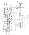
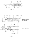
- Figs. 1 through 4 are explanatory drawings showing preferable examples of the molding cycle control method of the injection molder according to the present invention.
- Fig. 1 shows a profile of the injection molder, wherein an injection molder 11 is connected to a mold 10 for preparing a molded product through a nozzle part 12.
- a screw 18 which melts and kneads resin pellets of the plastifiable synthetic resin material fed from a material hopper 14, and measures the melted and plasticized resin to inject and fill it into a cavity 17 of the mold 10 through a flow passage 15 bored in the nozzle part 12 and a gate 16 of the mold 10.
- Rotation of the screw 18 for melting and kneading the material resin pellets is controlled by operating an electromagnetic flow valve 19, an electromagnetic pressure valve 20 and a switch valve 21 through a controller 22 to supply and discharge pressure oil from a pressure oil source 23 to a screw rotating motor 24 through a piping 25a.
- the screw 18 and the screw rotating motor 24 are mounted on a base 26 which is driven to the right and left side in the drawing by means of the pressure oil which is supplied and discharged to a hydraulic piston device 27 from the pressure oil source 23 through pipings 25b and 25c by controlling the electromagnetic flow valve 19, electromagnetic pressure valve 20 and switch valve 21 with the controller 22.
- forward and backward movement of the screw 18 with respect to the nozzle part 12 for measuring of the plasticized synthetic resin to be injected and injecting and filling of the measured plasticized synthetic resin into the cavity 17 of the mold 10, and the application of a predetermined pushing force to the screw 18 for providing a predetermined pressure of the plasticized synthetic resin in the cylinder 13 are carried out through the base 26 by supplying and exhausting pressure oil to the hydraulic piston device 27.
- a screw position detector 28 which detects positional values of the screw 18 is disposed on the base 26. The detected positional values are transmitted to the controller 22 and an arithmetical unit 29 for determining the weight value of filled plasticized synthetic resin and the like.
- arithmetical unit 29 To the arithmetical unit 29 are also transmitted the temperature values from a resin temperature detector 30 which detects the temperature of the plasticized synthetic resin placed in the cylinder 13, the resin pressure values from a resin pressure detector 31 which detects the resin pressure of the plasticized synthetic resin placed in the cylinder 13 and the cavity resin pressure values from a cavity pressure detector 32 which detects the resin pressure of the plasticized synthetic resin placed in the cavity 17 of the mold 10.
- a closing valve 33 which constitutes the flow passage 15 opening and closing mechanism of the present invention and blocks the flow of the melted plasticized synthetic resin. Opening and closing of the closing valve 33 is accomplished through the lever 35 by controlling an electromagnetic drive device 34.
- a ring-like shaped slidable valve member 39 which is axially movable forward and backward is inserted between a conical front end 36 of the screw 18 and a flange projection 38 at the end of spiral 37.
- the ring-like shaped slidable valve member 39 is pressed and contacted to the flange projection 38 when the pressure of the plasticized synthetic resin at the leftside of the drawing, in turn, at the front end side of the screw 18 becomes higher, so that it prevents the plasticized synthetic resin from flowing back to the right side in the drawing.
- a check valve 40 consists of the flange projection 38 and ring-like shaped slidable valve member 39.
- a screw positional value S I at the time detecting P I is detected by the screw position detector 28 and transmitted to the controller 22 and the arithmetical unit 29, and the temperature values T I of the plasticized synthetic resin detected by the resin temperature detector 30 and is the transmitted to the arithmetical unit 29.
- Specific values of the resin pressure value P I , screw positional value S I and temperature value T I are supplied, as detected values obtained immediately before the injection operation, to the arithmetical unit 29 for its determination of a weight value G (described later) of the plasticized synthetic resin to be filled in the cavity 17. (See Fig. 4)
- the screw 18 is moved forward to fill the plasticized synthetic resin into the cavity 17 of the mold 10 followed by applying a predetermined pushing force to the screw 18 to give a dwelling pressure to the plasticized synthetic resin filled in the cavity 17. While a predetermined pushing force is applied to the screw 18, the closing valve 33 is closed to allow resin pressure in the cylinder 13 to be at a definite predetermined resin pressure value P H which is detected by the resin pressure detector 31 and transmitted to the arithmetical unit 29.
- the screw positional value S H detected by the screw position detector 28 is transmitted to the controller 22 and the arithmetical unit 29, and the temperature value T H of the plasticized synthetic resin detected by the resin temperature detector 30 is transmitted to the arithmetical unit 29.
- Specific values of the resin pressure value P H , screw positional value S H and temperature value T H are supplied, as detected values obtained in the dwelling operation, to the arithmetical unit 29 in order to be applied in the determination of a weight value G (described later) of the plasticized synthetic resin to be filled in the cavity 17. (See Fig. 4)
- the screw 18 While the closing valve 33 is closed, as continued from the previous process, to block the plasticized synthetic resin from flowing, the screw 18 is rotated and moved back to measure a predetermined ratio of the plasticized synthetic resin of a predetermined amount of the same for a next molding cycle.
- the closing valve 33 was closed while a predetermined pushing force was being applied to the screw 18, so that the plasticized synthetic resin remaining in the cavity 17 has residual dwelling pressure even after the closing valve 33 is closed, which is the same as that applied by the screw 18 due to the predetermined pushing force to give dwelling pressure to the plasticized synthetic resin.
- the present first half of the measuring process carries out the dwelling operation through residual dwelling pressure on the mold 10 side of the valve 33 simultaneously with the measuring operation on the screw 18 side of the valve 33.
- the closing valve 33 is opened and due to the screw 18 moving back, the pressure of plasticized synthetic resin between the gate 16 of mold 10 and the front end of the screw 18 at its forward movement side is lowered, so that leakage of the plasticized synthetic resin placed between the nozzle part 12 and the mold 10 or from the parting line thereof is prevented.
- the screw 18 While the closing valve 33 is closed to block the plasticized synthetic resin from flowing, the screw 18 is rotated and moved back to measure a remaining portion of the plasticized synthetic resin in addition to that measured in the previous (3) measuring process to reach the predetermined amount of plasticized synthetic resin for a next molding cycle.
- the closing valve 33 is closed while a predetermined pushing force is applied to the screw 18 in the dwelling process, so that movement of the screw 18 does not affect the mold 10 side.
- the mold 10 side has a residual dwelling pressure with the dwelling operation being continued, and the screw 18 side is able to carry out measuring for a next molding cycle immediately after the closing of the closing valve 33.
- the dwelling process and the measuring process run simultaneously, thereby shortening the time required for each molding cycle.
- Both the closing valve 33 and the check valve 40 are closed immediately before the injection (immediately after pre-injection pressing) and during dwelling operation. Resin pressure of the plasticized synthetic resin placed between the closing valve 33 and the check valve 40 with the screw 18 being so positioned in these circumstances indicates definite predetermined values.
- specific volume value of the plasticized synthetic resin is obtained from a known resin properties relation formula, such as PVT relation formula (resin pressure value - resin specific volume value - resin temperature values) by the use of the above values of the screw positional values S I , S H , resin pressure values P I , P H and resin temperature values T I , T H , and further, the weight value G of plasticized synthetic resin to be filled in the cavity 17 is obtained through an operation based on the following formula (1).
- PVT relation formula resin pressure value - resin specific volume value - resin temperature values
- V I is a specific volume value of plasticized synthetic resin on the forward movement side of the front end of the screw 18 in the cylinder 13 immediately before the injection operation
- V H is a specific volume value of the plasticized synthetic resin on the forward movement side of the front end of the screw 18 in the cylinder 13 during the dwelling operation
- A: is the internal sectional area of the cylinder
- the internal sectional area A of the cylinder in the formula (1) is obtained from the design value of the injection molder 11, and the volume value V of the plasticized synthetic resin placed the front end of the screw 18 on the forward movement side in the cylinder 13 immediately before the injection can be obtained from the cylinder internal sectional area A and the screw positional value S I through the operation by the arithmetical unit 29.
- molded products of a stable quality can be provided by controlling the injection molder on the basis of a traveling distance X of the screw 18 which value is obtained through the operation of using the PVT relation formula (1) to form a molded product with a target weight value G.
- the weight value G of plasticized synthetic resin to be filled in the cavity 17 of the mold 10 is obtained through the operation.
- the injection molder may be controlled by detecting the screw positional values, the resin pressure value of plasticized synthetic resin placed in the cylinder 13 or in the cavity 17, corresponding to the weight value G, respectively.
- the measuring process is divided into two with respect to the time when the gate 16 is sealed, so that the first half of the measuring process includes the suck-back process.
- the suck-back process may be conducted after the completion of the measuring process depending on the kinds of the plasticized synthetic resin to be used, resin pressure values, shapes of the mold 10, volumes of the cavity 17 and the like.
- the dwelling process and the measuring of the plasticized synthetic resin for a next molding cycle are carried out simultaneously, so that the time required for each molding cycle can be shortened. Also, even when the molding condition changes due to the external disturbances or the like, the weight values of molded products can be kept constant, thereby contributing to the improvement of the productivity and the quality of products.
Landscapes
- Engineering & Computer Science (AREA)
- Manufacturing & Machinery (AREA)
- Mechanical Engineering (AREA)
- Injection Moulding Of Plastics Or The Like (AREA)
Claims (9)
- Gießzyklus-Steuerverfahren für eine Spritzgießvorrichtung (11) mit einem Zylinder (13) mit einer darin angeordneten Spindel (18) und einem Strömungskanal- (15) Öffnungs- und Schließmechanismus (33), welcher zwischen dem Zylinder (13) der Spritzgießvorrichtung (11) und einem Einlaß (16) einer Form (10) angeordnet ist, wobei die Form (10) einen Formhohlraum (17) aufweist, und der Öffnungs- und Schließmechanismus (33) zum Blockieren der Strömung eines aushärtbaren Kunstharzes zwischen dem Inneren des Zylinders (13) und dem Hohlraum (17) der Form (10) vorgesehen ist, mit dem Verfahrensschritt:(a) einem Vor-Einspritz-Preßvorgang, wobei nachdem der Kunstharz ausgehärtet und dosiert wurde, wobei der Strömungskanal-Öffnungs- und Schließmechanismus (33) geschlossen ist, um ein Ausströmen von plastifiziertem Kunstharz zu verhindern, eine vorbestimmte Druckkraft auf die Spindel (18) aufgebracht wird, um den Harzdruck-Wert im Inneren des Zylinders (13) auf einen vorbestimmten Wert einzustellen, wobei das Verfahren gekennzeichnet ist, durch die Verfahrensschritte(b) einen Einfüll- und einem Nachpreßvorgang, wobei bei dem Einfüllvorgang der Strömungskanal-Öffnungs- und Schließmechanismus (33) geöffnet ist, um eine Strömung des aushärtbaren Kunstharzes zu erlauben, wobei die Spindel (18) vorwärts bewegt wird, um das aushärtbare Kunstharz in den Hohlraum (17) der Form (10) einzuspritzen und einzufüllen, und wobei bei dem auf den Einfüllvorgang folgenden Nachpreßvorgang eine vorbestimmte Druckkraft auf die Spindel (18) ausgeübt wird, während der Strömungskanal-Öffnungs- und Schließmechanismus (33) geschlossen ist, wobei der Einfüll- und Nachpreßvorgang durchgeführt werden, um eine vorbestimmte Menge von aushärtbarem Kunstharz in den Hohlraum (17) einzufüllen,(c) einem Dosiervorgang, bei welchem der Strömungskanal-Öffnungs- und Schließmechanismus (33) geschlossen ist, um die Strömung des aushärtbaren Kunstharzes abzusperren, wobei die Spindel (18) gedreht wird und nach hinten bewegt wird, um eine vorbestimmte Menge des aushärtbaren Kunstharzes für den nächsten Gießzyklus zu dosieren, und(d) einem Rücksaugvorgang, bei welchem der Strömungskanal-Öffnungs- und Schließmechanismus (33) geöffnet ist, um ein Strömen des aushärtbaren Kunstharzes zu erlauben, wobei die Spindel (18) nach hinten bewegt wird, um den Druck in dem aushärtbaren Kunstharz zu verringern, welches zwischen dem Einlaß (16) der Form (10) und dem vorderen Ende der Spindel (18) auf deren Vorwärtsbewegungsseite angeordnet ist.
- Gießzyklus-Steuerverfahren für eine Spritzgießvorrichtung (11) nach Anspruch 1, wobei bei dem Preßvorgang vor dem Einspritzvorgang ein an die Spindel (18) montiertes Rückschlagventil (40) geschlossen ist, um eine Strömung des sich zwischen dem Strömungskanal- (15) Öffnungs- und Schließmechanismus (33) und dem Rückschlagventil (40) befindenden, aushärtbaren Kunstharzes in der Rückwärtsbewegungsrichtung der Spindel (18) zu verhindern.
- Gießzyklus-Steuerverfahren für eine Spritzgießvorrichtung nach den Ansprüchen 1 oder 2, wobei während des Nachpreß- und Einfüllvorgangs eine vorbestimmte Menge von aushärtbarem Kunstharz, welches in den Hohlraum (17) einzufüllen ist, aufgrund des Positionswertes der Spindel (18) oder des Druckwertes des sich in dem Zylinder (13) oder dem Hohlraum (17) befindenden, aushärtbaren Kunstharzes ermittelt wird.
- Gießzyklus-Steuerverfahren für eine Spritzgießvorrichtung (11) nach den Ansprüchen 1 oder 2, wobei während des Nachpreß- und Einfüllvorgangs eine vorbestimmte Menge von aushärtbarem Kunstharz, welches in den Hohlraum (17) einzufüllen ist, aufgrund einer vorbestimmten, zurückzulegenden Wegstrecke der Spindel (18) ausgehend von einer Stellung der Spindel (18) bestimmt wird, in welcher sie sich unmittelbar vor dem Einspritzvorgang befindet.
- Gießzyklus-Steuerverfahren für eine Spritzgießvorrichtung (11) nach den Patentansprüchen 1 oder 2, wobei eine vorbestimmte Menge von aushärtbarem Kunstharz, welches in den Hohlraum (17) einzufügen ist, während des Nachpreß- und Einfüllvorgangs durch folgende Formel mit einem Gewichtswert G repräsentiert wird:

wobei:
VI ein spezifischer Volumenwert des aushärtbaren Kunstharzes ist, welches auf der Vorwärtsbewegungsseite des vorderen Endes der Spindel (18) in dem Zylinder (13) unmittelbar vor dem Einspritzvorgang angeordnet ist;
VH ein spezifischer Volumenwert des aushärtbaren Kunstharzes ist, welches auf der Vorwärtsbewegungsseite des vorderen Endes der Spindel (18) in dem Zylinder (13) während des Nachpressvorgangs angeordnet ist;
V ein Volumen des aushärtbaren Kunstharzes ist, welches auf der Vorwärtsbewegungsseite des vorderen Endes der Spindel (18) in dem Zylinder (13) unmittelbar vor dem Einspritzvorgang angeordnet ist;
A eine innere Querschnittsfläche des Zylinders (13) ist; und
X eine Bewegungs-Wegstrecke der Spindel (18) von einer Stelle vor dem Einspritzvorgang bis zu dem Nachpreßvorgang ist. - Gießzyklus-Steuerverfahren für eine Spritzgießvorrichtung (11) nach einem der Ansprüche 1 bis 5, wobei während des Nachpreßvorgangs der Strömungskanal- (15) Öffnungs- und Schließmechanismus (33) in einem Zustand geschlossen wird, in welchem eine vorbestimmte Druckkraft auf die Spindel (18) ausgeübt wird.
- Gießzyklus-Steuerverfahren für eine Spritzgießvorrichtung (11) nach einem der Ansprüche 1 bis 6, wobei der Rücksaugvorgang in einem Zustand ausgeführt wird, in welchem das aushärtbare Kunstharz, welches in dem Einlaß (16) der Form (10) angeordnet ist, ausgehärtet ist und eine Strömung in dem Einlaß (16) blockiert.
- Gießzyklus-Steuerverfahren für eine Spritzgießvorrichtung (11) nach einem der Ansprüche 1 bis 7, wobei der Rücksaugvorgang während des Dosiervorgangs ausgeführt wird.
- Gießzyklus-Steuerverfahren für eine Spritzgießvorrichtung (11) nach einem der Ansprüche 1 bis 7, wobei nach der Beendigung des Dosiervorgangs der Strömungskanal- (15) Öffnungs- und Schließmechanismus (33) geöffnet ist und der Rücksaugvorgang durchgeführt wird.
Applications Claiming Priority (3)
| Application Number | Priority Date | Filing Date | Title |
|---|---|---|---|
| JP134763/90 | 1990-05-24 | ||
| JP2134763A JPH0822562B2 (ja) | 1990-05-24 | 1990-05-24 | 射出成形機のサイクル制御方法 |
| PCT/JP1991/000637 WO1991017879A1 (fr) | 1990-05-24 | 1991-05-15 | Procede pour regler le cycle de moulage d'une machine de moulage par injection |
Publications (3)
| Publication Number | Publication Date |
|---|---|
| EP0484549A1 EP0484549A1 (de) | 1992-05-13 |
| EP0484549A4 EP0484549A4 (en) | 1992-07-08 |
| EP0484549B1 true EP0484549B1 (de) | 1994-10-12 |
Family
ID=15135991
Family Applications (1)
| Application Number | Title | Priority Date | Filing Date |
|---|---|---|---|
| EP91909356A Expired - Lifetime EP0484549B1 (de) | 1990-05-24 | 1991-05-15 | Verfahren zum steuern des arbeitszyklus einer spritzgiessmaschine |
Country Status (6)
| Country | Link |
|---|---|
| US (1) | US5266247A (de) |
| EP (1) | EP0484549B1 (de) |
| JP (1) | JPH0822562B2 (de) |
| KR (1) | KR100189347B1 (de) |
| DE (1) | DE69104587T2 (de) |
| WO (1) | WO1991017879A1 (de) |
Families Citing this family (22)
| Publication number | Priority date | Publication date | Assignee | Title |
|---|---|---|---|---|
| JPH04336222A (ja) * | 1991-05-14 | 1992-11-24 | Sumitomo Jukikai Plast Mach Kk | 射出成形機のノズル内樹脂圧による制御方法 |
| US5370518A (en) * | 1992-01-29 | 1994-12-06 | Kabushiki Kaisha Komatsu Seisakusho | Apparatus for injection and compression molding |
| DE4335403C1 (de) * | 1993-10-18 | 1994-12-15 | Karl Hehl | Hydraulikeinrichtung |
| US5766526B1 (en) * | 1994-04-20 | 1999-08-24 | Fuji Photo Film Co Ltd | Method and apparatus for injection molding |
| JP3605195B2 (ja) * | 1995-09-18 | 2004-12-22 | 三菱重工業株式会社 | 射出成形方法及びその装置 |
| US5786999A (en) * | 1995-10-04 | 1998-07-28 | Barber-Colman Company | Combination control for injection molding |
| JPH09123241A (ja) * | 1995-10-27 | 1997-05-13 | Sodick Co Ltd | スクリュプリプラ式射出成形装置の射出制御方法 |
| JP3254187B2 (ja) * | 1997-12-08 | 2002-02-04 | 株式会社ソディック | プリプラ式射出成形機の漏出樹脂の排出方法及びその制御装置 |
| AU2219299A (en) * | 1998-01-09 | 1999-07-26 | Fastar, Ltd. | Moving head, coating apparatus and method |
| AT406659B (de) * | 1998-07-22 | 2000-07-25 | Engel Gmbh Maschbau | Einspritzaggregat für eine spritzgiessmaschine |
| JP3240515B2 (ja) * | 1998-12-10 | 2001-12-17 | 住友重機械工業株式会社 | 射出成形機の射出制御方法 |
| WO2002062555A1 (de) * | 2001-02-07 | 2002-08-15 | Netstal-Maschinen Ag | Verfahren zur steuerung des einspritzvorganges sowie einspritzeinheit |
| DE10127426A1 (de) * | 2001-06-06 | 2002-12-12 | Bayer Ag | Spritzgussmaschine und Betriebsverfahren für eine Spritzgussmaschine |
| US20030127762A1 (en) * | 2002-01-04 | 2003-07-10 | Huang Chih Chen | Precise mold controlling method for injection molding of plastic |
| US6680012B2 (en) * | 2002-03-07 | 2004-01-20 | Engel Maschinenbau Gesellschaft M.B.H. | Injection moulding method |
| AT6790U1 (de) * | 2002-11-07 | 2004-04-26 | Engel Austria Gmbh | Verfahren zur steuerung einer spritzgiessmaschine |
| CN101293394B (zh) * | 2007-04-23 | 2010-06-09 | 李飞宇 | 一种提高生产效率的注塑成型工艺及装置 |
| JP5351307B1 (ja) * | 2012-06-11 | 2013-11-27 | ファナック株式会社 | 射出成形機の圧力制御装置 |
| JP5698814B2 (ja) * | 2013-09-17 | 2015-04-08 | ファナック株式会社 | 射出成形機の制御方法 |
| JP6438215B2 (ja) * | 2014-05-21 | 2018-12-12 | 東洋機械金属株式会社 | 射出成形機及びその運転制御方法 |
| CA2963822C (en) | 2014-11-17 | 2018-11-20 | Edward Joseph Jenko | Hot runner nozzle with a gate pressure equalizer |
| US12304126B2 (en) | 2020-07-29 | 2025-05-20 | Husky Injection Molding Systems Ltd. | Method of improving shot repeatability in multilayer reciprocating screw injection molding machines |
Family Cites Families (18)
| Publication number | Priority date | Publication date | Assignee | Title |
|---|---|---|---|---|
| US3902665A (en) * | 1974-06-10 | 1975-09-02 | Ex Cell O Corp | Nozzle shut-off valve |
| JPS52151352A (en) * | 1976-06-11 | 1977-12-15 | Nissei Plastics Ind Co | Method of controlling injection of injection molding machine |
| JPS5745153Y2 (de) * | 1978-12-21 | 1982-10-05 | ||
| JPH0238381B2 (ja) * | 1985-02-20 | 1990-08-30 | Japan Steel Works Ltd | Shashutsuseikeikinoshashutsuseigyohoho |
| JPS61241113A (ja) * | 1985-04-18 | 1986-10-27 | Katashi Aoki | 射出成形機の材料射出方法 |
| JPS62142623A (ja) * | 1985-12-17 | 1987-06-26 | Japan Steel Works Ltd:The | 射出成形機の成形制御方法 |
| US4846651A (en) * | 1986-03-27 | 1989-07-11 | Kabushiki Kaisha Komatsu Seisakusho | Injection molding machine |
| JPS62227617A (ja) * | 1986-03-31 | 1987-10-06 | Japan Steel Works Ltd:The | 射出成形機における工程切換制御装置 |
| JPS63150632A (ja) * | 1986-12-16 | 1988-06-23 | Sumitomo Heavy Ind Ltd | 射出成形機の消費樹脂重量計測方法 |
| JPH0418838Y2 (de) * | 1987-04-27 | 1992-04-27 | ||
| JPS6422526A (en) * | 1987-07-16 | 1989-01-25 | Kooritsu Kikai Kk | Method for controlling injection of plastic injection molder |
| JPH01141712A (ja) * | 1987-11-30 | 1989-06-02 | Komatsu Ltd | 射出成形機内の溶融樹脂滞留防止方法 |
| FR2625939B1 (fr) * | 1988-01-14 | 1990-05-04 | Seva | Procede et dispositif de moulage par injection de materiaux composites |
| JPH01241418A (ja) * | 1988-03-24 | 1989-09-26 | Japan Steel Works Ltd:The | 射出成形機の射出装置 |
| JPH0298421A (ja) * | 1988-10-04 | 1990-04-10 | Toyo Mach & Metal Co Ltd | 射出成形機の射出制御方法 |
| JP2883140B2 (ja) * | 1990-01-24 | 1999-04-19 | 株式会社小松製作所 | 射出成形機の充填量検出方法 |
| JPH03254922A (ja) * | 1990-03-05 | 1991-11-13 | Komatsu Ltd | 射出成形機の射出制御方法 |
| JP2918610B2 (ja) * | 1990-03-14 | 1999-07-12 | 株式会社小松製作所 | 射出成形機の充填量検出方法 |
-
1990
- 1990-05-24 JP JP2134763A patent/JPH0822562B2/ja not_active Expired - Lifetime
-
1991
- 1991-05-15 WO PCT/JP1991/000637 patent/WO1991017879A1/ja not_active Ceased
- 1991-05-15 DE DE69104587T patent/DE69104587T2/de not_active Expired - Fee Related
- 1991-05-15 US US07/809,557 patent/US5266247A/en not_active Expired - Fee Related
- 1991-05-15 EP EP91909356A patent/EP0484549B1/de not_active Expired - Lifetime
-
1992
- 1992-01-08 KR KR1019920700034A patent/KR100189347B1/ko not_active Expired - Fee Related
Also Published As
| Publication number | Publication date |
|---|---|
| KR920703303A (ko) | 1992-12-17 |
| KR100189347B1 (en) | 1999-06-01 |
| DE69104587D1 (de) | 1994-11-17 |
| JPH0428521A (ja) | 1992-01-31 |
| EP0484549A4 (en) | 1992-07-08 |
| US5266247A (en) | 1993-11-30 |
| DE69104587T2 (de) | 1995-03-09 |
| JPH0822562B2 (ja) | 1996-03-06 |
| EP0484549A1 (de) | 1992-05-13 |
| WO1991017879A1 (fr) | 1991-11-28 |
Similar Documents
| Publication | Publication Date | Title |
|---|---|---|
| US5266247A (en) | Molding cycle control method of an injection molder | |
| US6767482B2 (en) | Injection compression molding method and injection compression molding machine | |
| JP2918610B2 (ja) | 射出成形機の充填量検出方法 | |
| JP2770131B2 (ja) | 射出成形方法及び射出成形機 | |
| JPWO1997015432A1 (ja) | プリプラ式射出成形機の射出方法 | |
| JPH09123241A (ja) | スクリュプリプラ式射出成形装置の射出制御方法 | |
| US4342717A (en) | Injection moulding method and apparatus with mould runner reservoir and shot extension | |
| MXPA03000142A (es) | Metodo y aparato para moldeo por inyeccion. | |
| KR0170750B1 (ko) | 사출성형기의 충전량 검출방법 | |
| CN113001919B (zh) | 射出成型机及其控制方法以及保存控制程序的记录介质 | |
| JP5661007B2 (ja) | 射出装置およびその射出制御方法 | |
| JP3293425B2 (ja) | 射出低圧成形方法および装置 | |
| JP2004025465A (ja) | ガス含浸樹脂の射出装置および射出成形方法 | |
| EP0493619B1 (de) | Verfahren zum feststellen eines abnormalen füllens bei einer spritzgiessmaschine | |
| JP3616713B2 (ja) | 射出制御方法 | |
| JP3265923B2 (ja) | 射出圧縮成形方法および装置 | |
| JPH10156902A (ja) | 射出成形機及び樹脂の射出圧力制御方法並びに樹脂の射出方法 | |
| JPH07117087A (ja) | 射出圧縮成形装置 | |
| JP3371661B2 (ja) | 射出低圧成形方法および装置 | |
| JP3282435B2 (ja) | 射出プレス成形方法および射出プレス成形装置 | |
| JPH08323832A (ja) | 射出圧縮成形方法および装置 | |
| JP2768438B2 (ja) | 成形装置 | |
| JPH08323830A (ja) | 射出圧縮成形方法および装置 | |
| JPH04246523A (ja) | 射出圧縮成形方法 | |
| JPH0976277A (ja) | 射出圧縮成形における型締圧力の制御方法 |
Legal Events
| Date | Code | Title | Description |
|---|---|---|---|
| PUAI | Public reference made under article 153(3) epc to a published international application that has entered the european phase |
Free format text: ORIGINAL CODE: 0009012 |
|
| AK | Designated contracting states |
Kind code of ref document: A1 Designated state(s): DE FR GB IT |
|
| A4 | Supplementary search report drawn up and despatched |
Effective date: 19920520 |
|
| AK | Designated contracting states |
Kind code of ref document: A4 Designated state(s): DE FR GB IT |
|
| 17P | Request for examination filed |
Effective date: 19920527 |
|
| 17Q | First examination report despatched |
Effective date: 19930805 |
|
| GRAA | (expected) grant |
Free format text: ORIGINAL CODE: 0009210 |
|
| AK | Designated contracting states |
Kind code of ref document: B1 Designated state(s): DE FR GB IT |
|
| PG25 | Lapsed in a contracting state [announced via postgrant information from national office to epo] |
Ref country code: IT Free format text: LAPSE BECAUSE OF FAILURE TO SUBMIT A TRANSLATION OF THE DESCRIPTION OR TO PAY THE FEE WITHIN THE PRESCRIBED TIME-LIMIT;WARNING: LAPSES OF ITALIAN PATENTS WITH EFFECTIVE DATE BEFORE 2007 MAY HAVE OCCURRED AT ANY TIME BEFORE 2007. THE CORRECT EFFECTIVE DATE MAY BE DIFFERENT FROM THE ONE RECORDED. Effective date: 19941012 |
|
| REF | Corresponds to: |
Ref document number: 69104587 Country of ref document: DE Date of ref document: 19941117 |
|
| ET | Fr: translation filed | ||
| PLBE | No opposition filed within time limit |
Free format text: ORIGINAL CODE: 0009261 |
|
| STAA | Information on the status of an ep patent application or granted ep patent |
Free format text: STATUS: NO OPPOSITION FILED WITHIN TIME LIMIT |
|
| 26N | No opposition filed | ||
| PGFP | Annual fee paid to national office [announced via postgrant information from national office to epo] |
Ref country code: FR Payment date: 20000510 Year of fee payment: 10 Ref country code: GB Payment date: 20000510 Year of fee payment: 10 |
|
| PGFP | Annual fee paid to national office [announced via postgrant information from national office to epo] |
Ref country code: DE Payment date: 20000515 Year of fee payment: 10 |
|
| PG25 | Lapsed in a contracting state [announced via postgrant information from national office to epo] |
Ref country code: GB Free format text: LAPSE BECAUSE OF NON-PAYMENT OF DUE FEES Effective date: 20010515 |
|
| GBPC | Gb: european patent ceased through non-payment of renewal fee |
Effective date: 20010515 |
|
| PG25 | Lapsed in a contracting state [announced via postgrant information from national office to epo] |
Ref country code: FR Free format text: LAPSE BECAUSE OF NON-PAYMENT OF DUE FEES Effective date: 20020131 |
|
| PG25 | Lapsed in a contracting state [announced via postgrant information from national office to epo] |
Ref country code: DE Free format text: LAPSE BECAUSE OF NON-PAYMENT OF DUE FEES Effective date: 20020301 |