EP0484601A1 - Verfahren zum Beheben eines Fadenbruches an einer Spinnmaschine - Google Patents
Verfahren zum Beheben eines Fadenbruches an einer Spinnmaschine Download PDFInfo
- Publication number
- EP0484601A1 EP0484601A1 EP90312239A EP90312239A EP0484601A1 EP 0484601 A1 EP0484601 A1 EP 0484601A1 EP 90312239 A EP90312239 A EP 90312239A EP 90312239 A EP90312239 A EP 90312239A EP 0484601 A1 EP0484601 A1 EP 0484601A1
- Authority
- EP
- European Patent Office
- Prior art keywords
- yarn
- piecing
- spun
- forming means
- sensor
- Prior art date
- Legal status (The legal status is an assumption and is not a legal conclusion. Google has not performed a legal analysis and makes no representation as to the accuracy of the status listed.)
- Granted
Links
- 238000000034 method Methods 0.000 title claims abstract description 29
- 238000009987 spinning Methods 0.000 title claims abstract description 22
- 238000004804 winding Methods 0.000 claims abstract description 22
- 230000007547 defect Effects 0.000 claims abstract description 20
- 239000000835 fiber Substances 0.000 claims description 18
- 230000002159 abnormal effect Effects 0.000 claims description 8
- 230000002950 deficient Effects 0.000 description 2
- 230000002093 peripheral effect Effects 0.000 description 2
- 230000001133 acceleration Effects 0.000 description 1
- 238000010276 construction Methods 0.000 description 1
- 230000006698 induction Effects 0.000 description 1
- 230000007257 malfunction Effects 0.000 description 1
- 230000004044 response Effects 0.000 description 1
Images


Classifications
-
- D—TEXTILES; PAPER
- D01—NATURAL OR MAN-MADE THREADS OR FIBRES; SPINNING
- D01H—SPINNING OR TWISTING
- D01H15/00—Piecing arrangements ; Automatic end-finding, e.g. by suction and reverse package rotation; Devices for temporarily storing yarn during piecing
-
- B—PERFORMING OPERATIONS; TRANSPORTING
- B65—CONVEYING; PACKING; STORING; HANDLING THIN OR FILAMENTARY MATERIAL
- B65H—HANDLING THIN OR FILAMENTARY MATERIAL, e.g. SHEETS, WEBS, CABLES
- B65H69/00—Methods of, or devices for, interconnecting successive lengths of material; Knot-tying devices ;Control of the correct working of the interconnecting device
-
- B—PERFORMING OPERATIONS; TRANSPORTING
- B65—CONVEYING; PACKING; STORING; HANDLING THIN OR FILAMENTARY MATERIAL
- B65H—HANDLING THIN OR FILAMENTARY MATERIAL, e.g. SHEETS, WEBS, CABLES
- B65H2701/00—Handled material; Storage means
- B65H2701/30—Handled filamentary material
- B65H2701/31—Textiles threads or artificial strands of filaments
Definitions
- the present invention relates to a yarn piecing method in a yarn spinning machine provided with a yarn piecing means and in which a spun yarn spun by and delivered from a yarn forming means and another yarn withdrawn from a yarn package on which the spun yarn is wound are pieced to each other.
- a yarn spinning machine such as a fasciated spun yarn spinning machine includes a drafting means, a yarn forming means, a yarn taking-up means, a yarn winding means, and the like.
- a spun yarn such as a fasciated spun yarn is spun in the yarn forming means and wound on a yarn package by the yarn winding means.
- the yarn piecing operation includes the steps of, first, stopping a yarn winding means once; sucking a spun yarn delivered from a yarn forming means (referred to as a first yarn hereafter) by a first yarn sucking means provided on a yarn piecing apparatus; withdrawing a yarn from a yarn package (referred to as a second yarn hereafter) by a second yarn sucking means; and piecing the first and second yarn to each other by carrying the two yarns to a yarn piecing means such as a yarn splicer or a yarn knotter.
- a yarn piecing means such as a yarn splicer or a yarn knotter.
- a yarn spun by and delivered from a yarn forming means during a yarn piecing operation is sucked and stored in a yarn storing means provided between a yarn taking up means and the yarn piecing means. Then, when the yarn piecing operation is completed, the non-rotated yarn package is restarted to rotate in such a way that the rotational speed thereof is rapidly increased with a predetermined acceleration to take out the yarn stored in the yarn storing means. Thereafter, the rotational speed of the yarn package is changed to a predetermined yarn winding speed to wind up a spun yarn delivered from the yarn forming means.
- the sensor When the yarn does not run normally, the sensor outputs an alarm signal to stop an operation of the drafting means and thereby to stop the spinning operation in the yarn forming means. Simultaneously, the yarn winding operation in the yarn winding means is stopped by the alarm signal and the yarn piecing means is moved to a spindle to which the yarn piecing operation is required.
- the operation mode of the yarn piecing operation is first changed to an operator call mode first an operator checks for defects of the yarn or malfunctions of the yarn forming means or yarn piecing means, then the operation mode is changed to a yarn piecing mode to restart the yarn piecing operation.
- a first object of the present invention is to prevent breakage of the drafting rollers or the apron belts provided in the drafting means and to improve a rate of success in the yarn piecing operation.
- a second object of the present invention is to prevent the defective yarn knotted portion from being wound on the yarn package.
- a yarn piecing method for a yarn spinning machine including a yarn processing portion comprising a drafting means, a yarn forming means, and a yarn winding means and a yarn piecing means for piecing an end of a yarn spun from the yarn forming means with an end of a yarn withdrawn from a yarn package, the yarn piecing method comprising the steps of; guiding yarns to be pieced to each other to a yarn sensor before a yarn piecing operation is carried out; detecting whether any yarn defect exists on one or more of the yarns to be pieced; and determining to carry out the yarn piecing operation when no yarn defect is detected and not to carry it out when a yarn defect is detected.
- the yarn spinning machine is provided with a plurality of yarn forming means, at least two yarns spun from separate yarn forming means are simultaneously plied to each other to be wound on a yarn package to form a plied yarn
- the yarn piecing method comprises the steps of plying a plurality of the yarns spun from the forming means with each other to form a plied yarn; guiding the plied yarn to a yarn sensor provided on each one of the yarn processing portions; and determining whether any unusually thick portions exist in the plied yarn.
- a second yarn sensor is provided on a yarn piecing means to detect whether a yarn defect exists or not by leading the yarn to the sensor, whereby the yarn piecing operation further includes the steps of withdrawing a spun yarn from the yarn package guiding the yarn withdrawn from the yarn package to the yarn sensor and determining whether at least a yarn defect exists on the yarn or not.
- the yarn piecing method further includes the step of repeating the yarn piecing operation when the sensor detects no yarn defect exists on the spun yarn delivered from the yarn forming means but a failure of the yarn piecing operation is detected by a suitable detector which can detect the failure and provided in a vicinity of the yarn piecing device separated from the sensor.
- the yarn piecing method further includes the step of immediately stopping supply of a fiber bundle to the yarn forming means when the sensor detects a yarn defect exists on a spun yarn delivered from the yarn forming means.
- the yarn piecing method further includes the steps of repeating the yarn piecing operation when the sensor detects no yarn defect exists on the spun yarn delivered from the yarn forming means but detects a failure of the yarn piecing operation, while stopping to supply a fiber bundle to the yarn forming means immediately when the sensor detects an abnormal condition on a spun yarn delivered from the yarn forming means.
- This embodiment relates to a spun yarn spinning machine with a yarn piecing means.
- a drafting means 1 including back rollers 11, middle rollers 12, and front rollers 13 is provided on a machine frame 10.
- the back rollers 11 are provided with a stopping mechanism for stopping rotation by separating rollers from a driving shaft (not shown).
- a yarn forming means 2 is also provided in the machine frame 10 adjacent to the front rollers 13 of the drafting means 1.
- a staple fiber bundle delivered from the front rollers 13 is sucked into it and formed into a fasciated spun yarn, for example, by applying a whirling force generated by compressed air onto the staple fiber bundle.
- a yarn forming means as shown in Japanese Unexamined Patent Publication No. 63-243335 can be used in the present invention.
- a yarn taking-up means 3 is also provided. It is arranged underneath the yarn forming means 2 with a predetermined space therebetween.
- the yarn taking-up means 3 includes a driving roller 31 and a nip roller 32 having a small width. One end of the rotating shaft thereof is supported by a suitable bearing.
- the means 3 can take up a spun yarn delivered from the yarn forming means 2 at a predetermined speed.
- a yarn storing means 4 is provided and arranged underneath and adjacent to the yarn take-up means 3.
- the yarn storing means 4 includes a yarn sucking tube 41 having a substantially flat rectangular cross-sectional configuration. One end is opened to a position through which the spun yarn passes while the opposite end is connected to a pneumatic duct 42 with a negative pressure source (not shown).
- a tensioning means 5 for applying a suitable tension to a spun yarn is provided underneath the yarn storing means 4 and includes a yarn tensor 51, a cutter 52, or the like.
- a yarn 6 is provided integrally mounted on a portion underneath of the tensioning means 5 to detect information whether a yarn exists or not and the thickness of a spun yarn.
- a yarn winding means 7 is provided underneath the yarn sensor 6 and includes a driving roller 71 connected to a line shaft through a clutch mechanism and provided with a groove on a peripheral surface thereof for traversing a yarn to be wound on a package and a cradle 72, rotatably supporting a yarn bobbin and having a pressuring means whereby the yarn bobbin is attached to a surface of the driving roller 71 with a predetermined surface pressure to wind the spun yarn delivered from the yarn taking-up means 3 on the yarn bobbin.
- a yarn producing unit usually, includes a drafting means 1, a yarn forming means 2, a yarn taking-up means 3, a yarn storing means 4, a yarn tensioning means 5, a sensor 6, and a yarn winding means 7.
- a plurality of the yarn producing units are arranged in a longitudinal direction of a spun yarn spinning machine frame 10 with a predetermined space therebetween.
- a yarn piecing apparatus 8 i.e., a traveling unit, is provided in the machine frame 10 and travels along rails 10a and 10b arranged in a longitudinal direction of the machine frame 10 to piece yarns on a yarn producing unit in which yarn breakage occurs.
- a splicer 71 is provided on the traveling unit 70 and arranged between the tensioning means 5 and yarn winding means 6 as explained above to piece a first yarn delivered from the yarn forming means 2 and a second yarn withdrawn from a yarn package on which a spun yarn is wound.
- the splicer 81 is fixedly mounted on a traveling unit 80 by a bracket 93 so as to take its position between the yarn sensor 6 and the yarn winding means 7.
- the splicer 81 pieces an end portion of the first yarn delivered from the yarn forming means 2 with an end portion of the second yarn withdrawn from the yarn package 90.
- the splicer 81 includes a yarn guiding plate for guiding a yarn to a predetermined place at which the yarn piecing operation will be carried out, yarn gripping needles for gripping the first and the second yarn, and a yarn piecing means.
- a first-yarn sucking means 82 is provided pivotally mounted on the traveling unit 80, one end thereof being connected to a negative pressure source (not shown), for example, a blower.
- the other end thereof is opened to the air to form a sucking aperture.
- the sucking aperture can move between a yarn sucking portion (A) beneath the yarn taking-up means 3 and a waiting portion (B) beneath the yarn splicer 81, so the yarn delivered from the yarn taking-up means 3 is sucked into the sucking means 82 as a first yarn and thus the first yarn is carried to a yarn piecing portion of the splicer 81.
- a second yarn sucking means 83 is provided pivotally mounted on the unit 80, one end thereof being connected to a negative pressure source (not shown), for example, a blower.
- the other end thereof is formed as a yarn sucking aperture having the same width as that of the yarn package.
- the sucking aperture thereof can move between a yarn sucking portion (C) adjacent to a yarn package 90 provided on a cradle 72 and a waiting portion (D) beneath the yarn splicer 81 to transfer the yarn withdrawn from the yarn package 90 by a sucking force to a yarn piecing portion of the splicer 81, as the second yarn.
- a roller driving means 84 includes an arm 84a pivotally mounted on the unit 80, utilizing a bearing means, a roller 84b rotatably mounted on one end of the arm 84a, a cylinder for rotating the arm 84a (not shown), and an electric motor such as an induction motor or a pulse motor (not shown) for rotating the roller both forward and reverse.
- the driving roller 71 of the yarn winding means 7 can be rotated both forward and reverse.
- a second yarn sensor 85 is provided on the traveling unit arranged between the yarn winding means 7 and the yarn splicer 81.
- the second yarn sensor 85 detects a yarn existence, a yarn thickness, or the like.
- the operation of the yarn drafting means 1, the yarn winding means 7, the yarn piecing means 8, or the like, as explained above, are controlled by a microcomputer or a suitable controlling device (not shown) including an input circuit for a setting operation, a memory circuit, a comparator, a processing circuit, an operation directing circuit, or the like.
- the drafting means 1 is restarted to supply a staple fiber bundle to the yarn forming means 2, whereby a fasciated spun yarn is spun out therefrom and delivered from the yarn taking up means 3 at a predetermined speed.
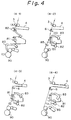
- the first yarn sucking means 82 is swung to return the sucking aperture to the waiting position (B), whereby the first yarn is transferred to the yarn piecing portion of the splicer 81 (shown in Fig. 4-2).
- the second yarn sucking means 83 is rotated and the aperture thereof is moved to a position (C) for sucking the second yarn above the yarn package 90 while the roller driving means 84 is actuated, whereby the arm 84a is rotated enabling the roller 84b to be contacted to the drive roller 71 of the yarn winding means 7.
- the yarn package 90 is rotated in an opposite direction to the yarn winding direction with the driving roller 71.
- the second yarn sucking means 83 When the yarn is withdrawn from the yarn package 90 as a second yarn, the second yarn sucking means 83 is rotated to move back the yarn sucking aperture to a waiting position (D), whereby the second yarn is transferred to the yarn piecing means of the splicer 81 (shown in Fig. 4-2).
- the controller determines that a spun yarn is normally spun from the yarn forming means 2 whereby the splicer is actuated to piece the first and the second yarns to each other (shown in Fig. 4-3).
- the controller determines that a spun yarn is not spun from the yarn forming means 2 due to an abnormal condition in which, for example, the fibers are clogged in the nozzle or the like, therefore a spun yarn could not be sucked by the first yarn sucking means.
- a yarn cutter provided on the splicer 81 or the like is actuated to cut a yarn between the yarn package 90 and the second yarn sucking means 83.
- the controller determines that a thickness of the fiber bundle, i.e., the sliver, is different from a predetermined value or variation in a yarn thickness exists, then immediately stops rotation of the back-roller 11 of the drafting means 1 and simultaneously activates a yarn cutter provided on the splicer 81 to cut a yarn between the yarn package 90 and the second yarn sucking means 83 so as to prevent the normal yarn wound on the yarn package from being pieced with the abnormal spun yarn having a thickness being different from a predetermined value.
- the roller driving means 84 is reversely rotated to rotate the yarn package 90 in an opposite direction.
- the roller driving means 84 is actuated to make an arm 84a swing, whereby the yarn package 90 is removed from a surface of the roller 84b.
- a clutch means of the yarn winding means 7 is actuated, whereby a driving roller 71 is connected to a line shaft causing the start of a yarn winding operation (shown in Fig. 4-4).
- the controller determines that the yarn splicer 81 failed to piece the yarns in the yarn piecing operation and makes the yarn splicer repeat the yarn piecing operation.
- the yarn piecing operation of the present invention can be applied to another spun yarn spinning method in which a plurality of spun yarns spun from separate yarn forming means, for example, two or three, are plied and wound simultaneously on a yarn package as a plied yarn.
- the plied yarn formed by plying a plurality of the spun yarns thus spun is guided to the yarn sensor and the sensor determines whether the plied yarn exists or not or whether an abnormal yarn thickness in the plied yarn exists or not.
- a yarn withdrawn from a yarn package is guided to the second yarn sensor 85, which sensor 85 determines whether a yarn exists or not or whether an abnormal yarn thickness in the yarn exists or not.
- the controller determines that a spun yarn or all of spun yarns thus withdrawn from a yarn package are not sucked by the second yarn sucking means 83.
- the rollers are prevented from being broken due to the fibers being wrapped around a surface of the rollers. Further, one can prevent only one spun yarn being pieced plied yarn.
- the plied spun yarn spinning machine as explained above can be applied to a method in which a plied yarn comprising more than two spun yarns is spun.
- the problem of a yarn having an abnormal thickness being mixed in a yarn package can be prevented and the rollers or apron belts can be prevented from being broken due to fibers wrapped around a surface of the driving rollers in the drafting means.
- different number of yarns for example, only one spun yarn in the first yarns or the second yarns and two spun yarns in the second yarns or the first yarns, are prevented from being pieced to each other as a plied yarn.
- defective yarn knotted portions in a yarn package can be avoided.
- a detector which detects whether the yarn piecing operation succeeds or not is provided separately from the sensor which detects whether the yarn defects exists or not and thereby the yarn piecing operation can be repeatedly carried out immediately when the yarn piecing operation by the yarn piecing means fails, whereby a rate of success in the yarn piecing operation can be improved and an amount of operational work for an operator can be reduced.
- the rollers or apron belts are prevented from being broken due to fibers being wrapped around a surface of the driving rollers in the drafting means.
Landscapes
- Engineering & Computer Science (AREA)
- Mechanical Engineering (AREA)
- Textile Engineering (AREA)
- Spinning Or Twisting Of Yarns (AREA)
Priority Applications (1)
| Application Number | Priority Date | Filing Date | Title |
|---|---|---|---|
| DE1990626261 DE69026261T2 (de) | 1990-11-08 | 1990-11-08 | Verfahren zum Beheben eines Fadenbruches an einer Spinnmaschine |
Applications Claiming Priority (1)
| Application Number | Priority Date | Filing Date | Title |
|---|---|---|---|
| JP1209183A JPH07107212B2 (ja) | 1989-08-10 | 1989-08-10 | 紡績機械の糸継方法 |
Publications (2)
| Publication Number | Publication Date |
|---|---|
| EP0484601A1 true EP0484601A1 (de) | 1992-05-13 |
| EP0484601B1 EP0484601B1 (de) | 1996-03-27 |
Family
ID=16568717
Family Applications (1)
| Application Number | Title | Priority Date | Filing Date |
|---|---|---|---|
| EP90312239A Expired - Lifetime EP0484601B1 (de) | 1989-08-10 | 1990-11-08 | Verfahren zum Beheben eines Fadenbruches an einer Spinnmaschine |
Country Status (3)
| Country | Link |
|---|---|
| US (1) | US5142856A (de) |
| EP (1) | EP0484601B1 (de) |
| JP (1) | JPH07107212B2 (de) |
Cited By (3)
| Publication number | Priority date | Publication date | Assignee | Title |
|---|---|---|---|---|
| EP0717001A1 (de) * | 1994-12-15 | 1996-06-19 | SAVIO MACCHINE TESSILI S.r.l. | Verfahren und Vorrichtung zur Durchführung eines flexibelen und modulierenden Wickelzyklus |
| EP1801271A4 (de) * | 2004-09-16 | 2009-04-01 | Murata Machinery Ltd | Kerngarnspinnmaschine, verfahren zur feststellung der an- oder abwesenheit des kerns bei kerngarn sowie verfahren zum bedienen einer kerngarnspinnmaschine |
| US7770373B2 (en) | 2005-05-16 | 2010-08-10 | Murata Kikai Kabushiki Kaisha | Core fiber detecting method and device in core yarn spinning |
Families Citing this family (10)
| Publication number | Priority date | Publication date | Assignee | Title |
|---|---|---|---|---|
| US5531063A (en) * | 1989-06-15 | 1996-07-02 | The United States Of America As Represented By The Secretary Of The Department Of Agriculture | Device for forming core/wrap yarn |
| DE4027210A1 (de) * | 1990-08-29 | 1992-03-05 | Fritz Stahlecker | Spinnmaschine mit einer vielzahl von spinnstellen und mit einer vorrichtung zum beheben eines fadenbruches |
| US5322228A (en) * | 1991-05-20 | 1994-06-21 | Sumitomo Electric Industries, Inc. | Method for screening optical fiber and apparatus for carrying out method |
| CA2472865C (en) * | 2004-06-29 | 2015-11-17 | Instrumar Limited | Fibre monitoring apparatus and method |
| US7983785B2 (en) | 2004-06-30 | 2011-07-19 | Instrumar Limited | Fibre monitoring apparatus and method |
| DE102005022187A1 (de) * | 2005-05-13 | 2006-11-16 | Saurer Gmbh & Co. Kg | Anspinnverfahren an einer Luftspinnmaschine sowie Spinnvorrichtung und Luftspinnmaschine |
| DE102011082310A1 (de) | 2011-09-07 | 2013-03-07 | Fraunhofer-Gesellschaft zur Förderung der angewandten Forschung e.V. | Vorrichtung, Verfahren und elektroakustisches System zur Nachhallzeitverlängerung |
| CZ306695B6 (cs) * | 2015-11-16 | 2017-05-10 | Rieter Cz S.R.O. | Způsob obnovení předení na tryskovém dopřádacím stroji |
| CZ306694B6 (cs) * | 2015-11-16 | 2017-05-10 | Rieter Cz S.R.O. | Způsob přípravy pracovního místa pro obnovení předení na tryskovém dopřádacím stroji a tryskový dopřádací stroj k jeho provádění |
| JP6538993B1 (ja) * | 2017-11-30 | 2019-07-03 | Spiber株式会社 | 糸管理装置、糸管理方法、及びプログラム |
Citations (3)
| Publication number | Priority date | Publication date | Assignee | Title |
|---|---|---|---|---|
| DE2152295A1 (de) * | 1970-10-20 | 1972-04-27 | Shimadzu Corp | Elektronische Fadenueberwachungs- und Saeuberungsvorrichtung |
| EP0387009A2 (de) * | 1989-03-07 | 1990-09-12 | Toray Engineering Co., Ltd. | Verfahren und Vorrichtung zum Wiederverbinden von Fäden |
| DE3911505A1 (de) * | 1989-04-08 | 1990-10-18 | Schlafhorst & Co W | Verfahren und spulstelle zum herstellen einer fehlerfreien kreuzspule |
Family Cites Families (15)
| Publication number | Priority date | Publication date | Assignee | Title |
|---|---|---|---|---|
| US1425084A (en) * | 1920-06-01 | 1922-08-08 | Phoenix Knitting Works | Twisting and winding machine |
| US3759026A (en) * | 1971-03-24 | 1973-09-18 | W Hope | Yarn breaker and switch for spinning frames |
| EP0016940B1 (de) * | 1979-03-27 | 1983-05-18 | Maschinenfabrik Rieter Ag | Wanderndes Überwachungsgerät für die sukzessive Überwachung der Arbeitsbedingungen an jeder Spinnstelle einer Ringspinnmaschine |
| FR2463211A2 (fr) * | 1979-08-10 | 1981-02-20 | Alsacienne Constr Meca | Systeme de rattache de fil et de nettoyage pour machine de filature |
| DE3022149A1 (de) * | 1980-06-13 | 1981-12-24 | Stahlecker, Fritz, 7347 Bad Überkingen | Umwindegarn-spinnaggregat |
| DE3028453A1 (de) * | 1980-07-26 | 1982-03-18 | Zinser Textilmaschinen Gmbh, 7333 Ebersbach | Spinnmaschine |
| JPS6013941B2 (ja) * | 1980-12-13 | 1985-04-10 | 村田機械株式会社 | 糸捲機における異常糸継防止方法 |
| JPS5930922A (ja) * | 1982-08-12 | 1984-02-18 | Toyoda Autom Loom Works Ltd | オ−プンエンド精紡機における糸継方法 |
| US4650822A (en) * | 1985-02-22 | 1987-03-17 | Union Camp Corporation | Adhesive compositions |
| DE3515765A1 (de) * | 1985-05-02 | 1986-11-06 | W. Schlafhorst & Co, 4050 Mönchengladbach | Offenend-rotor-spinnmaschine |
| DE3524073A1 (de) * | 1985-07-05 | 1987-01-08 | Zinser Textilmaschinen Gmbh | Verfahren und anlage zum beheben von fadenbruechen |
| IT1198038B (it) * | 1985-10-18 | 1988-12-21 | Zinser Textilmaschinen Gmbh | Filatoio |
| JPH0322215Y2 (de) * | 1986-04-24 | 1991-05-15 | ||
| DE3726720A1 (de) * | 1987-08-11 | 1989-02-23 | Zinser Textilmaschinen Gmbh | Verfahren und vorrichtung zum selbsttaetigen fadenansetzen an einer ringspinnmaschine |
| JPH01156519A (ja) * | 1987-12-14 | 1989-06-20 | Murata Mach Ltd | 紡績方法及び紡績装置 |
-
1989
- 1989-08-10 JP JP1209183A patent/JPH07107212B2/ja not_active Expired - Lifetime
-
1990
- 1990-11-08 EP EP90312239A patent/EP0484601B1/de not_active Expired - Lifetime
- 1990-11-08 US US07/610,683 patent/US5142856A/en not_active Expired - Fee Related
Patent Citations (3)
| Publication number | Priority date | Publication date | Assignee | Title |
|---|---|---|---|---|
| DE2152295A1 (de) * | 1970-10-20 | 1972-04-27 | Shimadzu Corp | Elektronische Fadenueberwachungs- und Saeuberungsvorrichtung |
| EP0387009A2 (de) * | 1989-03-07 | 1990-09-12 | Toray Engineering Co., Ltd. | Verfahren und Vorrichtung zum Wiederverbinden von Fäden |
| DE3911505A1 (de) * | 1989-04-08 | 1990-10-18 | Schlafhorst & Co W | Verfahren und spulstelle zum herstellen einer fehlerfreien kreuzspule |
Cited By (5)
| Publication number | Priority date | Publication date | Assignee | Title |
|---|---|---|---|---|
| EP0717001A1 (de) * | 1994-12-15 | 1996-06-19 | SAVIO MACCHINE TESSILI S.r.l. | Verfahren und Vorrichtung zur Durchführung eines flexibelen und modulierenden Wickelzyklus |
| EP1801271A4 (de) * | 2004-09-16 | 2009-04-01 | Murata Machinery Ltd | Kerngarnspinnmaschine, verfahren zur feststellung der an- oder abwesenheit des kerns bei kerngarn sowie verfahren zum bedienen einer kerngarnspinnmaschine |
| CN101018900B (zh) * | 2004-09-16 | 2012-01-11 | 村田机械株式会社 | 包芯纱纺纱机、包芯纱的芯线有无判断方法及包芯纱纺纱机的服务方法 |
| US7770373B2 (en) | 2005-05-16 | 2010-08-10 | Murata Kikai Kabushiki Kaisha | Core fiber detecting method and device in core yarn spinning |
| CN101175878B (zh) * | 2005-05-16 | 2011-07-27 | 村田机械株式会社 | 包芯纱纺纱中的芯线检测方法及装置 |
Also Published As
| Publication number | Publication date |
|---|---|
| EP0484601B1 (de) | 1996-03-27 |
| US5142856A (en) | 1992-09-01 |
| JPH0376835A (ja) | 1991-04-02 |
| JPH07107212B2 (ja) | 1995-11-15 |
Similar Documents
| Publication | Publication Date | Title |
|---|---|---|
| US5862660A (en) | Method for removing yarn defects at a winding head of a bobbin winding machine | |
| EP0484601B1 (de) | Verfahren zum Beheben eines Fadenbruches an einer Spinnmaschine | |
| EP3025995B1 (de) | Garnwicklungsmaschine | |
| EP3524556A1 (de) | Luftspinnmaschine und luftspinnverfahren | |
| US4944145A (en) | Spinning machine for producing feeding packages for twisting | |
| US6637695B2 (en) | Method of winding a traveling yarn at a work station of a spinning bobbin winding machine or of a bobbin winding machine | |
| US4995229A (en) | Process and an arrangement for picking up a yarn end of a spool package during a piecing operation | |
| CN105253703B (zh) | 纱线卷取机以及纱线卷取方法 | |
| US5163279A (en) | Arrangement for producing feeding packages for a twisting operation | |
| JP4489991B2 (ja) | 綾巻ボビンを巻成する繊維機械の運転法 | |
| JPH06322622A (ja) | 自動ワインダ | |
| JP4529977B2 (ja) | コアヤーン紡績機 | |
| US5005348A (en) | Process and an arrangement for producing packages | |
| JP7553257B2 (ja) | 繊維機械の作業ユニットにおいて糸継ぎ結合部を形成するための方法ならびに繊維機械の作業ユニット | |
| JP3218496B2 (ja) | 自動ワインダーの玉揚げ方法 | |
| JP2734805B2 (ja) | 弾性糸を芯糸とするコアヤーン紡績装置における糸継台車の運転方法 | |
| US5272862A (en) | Spinning machine with a yarn piecing mobile servicing carriage having a temporary yarn storage capacity | |
| JP2023142771A (ja) | 糸巻取機及び糸巻取方法 | |
| US5175982A (en) | Process and an arrangement for feeding slivers to a spinning unit | |
| EP0387009A2 (de) | Verfahren und Vorrichtung zum Wiederverbinden von Fäden | |
| JPH01229825A (ja) | チーズ製造方法及び装置 | |
| US5255502A (en) | Yarn piece method and yarn piecing apparatus | |
| JP2734804B2 (ja) | 弾性糸を芯糸とするコアヤーン紡績装置における糸継台車の運転方法 | |
| US5279104A (en) | Process and device for the piecing of an open-end spinning device | |
| JP2004332141A (ja) | 玉揚げ装置を備えた紡績機 |
Legal Events
| Date | Code | Title | Description |
|---|---|---|---|
| PUAI | Public reference made under article 153(3) epc to a published international application that has entered the european phase |
Free format text: ORIGINAL CODE: 0009012 |
|
| AK | Designated contracting states |
Kind code of ref document: A1 Designated state(s): CH DE GB IT LI |
|
| 17P | Request for examination filed |
Effective date: 19921016 |
|
| 17Q | First examination report despatched |
Effective date: 19940520 |
|
| GRAA | (expected) grant |
Free format text: ORIGINAL CODE: 0009210 |
|
| AK | Designated contracting states |
Kind code of ref document: B1 Designated state(s): CH DE GB IT LI |
|
| RAP1 | Party data changed (applicant data changed or rights of an application transferred) |
Owner name: TORAY ENGINEERING CO., LTD. |
|
| REG | Reference to a national code |
Ref country code: CH Ref legal event code: NV Representative=s name: E. BLUM & CO. PATENTANWAELTE |
|
| REF | Corresponds to: |
Ref document number: 69026261 Country of ref document: DE Date of ref document: 19960502 |
|
| ITF | It: translation for a ep patent filed | ||
| PLBE | No opposition filed within time limit |
Free format text: ORIGINAL CODE: 0009261 |
|
| STAA | Information on the status of an ep patent application or granted ep patent |
Free format text: STATUS: NO OPPOSITION FILED WITHIN TIME LIMIT |
|
| 26N | No opposition filed | ||
| PGFP | Annual fee paid to national office [announced via postgrant information from national office to epo] |
Ref country code: GB Payment date: 19981113 Year of fee payment: 9 |
|
| PGFP | Annual fee paid to national office [announced via postgrant information from national office to epo] |
Ref country code: CH Payment date: 19991022 Year of fee payment: 10 |
|
| PG25 | Lapsed in a contracting state [announced via postgrant information from national office to epo] |
Ref country code: GB Free format text: LAPSE BECAUSE OF NON-PAYMENT OF DUE FEES Effective date: 19991108 |
|
| PGFP | Annual fee paid to national office [announced via postgrant information from national office to epo] |
Ref country code: DE Payment date: 19991208 Year of fee payment: 10 |
|
| GBPC | Gb: european patent ceased through non-payment of renewal fee |
Effective date: 19991108 |
|
| PG25 | Lapsed in a contracting state [announced via postgrant information from national office to epo] |
Ref country code: LI Free format text: LAPSE BECAUSE OF NON-PAYMENT OF DUE FEES Effective date: 20001130 Ref country code: CH Free format text: LAPSE BECAUSE OF NON-PAYMENT OF DUE FEES Effective date: 20001130 |
|
| REG | Reference to a national code |
Ref country code: CH Ref legal event code: PL |
|
| PG25 | Lapsed in a contracting state [announced via postgrant information from national office to epo] |
Ref country code: DE Free format text: LAPSE BECAUSE OF NON-PAYMENT OF DUE FEES Effective date: 20010801 |
|
| PG25 | Lapsed in a contracting state [announced via postgrant information from national office to epo] |
Ref country code: IT Free format text: LAPSE BECAUSE OF NON-PAYMENT OF DUE FEES;WARNING: LAPSES OF ITALIAN PATENTS WITH EFFECTIVE DATE BEFORE 2007 MAY HAVE OCCURRED AT ANY TIME BEFORE 2007. THE CORRECT EFFECTIVE DATE MAY BE DIFFERENT FROM THE ONE RECORDED. Effective date: 20051108 |