EP0484674B1 - Procédé pour l'usinage automatique des bords de plaques de verre et appareil pour exécuter le procédé - Google Patents
Procédé pour l'usinage automatique des bords de plaques de verre et appareil pour exécuter le procédé Download PDFInfo
- Publication number
- EP0484674B1 EP0484674B1 EP91116847A EP91116847A EP0484674B1 EP 0484674 B1 EP0484674 B1 EP 0484674B1 EP 91116847 A EP91116847 A EP 91116847A EP 91116847 A EP91116847 A EP 91116847A EP 0484674 B1 EP0484674 B1 EP 0484674B1
- Authority
- EP
- European Patent Office
- Prior art keywords
- plate
- edge
- probe
- movement
- grinder
- Prior art date
- Legal status (The legal status is an assumption and is not a legal conclusion. Google has not performed a legal analysis and makes no representation as to the accuracy of the status listed.)
- Expired - Lifetime
Links
Images


Classifications
-
- B—PERFORMING OPERATIONS; TRANSPORTING
- B25—HAND TOOLS; PORTABLE POWER-DRIVEN TOOLS; MANIPULATORS
- B25J—MANIPULATORS; CHAMBERS PROVIDED WITH MANIPULATION DEVICES
- B25J9/00—Program-controlled manipulators
- B25J9/02—Program-controlled manipulators characterised by movement of the arms, e.g. cartesian coordinate type
-
- B—PERFORMING OPERATIONS; TRANSPORTING
- B24—GRINDING; POLISHING
- B24B—MACHINES, DEVICES, OR PROCESSES FOR GRINDING OR POLISHING; DRESSING OR CONDITIONING OF ABRADING SURFACES; FEEDING OF GRINDING, POLISHING, OR LAPPING AGENTS
- B24B9/00—Machines or devices designed for grinding edges or bevels on work or for removing burrs; Accessories therefor
- B24B9/02—Machines or devices designed for grinding edges or bevels on work or for removing burrs; Accessories therefor characterised by a special design with respect to properties of materials specific to articles to be ground
- B24B9/06—Machines or devices designed for grinding edges or bevels on work or for removing burrs; Accessories therefor characterised by a special design with respect to properties of materials specific to articles to be ground of non-metallic inorganic material, e.g. stone, ceramics, porcelain
- B24B9/08—Machines or devices designed for grinding edges or bevels on work or for removing burrs; Accessories therefor characterised by a special design with respect to properties of materials specific to articles to be ground of non-metallic inorganic material, e.g. stone, ceramics, porcelain of glass
- B24B9/10—Machines or devices designed for grinding edges or bevels on work or for removing burrs; Accessories therefor characterised by a special design with respect to properties of materials specific to articles to be ground of non-metallic inorganic material, e.g. stone, ceramics, porcelain of glass of plate glass
-
- G—PHYSICS
- G05—CONTROLLING; REGULATING
- G05B—CONTROL OR REGULATING SYSTEMS IN GENERAL; FUNCTIONAL ELEMENTS OF SUCH SYSTEMS; MONITORING OR TESTING ARRANGEMENTS FOR SUCH SYSTEMS OR ELEMENTS
- G05B19/00—Program-control systems
- G05B19/02—Program-control systems electric
- G05B19/42—Recording and playback systems, i.e. in which the program is recorded from a cycle of operations, e.g. the cycle of operations being manually controlled, after which this record is played back on the same machine
- G05B19/4202—Recording and playback systems, i.e. in which the program is recorded from a cycle of operations, e.g. the cycle of operations being manually controlled, after which this record is played back on the same machine preparation of the program medium using a drawing, a model
- G05B19/4207—Recording and playback systems, i.e. in which the program is recorded from a cycle of operations, e.g. the cycle of operations being manually controlled, after which this record is played back on the same machine preparation of the program medium using a drawing, a model in which a model is traced or scanned and corresponding data recorded
Definitions
- the present invention relates to a process for the automatic machining of edges of glass plates and to an apparatus for carrying out said process.
- edges of glass plates are usually subjected to a process known as "polished-edge machining", which consists in performing in succession various passes with increasingly finer grinders along the edge of the plate while keeping the abrasion region wet with water; said grinders operate with their axis orthogonal to the plane of the plate to be machined.
- polished-edge machining consists in performing in succession various passes with increasingly finer grinders along the edge of the plate while keeping the abrasion region wet with water; said grinders operate with their axis orthogonal to the plane of the plate to be machined.
- the polished edge machining is currently performed with semiautomatic processes, using apparatuses constituted by a central support with a sucker-fitted table, on which the plate to be machined is fixed, and by a grinder supporting arm which can be turned all around the plate and along which a grinder supporting head can be moved radially; the operator grips the head with his hands and, while keeping it pressed against the plate, moves it tangentially all around said plate, in order to machine its edge; these apparatuses are sometimes equipped with electronic devices and, by using a template, allow to semiautomatically machine parts having a simple contour.
- This method is generally time consuming and requires expert operators who can optimally measure the pressing effort against the edge of the plate so as to avoid damaging it and also avoid removing excess material; besides, if it is necessary to produce a series of identical parts, said parts will usually be slightly different from one another according to the skill of the operator.
- a working centre which is programmable for performing automated operations and which has two working heads, each activated by a plurality of stepping motors, having three degrees of freedom, and being controlled by an electronic unit and by a minicomputer.
- a program unit stores the working centre program and position data defining the path of the working head and process data defining the operations to be performed by the working head at predetermined points along the path of the working head.
- EP-A3-0,092,021 relates to a drillhole centerline determining device comprising an interposer having a central pocket enabling a robot to probe the interposer to learn the location and orientation of the desired drillhole.
- EP-A1-0,377,755 relates to a visually controlled robot system having a robot control device for controlling an operation of a robot body, and a vision sensor system for detecting visual information.
- a common operator panel is also provided which has means for selecting either a first mode for carrying out an operation related to the robot control device, or a second mode for carrying out an operation related to the vision sensor system.
- EP-A3-0,155,218 Also known from EP-A3-0,155,218 is a process as defined in the precharacterising of claim 1. Also known from EP-A3-0,155,218 is an apparatus as defined in the precharacterizing part of claim 3.
- the technical aim of the present invention is to obviate the above described disadvantages, i.e. to provide an automatic apparatus which performs polished-edge machining on glass plates having any contour, without requiring expert operators and ensuring that, in case of batch machinings, all the finished plates are identical.
- this aim is achieved by a process for the automatic machining of an edge of a glass plate as defined in claim 1.
- the above-mentioned aim is achieved by an apparatus for the automatic machining of an edge of a glass plate as defined in claim 3.
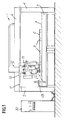
- the reference numeral 1 generally indicates the apparatus for carrying out the polished edge machining according to the invention.
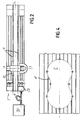
- the apparatus 1 is intended to follow the contour of a glass plate 2 which has the shape of a figure-of-eight in the example illustrated in figure 4.
- a contour comprising straight portions and curved portions with a blended contour, in that the tangents of the curved portions are blended to the straight portions, can be executed on the plate 2.
- the apparatus 1 comprises a frame which extends longitudinally in a direction X-X and has a horizontal table 3 and a sort of longitudinal portal which extends upward like a bridge along the table and above it.
- Said portal has vertical uprights 4, 5 and a horizontal cross-member 6.
- a horizontal surface 7 is fixed onto the table 3 and is intended to receive the glass 2 so that it rests thereon and is arranged horizontally on appropriate supports 8 which can be arranged so as to allow the machining of the contour of the plate: said supports are of the type constituted by suckers associated with a suction unit, and retracting pneumatic abutments are also provided, constituted by cylinder type elements with a vertical axis, which are slidingly connected to the table and are actuated in an extraction direction to center the plate to be machined and are then actuated into a retracted position during the plate machining steps.
- the apparatus 1 furthermore comprises a tool supporting head 9 which is supported by the frame in a manner described hereinafter.
- a carriage 10 is mounted along the cross-member 6 of the frame so that it can slide along appropriate guides 11 connected to the cross-member 6.
- Said carriage 10 can be moved in the direction X-X under the action of per se conventional actuation means 12, constituted for example by a direct-current motor which actuates a ball bearing nut rigidly associated with the carriage.
- a truck 13 is mounted below the carriage 12 and can slide with respect to the carriage along appropriate guides 14 which extend in a direction Y-Y which is orthogonal to the direction X-X.
- Said truck 13 can move in the direction Y-Y under the action of per se conventional actuation means, for example a direct-current motor.
- a slider 20 is mounted on the truck 13 and can slide along vertical guides 21 in the direction Z-Z.
- Said slider 20 can move in the direction Z-Z under the action of actuation means which comprise a direct-current electric motor 22 which is mounted on a platform 23 associated with the truck 13, the shaft whereof rotates, by means of a toothed-belt transmission, a vertical screw 24 the thread whereof engages a ball bearing nut 25 which is rigidly associated with the slider.
- actuation means which comprise a direct-current electric motor 22 which is mounted on a platform 23 associated with the truck 13, the shaft whereof rotates, by means of a toothed-belt transmission, a vertical screw 24 the thread whereof engages a ball bearing nut 25 which is rigidly associated with the slider.
- the tool supporting head 9 is fixed to the slider 20 and comprises a grinder support mandrel 26 which can accommodate diamondized polishing grinders or a probe head for self-learning, as described hereinafter.
- the mandrel 26 is actuated so as to rotate as required by an electric motor 27 which is mounted on the slider 20.
- the grinders are chosen so that they are suitable for performing, in succession, the roughing, finishing and polishing operations.
- the apparatus is furthermore provided with means for sprinkling water at the grinding area, such means being of a generally known type.
- a magazine 28 for the automatic changing of the tools and the loading of the probe is provided on a short side of the apparatus; in the particular case, there is a magazine for five tools plus a self-learning probe 29, but the number of tools might be different.
- the tools are locked in the seat of the mandrel by means of known devices, advantageously by means of spiral springs which act on a double-action linear pneumatic actuation device in which the pressurized air is used to release the tool.
- the self-learning probe 29 is advantageously of the type suitable for detecting the three dimensions X, Y and Z and for transmitting the coordinates with infrared-ray pulses; said probe allows to detect the position of the part and thus to define the placement of the tool at the optimum grinding level, and also allows the sensing, placement and machining of any geometrical contour.
- the infrared-ray transmission of the pulses avoids the presence of transmission cables which would hinder movements.
- the detection of the level Z occurs by lowering the probe onto the plate; by means of this lowering, the level of the upper surface of the plate is detected, and the thickness of the plate is determined by subtracting the level at which the suckers act.
- the apparatus according to the invention furthermore comprises a per se conventional numeric control device 30 which can be supplied with the coordinates of the contour of the plate 2: this can be performed either by means of manual programming from the keyboard, for simple contours, or by self-learning, for more complex contours, by means of successive detections of the coordinates of the edge of the plate on the part of the probe.
- a per se conventional numeric control device 30 which can be supplied with the coordinates of the contour of the plate 2: this can be performed either by means of manual programming from the keyboard, for simple contours, or by self-learning, for more complex contours, by means of successive detections of the coordinates of the edge of the plate on the part of the probe.
- the numeric control device is connected by means of cables to the means for actuating the carriage 10 and to the means for actuating the truck 13 in order to move the head 9 in the directions X-X and Y-Y with continuous contour processing control.
- the numeric control device is also connected to the means which actuate the slider 20 in order to move the head 9 vertically toward and away from the glass to be contoured, as well as to the other motor means for an appropriate control of all the movements of the apparatus and for tool changing in automatic sequence according to the requirements.
- Each of the sequences of self-learning movements is shown in figure 6, and consists of a first large and fast movement I away from the plate L, of a second large and fast movement II in a direction which is orthogonal to the first movement, of a third large and fast movement III for approximate approach to the part until abutment therewith occurs, of a fourth small and rapid backoff movement IV, of a fifth slow movement V for precise approach to the part, and of a sixth small and slow movement VI, at the end of which the pulses related to the sensed coordinates X and Y are transmitted to the computer.
- the straight contour portions extend preferably along the axes X or Y, and in this manner the machining of these portions is performed by moving the grinder only along the direction of the axis X or only along the direction of the axis Y, whereas for the execution of the curved portions or also of the straight inclined portions the grinder is actuated with simultaneous X and Y movements such as to reproduce the required shape.
- the contour of the plate is followed in succession with increasingly finer grinders, indeed in order to perform first roughing, then finishing and finally polishing.
- the grinder is arranged halfway along the thickness of the glass plate, and the glass plate is equally touched by the probe halfway along its thickness in order to sense its contour.
- the polishing grinders are subject to rapid wear, i.e. to rapid variations of their diameter and therefore of their machining contour: the apparatus automatically compensates this wear by moving the grinder axis toward the part being machined according to the power absorbed by the electric motor 27; when a decrease in absorbed power is detected, indicating that the grinder presses less against the plate since it has a smaller diameter, the path of the grinder axis is moved closer to the plate contour: the rpm rate of the motor is simultaneously changed in order to keep the set cutting speed constant.
- the main advantage of the apparatus according to the invention resides in the fact that it allows to machine contours on glass plates in a fully automatic manner, with a single positioning of the plate to be machined.
- the apparatus according to the invention allows to machine complex contours with variable curvatures along said contour also by virtue of the self-learning device, with a reduction in the downtimes for apparatus setup.
Landscapes
- Engineering & Computer Science (AREA)
- Mechanical Engineering (AREA)
- Robotics (AREA)
- Chemical & Material Sciences (AREA)
- Ceramic Engineering (AREA)
- Inorganic Chemistry (AREA)
- Physics & Mathematics (AREA)
- General Physics & Mathematics (AREA)
- Automation & Control Theory (AREA)
- Grinding And Polishing Of Tertiary Curved Surfaces And Surfaces With Complex Shapes (AREA)
- Finish Polishing, Edge Sharpening, And Grinding By Specific Grinding Devices (AREA)
- Polishing Bodies And Polishing Tools (AREA)
Claims (4)
- Procédé pour l'usinage automatique du bord d'une plaque de verre, qui comprend les étapes consistant à :- fixer la plaque de verre (2) sur une table de travail (3),- mémoriser un ensemble de coordonnées spatiales suivant deux axes orthogonaux X et Y du bord de la plaque (2) à usiner,- utiliser un dispositif (30) de commande numérique pour traiter lesdites coordonnées au moyen dudit dispositif (30) de commande numérique afin de déterminer le trajet à suivre par le contour d'un outil de polissage pour produire un contour qui est constitué par des arcs et des lignes droites tangentes à celui-ci,- calculer les déplacements successifs suivant les axes X et Y que doit effectuer le centre de l'outil de polissage afin d'usiner le bord de la plaque (2) en fonction d'au moins un paramètre choisi parmi:a) le diamètre de l'outil de polissage utilisé, etb) l'usure de l'outil de polissage utilisé,- commander, au moyen desdites valeurs calculées, les déplacements le long du bord de la plaque (2) d'une tête d'usinage (9) qui supporte l'outil de polissage,caractérisé en ce qu'il comprend les étapes consistant à :- détecter lesdites coordonnées en effectuant des séquences successives de déplacements auto-adaptatifs le long du bord de la plaque (2) d'une sonde (29) à infra-rouges de transmission des coordonnées,- actionner ladite tête (9) de manière à retirer les uns après les autres d'un magasin d'outil (24):sachant que la séquence des déplacements auto-adaptatifs comprend un déplacement ample et rapide dans une première direction (I) qui s'éloigne de la plaque (2), un déplacement ample et rapide dans une seconde direction (II) orthogonale à la première direction (I) de déplacement, un déplacement ample et rapide dans une troisième direction (III) d'approche approximative de la plaque (2) jusqu'à ce qu'il se produise un contact, un petit mouvement rapide de recul dans une quatrième direction (IV) qui s'éloigne de la plaque (2), un déplacement lent dans une cinquième direction (V) d'approche précise de la plaque (2) et un déplacement faible et lent dans une sixième direction (VI) opposée à ladite cinquième direction (V) de déplacement, etc) ladite sonde auto-adaptative (29), etd) des outils de polissage diamantés progressivement plus fins pour produire de ce fait, au moyen de passes successives, un bord poli sur le bord de la plaque (2),
sachant que le contact avec la plaque (2) pendant le déplacement dans ladite seconde direction (II) ou le défaut de contact pendant les déplacements indique une modification de la direction de la plaque (2) par rapport aux séquences précédentes, les directions et les orientations de déplacement étant dans ce cas tournées de 90 degrés. - Procédé selon la revendication 1, comprenant en outre les étapes consistant à :- transmettre des coordonnées détectées par ladite sonde pendant le déplacement dans lesdites première, seconde, troisième, quatrième, cinquième et sixième directions (I, II, III, IV, V, VI) par l'intermédiaire d'impulsions infra-rouges, et- recevoir et traiter lesdites impulsions infra-rouges envoyées par ladite sonde (29) au niveau dudit dispositif (30) de commande numérique.
- Appareil pour l'usinage automatique du bord d'une plaque de verre, qui comprend une table de travail (3) sensiblement horizontale, munie d'un moyen (8) de centrage et de fixation destiné à une plaque de verte (2) au moins, et sur laquelle est fixée une poutre (6), un chariot (10) étant actionné le long de ladite poutre (6) pour se déplacer suivant deux axes X et Y qui correspondent aux directions de la longueur et de la largeur de ladite table (3), une pièce coulissante (20) portant une tête (9) de support d'outil d'usinage, ladite tête comprenant un mandrin (26) de support d'outil de polissage entraîné par un moteur (27) et présentant un axe vertical, ledit appareil comprenant en outre un dispositif (30) de commande numérique destiné à mémoriser des coordonnées du contour du bord de la plaque (2) devant être usinée,
caractérisé en ce que ledit dispositif de commande numérique est conçu pour commander les déplacements de la tête (9) de support d'outil afin de détecter le contour à l'aide d'une sonde (29), ledit chariot (10) porte des guides verticaux (21) sur lesquels ladite pièce coulissante (20) est montée et est actionnée pour se déplacer suivant l'axe vertical Z, un magasin d'outils (24) étant prévu pour une pluralité d'outils de polissage et pour une sonde (29), ledit dispositif de commande numérique actionne la tête (9) pour qu'elle retire successivement dudit magasin d'outils (24) ladite sonde auto-adaptative (29) et des outils de polissage diamantés de plus en plus fins, un moyen de transmission des coordonnées détectées à l'aide d'impulsions infrarouges étant couplé à ladite sonde (29) et un moyen de réception des impulsions infra-rouges envoyées par ladite sonde (29) étant couplé audit dispositif (30) de commande numérique. - Appareil d'usinage du bord selon la revendication 3, comprenant en outre un moyen pour compenser automatiquement l'usure de ladite pluralité d'outils de polissage destinés aux opérations de dégrossissage, finition et polissage, incluant un moyen pour détecter la puissance absorbée par ledit moteur (27) qui entraîne ledit mandrin (26) de support d'outil de polissage et un moyen pour augmenter la vitesse dudit moteur (27) en cas d'usure de ladite pluralité d'outils de polissage, maintenant de ce fait une vitesse de coupe constante.
Applications Claiming Priority (2)
| Application Number | Priority Date | Filing Date | Title |
|---|---|---|---|
| IT00367790A IT1242582B (it) | 1990-10-05 | 1990-10-05 | Procedimento per la lavorazione in automatico a filo lucido del bordo di lastre di vetro di forma qualsiasi e macchina per la esecuzione di tale procedimento. |
| IT367790 | 1990-10-05 |
Publications (3)
| Publication Number | Publication Date |
|---|---|
| EP0484674A2 EP0484674A2 (fr) | 1992-05-13 |
| EP0484674A3 EP0484674A3 (en) | 1992-08-05 |
| EP0484674B1 true EP0484674B1 (fr) | 1995-04-19 |
Family
ID=11111339
Family Applications (1)
| Application Number | Title | Priority Date | Filing Date |
|---|---|---|---|
| EP91116847A Expired - Lifetime EP0484674B1 (fr) | 1990-10-05 | 1991-10-02 | Procédé pour l'usinage automatique des bords de plaques de verre et appareil pour exécuter le procédé |
Country Status (5)
| Country | Link |
|---|---|
| US (1) | US5216844A (fr) |
| EP (1) | EP0484674B1 (fr) |
| DE (1) | DE69109055T2 (fr) |
| ES (1) | ES2073086T3 (fr) |
| IT (1) | IT1242582B (fr) |
Cited By (1)
| Publication number | Priority date | Publication date | Assignee | Title |
|---|---|---|---|---|
| EP2039464A1 (fr) | 2007-09-21 | 2009-03-25 | FOR.EL. BASE di VIANELLO FORTUNATO & C. S.n.c. | Machine automatique et procédé automatique pour meuler le bord périmétrique de feuilles de verre |
Families Citing this family (17)
| Publication number | Priority date | Publication date | Assignee | Title |
|---|---|---|---|---|
| FR2680477B1 (fr) * | 1991-08-22 | 1995-12-08 | Pont A Mousson | Procede et machine d'ebarbage. |
| EP0771612B1 (fr) * | 1991-08-27 | 2002-03-06 | Mitsubishi Jukogyo Kabushiki Kaisha | Appareil à jet de surface de sol |
| IT1262263B (it) * | 1993-12-30 | 1996-06-19 | Delle Vedove Levigatrici Spa | Procedimento di levigatura per profili curvi e sagomati e macchina levigatrice che realizza tale procedimento |
| JPH08267347A (ja) * | 1995-03-31 | 1996-10-15 | Shin Etsu Handotai Co Ltd | オリエンテーション・フラットを有するウエーハ面取り部の鏡面研磨方法とその装置 |
| US5713784A (en) * | 1996-05-17 | 1998-02-03 | Mark A. Miller | Apparatus for grinding edges of a glass sheet |
| IT1303231B1 (it) | 1998-08-14 | 2000-11-02 | Bottero Spa | Tavolo da taglio per la lavorazione di lastre di vetro. |
| EP1195227A3 (fr) * | 2000-10-03 | 2002-07-17 | Karsten Kristiansen | Procédé et dispositif pour le meulage des bords de produits plats empilés verticalement |
| US6629877B2 (en) * | 2001-02-21 | 2003-10-07 | Leon A. Cerniway | Precision glass grinding |
| US6722959B2 (en) * | 2002-03-22 | 2004-04-20 | Glassline Corporation | Combination 2-plane CNC positioning grinder with CNC positioning drill |
| US6769964B2 (en) | 2002-08-02 | 2004-08-03 | Saint-Cobain Abrasives Technology Company | Abrasive tool having a unitary arbor |
| WO2009147465A1 (fr) * | 2008-06-05 | 2009-12-10 | Cemex Research Group Ag | Coproduction d’électricité améliorée lors de la fabrication de clinker de ciment |
| CN102114607B (zh) * | 2010-12-07 | 2012-09-05 | 富阳德迈机械有限公司 | 一种玻璃磨边的方法 |
| CN103302558B (zh) * | 2013-06-05 | 2016-01-20 | 江苏高博智融科技有限公司 | 一种数控复合磨床及其磨削方法 |
| RU2619651C2 (ru) * | 2015-10-05 | 2017-05-17 | Общество с ограниченной ответственностью "Спецмаш" | Станок для обработки кромок плоских изделий |
| RU187637U1 (ru) * | 2018-04-13 | 2019-03-14 | федеральное государственное бюджетное образовательное учреждение высшего образования "Иркутский национальный исследовательский технический университет" (ФГБОУ ВО "ИРНИТУ") | Установка для обработки кромок на длинномерных деталях типа профилей |
| CN110788600B (zh) * | 2019-11-04 | 2021-08-13 | 东风汽车有限公司 | 一种抓取装置以及采用其的压装设备 |
| CN110695836A (zh) * | 2019-11-26 | 2020-01-17 | 李金� | 一种滑动轴承套抛光设备 |
Family Cites Families (12)
| Publication number | Priority date | Publication date | Assignee | Title |
|---|---|---|---|---|
| IT1047161B (it) * | 1975-09-03 | 1980-09-10 | Olivetti & Co Spa | Centro di lavorazione per automazione programmabile con dispositivo tattile autoadattivo |
| GB1556443A (en) * | 1977-05-20 | 1979-11-21 | Nat Res & Dev Corp | Liquid level monitoring |
| FR2476057A2 (fr) * | 1979-09-21 | 1981-08-21 | Rhone Poulenc Ind | Perfectionnement au procede de recuperation globale de l'uranium, des terres rares, du thorium et de l'yttrium contenus dans une solution acide |
| BR8300266A (pt) * | 1982-01-20 | 1983-10-25 | Saint Gobain Vitrage | Processo para o comando automatico do caminho de contorno sobretudo de uma maquina de esmerilhamento periferico de arestas para chapas de vidro e instalacoes para a realizacao do processo |
| US4485453A (en) * | 1982-03-29 | 1984-11-27 | International Business Machines Corporation | Device and method for determining the location and orientation of a drillhole |
| EP0092091B2 (fr) * | 1982-04-15 | 1991-01-30 | Allied Corporation | Appareil pour la fabrication de poudre magnétique |
| DE3301170C2 (de) * | 1983-01-15 | 1985-02-14 | Vereinigte Glaswerke Gmbh, 5100 Aachen | Programmgesteuerte Kantenschleifmaschine für Glasscheiben |
| AU3583084A (en) * | 1983-12-10 | 1985-06-13 | Aida Engineering Ltd. | Playback grinding robot |
| EP0155218B1 (fr) * | 1984-03-14 | 1990-02-07 | Saint-Gobain Vitrage International | Traceuse à servo-commande impulsionnelle,notamment pour le travail des volumes de verres |
| DD222814A1 (de) * | 1984-04-13 | 1985-05-29 | Schiffbau Veb K | Schweissroboter zum schweissen horizontaler kehlnaehte in mehrseitigen fachkonstruktionen |
| DE3532903A1 (de) * | 1985-09-14 | 1987-03-26 | Waldrich Werkzeugmasch | Portalschleifmaschine mit schleifscheiben-wechselvorrichtung |
| JP2548027B2 (ja) * | 1988-06-30 | 1996-10-30 | ファナック株式会社 | アークビジョンセンサ操作方式 |
-
1990
- 1990-10-05 IT IT00367790A patent/IT1242582B/it active IP Right Grant
-
1991
- 1991-10-02 EP EP91116847A patent/EP0484674B1/fr not_active Expired - Lifetime
- 1991-10-02 DE DE69109055T patent/DE69109055T2/de not_active Expired - Fee Related
- 1991-10-02 ES ES91116847T patent/ES2073086T3/es not_active Expired - Lifetime
- 1991-10-02 US US07/769,700 patent/US5216844A/en not_active Expired - Fee Related
Non-Patent Citations (1)
| Title |
|---|
| Shimon:"Handbook of Industrial Robotics", John Wiley & Sons 1985, page 361 * |
Cited By (1)
| Publication number | Priority date | Publication date | Assignee | Title |
|---|---|---|---|---|
| EP2039464A1 (fr) | 2007-09-21 | 2009-03-25 | FOR.EL. BASE di VIANELLO FORTUNATO & C. S.n.c. | Machine automatique et procédé automatique pour meuler le bord périmétrique de feuilles de verre |
Also Published As
| Publication number | Publication date |
|---|---|
| ES2073086T3 (es) | 1995-08-01 |
| DE69109055D1 (de) | 1995-05-24 |
| IT9003677A1 (it) | 1992-04-05 |
| IT1242582B (it) | 1994-05-16 |
| EP0484674A2 (fr) | 1992-05-13 |
| DE69109055T2 (de) | 1995-08-31 |
| EP0484674A3 (en) | 1992-08-05 |
| US5216844A (en) | 1993-06-08 |
| IT9003677A0 (it) | 1990-10-05 |
Similar Documents
| Publication | Publication Date | Title |
|---|---|---|
| EP0484674B1 (fr) | Procédé pour l'usinage automatique des bords de plaques de verre et appareil pour exécuter le procédé | |
| EP0562232B1 (fr) | Machine outil | |
| JPS59169720A (ja) | 電気加工用マシニングセンタ | |
| US6585564B1 (en) | Machine tool device and its working fluid feed device | |
| EP0489856A1 (fr) | Methode et appareil pour tailler une lentille optique | |
| EP1175962B1 (fr) | Dispositif de production de verres optiques | |
| CA2276724A1 (fr) | Machine-outil et methode d'usinage | |
| US7172495B2 (en) | Method and apparatus using a sensor for finish-machining teeth | |
| CN112757066A (zh) | 一种成型无心外圆磨床 | |
| US7785173B2 (en) | Superfinishing machine and method | |
| CN215035972U (zh) | 一种成型无心外圆磨床 | |
| US5038012A (en) | Electrical discharge process and machining apparatus | |
| CN110936245B (zh) | 一种盘式刹车片内外弧边缘倒角磨床 | |
| CN217890321U (zh) | 一种数控机床加工自动化生产线 | |
| KR100932540B1 (ko) | 다면을 가공하는 복합 가공기 | |
| CN218136777U (zh) | 刀具刀刃的磨削装置 | |
| CN111390578B (zh) | 一种五轴联动数控机床 | |
| JP4712586B2 (ja) | Nc工作機械 | |
| EP0406775A2 (fr) | Rectifieuse | |
| CN215279920U (zh) | 一种版辊外圆粗精加工一体机 | |
| CN113042765A (zh) | 一种版辊外圆粗精加工一体机 | |
| CN113334154A (zh) | 一种用于精密成型刀片连续加工的复合机床及其加工工艺 | |
| CN220051134U (zh) | 一种磨头耗材自动更换的抛光系统 | |
| CN219882140U (zh) | 一种五轴数控研磨设备 | |
| CN119794822B (zh) | 一种多轴复合加工机床 |
Legal Events
| Date | Code | Title | Description |
|---|---|---|---|
| PUAI | Public reference made under article 153(3) epc to a published international application that has entered the european phase |
Free format text: ORIGINAL CODE: 0009012 |
|
| AK | Designated contracting states |
Kind code of ref document: A2 Designated state(s): DE ES FR GB |
|
| PUAL | Search report despatched |
Free format text: ORIGINAL CODE: 0009013 |
|
| AK | Designated contracting states |
Kind code of ref document: A3 Designated state(s): DE ES FR GB |
|
| 17P | Request for examination filed |
Effective date: 19920923 |
|
| 17Q | First examination report despatched |
Effective date: 19930823 |
|
| GRAA | (expected) grant |
Free format text: ORIGINAL CODE: 0009210 |
|
| AK | Designated contracting states |
Kind code of ref document: B1 Designated state(s): DE ES FR GB |
|
| ET | Fr: translation filed | ||
| REF | Corresponds to: |
Ref document number: 69109055 Country of ref document: DE Date of ref document: 19950524 |
|
| REG | Reference to a national code |
Ref country code: ES Ref legal event code: FG2A Ref document number: 2073086 Country of ref document: ES Kind code of ref document: T3 |
|
| PLBE | No opposition filed within time limit |
Free format text: ORIGINAL CODE: 0009261 |
|
| STAA | Information on the status of an ep patent application or granted ep patent |
Free format text: STATUS: NO OPPOSITION FILED WITHIN TIME LIMIT |
|
| 26N | No opposition filed | ||
| PGFP | Annual fee paid to national office [announced via postgrant information from national office to epo] |
Ref country code: GB Payment date: 19961017 Year of fee payment: 6 |
|
| PGFP | Annual fee paid to national office [announced via postgrant information from national office to epo] |
Ref country code: ES Payment date: 19961025 Year of fee payment: 6 |
|
| PGFP | Annual fee paid to national office [announced via postgrant information from national office to epo] |
Ref country code: FR Payment date: 19961029 Year of fee payment: 6 |
|
| PGFP | Annual fee paid to national office [announced via postgrant information from national office to epo] |
Ref country code: DE Payment date: 19961128 Year of fee payment: 6 |
|
| PG25 | Lapsed in a contracting state [announced via postgrant information from national office to epo] |
Ref country code: GB Free format text: LAPSE BECAUSE OF NON-PAYMENT OF DUE FEES Effective date: 19971002 |
|
| PG25 | Lapsed in a contracting state [announced via postgrant information from national office to epo] |
Ref country code: ES Free format text: LAPSE BECAUSE OF NON-PAYMENT OF DUE FEES Effective date: 19971003 |
|
| PG25 | Lapsed in a contracting state [announced via postgrant information from national office to epo] |
Ref country code: FR Free format text: THE PATENT HAS BEEN ANNULLED BY A DECISION OF A NATIONAL AUTHORITY Effective date: 19971031 |
|
| GBPC | Gb: european patent ceased through non-payment of renewal fee |
Effective date: 19971002 |
|
| PG25 | Lapsed in a contracting state [announced via postgrant information from national office to epo] |
Ref country code: DE Free format text: LAPSE BECAUSE OF NON-PAYMENT OF DUE FEES Effective date: 19980701 |
|
| REG | Reference to a national code |
Ref country code: FR Ref legal event code: ST |
|
| REG | Reference to a national code |
Ref country code: ES Ref legal event code: FD2A Effective date: 19981113 |